EP0406199A2 - Anordnung zur Ausführung des Beschiessens eines Ziels mittels eines Schnellfeuerartilleriegeschütztes - Google Patents
Anordnung zur Ausführung des Beschiessens eines Ziels mittels eines Schnellfeuerartilleriegeschütztes Download PDFInfo
- Publication number
- EP0406199A2 EP0406199A2 EP90850244A EP90850244A EP0406199A2 EP 0406199 A2 EP0406199 A2 EP 0406199A2 EP 90850244 A EP90850244 A EP 90850244A EP 90850244 A EP90850244 A EP 90850244A EP 0406199 A2 EP0406199 A2 EP 0406199A2
- Authority
- EP
- European Patent Office
- Prior art keywords
- target
- adjustment
- shelling
- piece
- ordnance piece
- Prior art date
- Legal status (The legal status is an assumption and is not a legal conclusion. Google has not performed a legal analysis and makes no representation as to the accuracy of the status listed.)
- Withdrawn
Links
Images
Classifications
-
- F—MECHANICAL ENGINEERING; LIGHTING; HEATING; WEAPONS; BLASTING
- F41—WEAPONS
- F41G—WEAPON SIGHTS; AIMING
- F41G3/00—Aiming or laying means
- F41G3/04—Aiming or laying means for dispersing fire from a battery ; for controlling spread of shots; for coordinating fire from spaced weapons
Definitions
- the present invention relates to an arrangement for carrying out shelling of a target by means of a rapid-firing ordnance piece, for example cannon, howitzer or launcher for artillery missiles, with a number of ammunition units which can be fired successively one after the other.
- the arrangement comprises manoeuvring/computer equipment which, as a function of input data, generates information for controlling of the ordnance piece and/or adjustment or fixing of one or more factors relating to flight parameter(s) of the respective ammunition unit.
- the said factors can consist of or concern the launch speed or charge size, air resistance (coefficient) or brake function, etc.
- the ordnance pieces can in this respect be of the type comprising elevatable and sideways-directable barrels. It is also known to provide control information to such ordnance pieces by means of computer-based equipment, to which various data, for example firing distance, launch speeds, wind information etc can be introduced for giving control information corresponding to the desired and calculated parameters and firing conditions.
- the invention proposes a solution to this problem, inter alia, and the feature which can be principally regarded as characterizing the invention is that the controlling of the ordnance piece and/or the ammunition units is coordinated and in that the information output from the manoeuvring equipment constitutes adjustment or selection information which allocates to the ammunition units different flight times between the ordnance piece and the target, so that they reach the target at essentially the same point in time after the launch from the ordnance piece.
- the adjustment or selection information received from the manoeuvring/computer equipment is preferably used for varying the angle of elevation of the ordnance piece, and in conjunction with this the adjustment or selection information can also affect or fix the various air resistance (coefficients) of the ammunition units.
- the adjustment or selection information received from the equipment results in a variation simultaneous in the angle of elevation of the cannon and in the launch speeds of the shells.
- a further exemplary embodiment is that the said extracted information is used for altering the angle of elevation and the points in time for the start of extra braking of the shells or the like.
- the launching speed of the ammunition units is the same, while the ordnance piece can be controlled within a predetermined range of elevation.
- the total firing time for the shelling of the target is comparatively long, and the information received from the equipment affects or fixes the trigger times for brake members on the ammunition units, which trigger times are in this case chosen to be different.
- the said launch speeds can vary, for example, between 1000 m/s and 960 m/s in accordance with a predetermined pattern, which affords the desired simultaneity of impact on the target.
- this information preferably produces a continuous or step-wise dumping of the barrel of the ordnance piece from the highest to the lowest angle of elevation.
- the invention it is possible, with one and the same weapon, to achieve simultaneity in the impact of the shells or the like on a target.
- the shells which are launched first are caught up by the following shells before they reach the impact site.
- the invention can also be used in sideways-directable ordnance pieces where it is possible to combine simultaneity with desired strike patterns, i.e. the invention can also be used on target patterns which have a relatively large spread purely in terms of area.
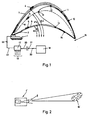
- a caterpillar-tracked ordnance piece of known type is shown by 1.
- the ordnance piece has a large-bore barrel 2, for example 15.5 cm, which can be actuated in a known manner to different angles of elevation, of which some have been indicated by ⁇ 1- ⁇ 4.
- the ordnance piece is rapid-firing and can fire for example 6-10 shots/min.
- the ordnance piece is also assumed to have magazines which permit long shooting rounds per total shooting times, for example rounds of up to 15 shots and shooting times of 35-60 sec.
- shells for example 4, 5 and 6, are to be fired at different angles of elevation and follow different trajectories, for example trajectories 7, 8 and 9.
- the launch speed is the same for the various shells.
- the shells are to be provided in a known manner with extra brake members (for example fold-out flaps or push-away tip hoods) which can be activated by fuses of known type.
- the fuses are activated in turn in connection with the launching of the respective shell from the barrel.
- the fuses are adjustable to different trigger times, after which the brake members are activated, calculated from the launching from the firing weapon.
- points 10-15 on the various ballistic trajectories indicate the positions where the brake members of the shell are to be activated in order for the shells in the case shown to strike essentially simultaneously one and the same target site 16.
- the adjustment or fixing of the parameters of the shells can be determined using computer-based manoeuvring equipment 17 which is included in or is connected to the ordnance piece 1.
- the equipment 17 can be connected to firing-control equipment 18.
- Data 19 relating to the present or coming shots is input to the equipment 17.
- the data can relate to the target distance, firing intervals, weather conditions, etc.
- Firing commands 20 can also be input to the equipment from the firing-control equipment 18. This input can be effected via a wireless or fixed connection 21.
- the manoeuvring equipment is designed in a known manner to process such incoming data 19 and firing commands 20.
- the manoeuvring equipment outputs at its output 22 control information 23 to the barrel-controlling member/or shell-advancing member and/or shell-actuating member and/or shell function-selecting member etc. of the ordnance piece 1.
- the control information 23 is used as adjustment or selection information which allocates or indicates the different parameters for the members listed above which afford the desired simultaneity of impact of the shells on the target.
- One or more parameters, for example the firing interval can be built into the function of the caterpillar-tracked ordnance piece. In the case with elevation variation, the firing preferably begins at the highest elevation, after which the barrel is dumped continuously or stepwise during the continued firing. Such a function can also be built into the ordnance piece and does not need to be controlled per se, but instead, for example, only selected among other possible elevation or dumping cases.
- Figure 2 shows that a used caterpillar-tracked ordnance piece 1′ is designed with a sideways-directable function, in which respect the total sideways-directable angle has been indicated by ⁇ .
- a characteristic feature of the firing case according to Figure 2 is again the simultaneity of the impact of the shells.
Landscapes
- Engineering & Computer Science (AREA)
- General Engineering & Computer Science (AREA)
- Aiming, Guidance, Guns With A Light Source, Armor, Camouflage, And Targets (AREA)
- Medicinal Preparation (AREA)
- Measurement Of The Respiration, Hearing Ability, Form, And Blood Characteristics Of Living Organisms (AREA)
- Electromechanical Clocks (AREA)
- Stroboscope Apparatuses (AREA)
- Management, Administration, Business Operations System, And Electronic Commerce (AREA)
Applications Claiming Priority (2)
| Application Number | Priority Date | Filing Date | Title |
|---|---|---|---|
| SE8902329 | 1989-06-28 | ||
| SE8902329A SE463990B (sv) | 1989-06-28 | 1989-06-28 | Anordning foer att medelst snabbskjutande pjaes effektuera beskjutning av ett maal |
Publications (2)
| Publication Number | Publication Date |
|---|---|
| EP0406199A2 true EP0406199A2 (de) | 1991-01-02 |
| EP0406199A3 EP0406199A3 (en) | 1992-11-25 |
Family
ID=20376413
Family Applications (1)
| Application Number | Title | Priority Date | Filing Date |
|---|---|---|---|
| EP19900850244 Withdrawn EP0406199A3 (en) | 1989-06-28 | 1990-06-20 | Arrangement for carrying out shelling of a target by means of a rapid-firing ordnance piece |
Country Status (6)
| Country | Link |
|---|---|
| US (1) | US5121672A (de) |
| EP (1) | EP0406199A3 (de) |
| CA (1) | CA2020004A1 (de) |
| FI (1) | FI97490C (de) |
| NO (1) | NO170040C (de) |
| SE (1) | SE463990B (de) |
Cited By (1)
| Publication number | Priority date | Publication date | Assignee | Title |
|---|---|---|---|---|
| US5218161A (en) * | 1991-05-06 | 1993-06-08 | Hughes Aircraft Company | Projectile wall barrage system |
Families Citing this family (3)
| Publication number | Priority date | Publication date | Assignee | Title |
|---|---|---|---|---|
| SE508352C2 (sv) * | 1991-09-16 | 1998-09-28 | Bofors Ab | Ammunitionsenhet samt sätt för framställning av sådan |
| GB0223437D0 (en) * | 2002-10-03 | 2003-02-26 | Alenia Marconi Systems Ltd | Improvements in or relating to targeting systems |
| SE2200029A1 (sv) * | 2022-03-15 | 2023-09-16 | Bae Systems Bofors Ab | Metod för samordnad brisad av projektiler |
Family Cites Families (7)
| Publication number | Priority date | Publication date | Assignee | Title |
|---|---|---|---|---|
| ZA72674B (en) * | 1971-02-17 | 1972-10-25 | Thomson Csf | System for aiming projectiles at close range |
| SE445952B (sv) * | 1983-03-25 | 1986-07-28 | Bofors Ab | Anordning for att minska projektilspridning |
| SE458151B (sv) * | 1984-09-04 | 1989-02-27 | Bofors Ab | Saett att optimera maaltaeckningen foer ett automatkanonluftvaern |
| CH667523A5 (en) * | 1985-07-31 | 1988-10-14 | Oerlikon Buehrle Ag | Strike rate improvement appts. for weapon against airborne target - uses selective braking of fired shells with controlled detonation at optimum strike point at surface of imaginary sphere |
| SE8600380L (sv) * | 1986-01-29 | 1987-07-30 | Bofors Ab | Anordning for att minska projektilspridning |
| US4718187A (en) * | 1986-10-02 | 1988-01-12 | Electronic Warfare Associates, Inc. | Trigger means for a weapon control system |
| SE462181B (sv) * | 1987-10-22 | 1990-05-14 | Bofors Ab | Saett att oeka traeffsannolikheten foer automatkanonluftvaern |
-
1989
- 1989-06-28 SE SE8902329A patent/SE463990B/sv not_active IP Right Cessation
-
1990
- 1990-06-20 EP EP19900850244 patent/EP0406199A3/en not_active Withdrawn
- 1990-06-27 FI FI903247A patent/FI97490C/fi active IP Right Grant
- 1990-06-27 NO NO902868A patent/NO170040C/no not_active IP Right Cessation
- 1990-06-27 CA CA002020004A patent/CA2020004A1/en not_active Abandoned
- 1990-06-28 US US07/544,873 patent/US5121672A/en not_active Expired - Lifetime
Cited By (1)
| Publication number | Priority date | Publication date | Assignee | Title |
|---|---|---|---|---|
| US5218161A (en) * | 1991-05-06 | 1993-06-08 | Hughes Aircraft Company | Projectile wall barrage system |
Also Published As
| Publication number | Publication date |
|---|---|
| FI97490B (fi) | 1996-09-13 |
| SE8902329L (sv) | 1990-12-29 |
| FI97490C (fi) | 1996-12-27 |
| SE463990B (sv) | 1991-02-18 |
| EP0406199A3 (en) | 1992-11-25 |
| NO902868L (no) | 1991-01-02 |
| NO170040C (no) | 1992-09-02 |
| SE8902329D0 (sv) | 1989-06-28 |
| US5121672A (en) | 1992-06-16 |
| FI903247A0 (fi) | 1990-06-27 |
| NO170040B (no) | 1992-05-25 |
| NO902868D0 (no) | 1990-06-27 |
| CA2020004A1 (en) | 1990-12-29 |
Similar Documents
| Publication | Publication Date | Title |
|---|---|---|
| RU2275585C2 (ru) | Способ управления направлением полета ракеты и ракета | |
| US4664034A (en) | Fettered shot | |
| US4858532A (en) | Submunitions | |
| JPH09506961A (ja) | 銃身アセンブリ | |
| EP0138942B1 (de) | Vorrichtung zum vermindern der geschossstreuung bei einem waffensystem | |
| DE3507758C2 (de) | Handfeuerwaffe und Schrotmunition hierfür | |
| WO2011012250A1 (de) | Waffe, insbesondere reichweitengesteuerte druckluftwaffe | |
| US4498394A (en) | Arrangement for a terminally guided projectile provided with a target seeking arrangement and path correction arrangement | |
| Farjo et al. | Ballistics and mechanisms of tissue wounding | |
| DE102022002227A1 (de) | Projektil-Waffe mit gesteuerter Projektil-Reichweitel | |
| AU681876B2 (en) | A barrel assembly | |
| JPH05312497A (ja) | 特別に形成された砲弾の所期の分解による成功確率の向上方法 | |
| JP2003532589A (ja) | 攻撃用航空機 | |
| EP0406199A2 (de) | Anordnung zur Ausführung des Beschiessens eines Ziels mittels eines Schnellfeuerartilleriegeschütztes | |
| US7044045B2 (en) | Method for programming the shattering of projectiles and tube weapon with programming system | |
| US6616093B1 (en) | Method and device for correcting the trajectory of a spin-stabilised projectile | |
| EP0313536A1 (de) | Verfahren zur Verbesserung der Trefferwahrscheinlichkeit von automatischen Luftabwehrwaffen | |
| CN1175241C (zh) | 小型武器 | |
| CN202013148U (zh) | 一种120mm反坦克火箭训练弹 | |
| RU2669242C1 (ru) | Устройство для повышения скорости метания снарядов или пуль | |
| RU2836924C1 (ru) | Оружие против атакующих дронов (варианты) | |
| RU2853698C1 (ru) | Снаряд-накидка для поражения цели | |
| RU2836926C1 (ru) | Способ применения БПЛА и система осуществления способа | |
| US5218161A (en) | Projectile wall barrage system | |
| IL153619A (en) | High kinetic energy projectile with a plurality of subcalibre segments |
Legal Events
| Date | Code | Title | Description |
|---|---|---|---|
| PUAI | Public reference made under article 153(3) epc to a published international application that has entered the european phase |
Free format text: ORIGINAL CODE: 0009012 |
|
| AK | Designated contracting states |
Kind code of ref document: A2 Designated state(s): AT BE CH DE DK ES FR GB GR IT LI NL SE |
|
| PUAL | Search report despatched |
Free format text: ORIGINAL CODE: 0009013 |
|
| AK | Designated contracting states |
Kind code of ref document: A3 Designated state(s): AT BE CH DE DK ES FR GB GR IT LI NL SE |
|
| 17P | Request for examination filed |
Effective date: 19930330 |
|
| 17Q | First examination report despatched |
Effective date: 19940802 |
|
| STAA | Information on the status of an ep patent application or granted ep patent |
Free format text: STATUS: THE APPLICATION IS DEEMED TO BE WITHDRAWN |
|
| 18D | Application deemed to be withdrawn |
Effective date: 19970402 |