EP0406407B1 - Schnellinfusionsvorrichtung - Google Patents
Schnellinfusionsvorrichtung Download PDFInfo
- Publication number
- EP0406407B1 EP0406407B1 EP90902866A EP90902866A EP0406407B1 EP 0406407 B1 EP0406407 B1 EP 0406407B1 EP 90902866 A EP90902866 A EP 90902866A EP 90902866 A EP90902866 A EP 90902866A EP 0406407 B1 EP0406407 B1 EP 0406407B1
- Authority
- EP
- European Patent Office
- Prior art keywords
- volume
- reservoir
- filter
- rapid infusion
- patient
- Prior art date
- Legal status (The legal status is an assumption and is not a legal conclusion. Google has not performed a legal analysis and makes no representation as to the accuracy of the status listed.)
- Expired - Lifetime
Links
- 238000001802 infusion Methods 0.000 title claims abstract description 43
- 230000037361 pathway Effects 0.000 claims abstract description 18
- 239000012530 fluid Substances 0.000 claims abstract description 10
- 238000005086 pumping Methods 0.000 claims abstract description 7
- 239000007788 liquid Substances 0.000 claims abstract description 4
- 210000004369 blood Anatomy 0.000 claims description 19
- 239000008280 blood Substances 0.000 claims description 19
- 238000010926 purge Methods 0.000 claims description 18
- 239000000463 material Substances 0.000 claims description 15
- 238000001914 filtration Methods 0.000 claims description 10
- 239000004677 Nylon Substances 0.000 claims description 5
- 229920001778 nylon Polymers 0.000 claims description 5
- 239000004033 plastic Substances 0.000 claims description 4
- 230000009471 action Effects 0.000 claims description 3
- 230000002441 reversible effect Effects 0.000 claims description 3
- 230000003247 decreasing effect Effects 0.000 claims description 2
- 239000012535 impurity Substances 0.000 claims description 2
- 239000002245 particle Substances 0.000 claims description 2
- 239000011248 coating agent Substances 0.000 claims 1
- 238000000576 coating method Methods 0.000 claims 1
- 238000007789 sealing Methods 0.000 claims 1
- 238000010438 heat treatment Methods 0.000 abstract description 26
- 230000001105 regulatory effect Effects 0.000 abstract description 5
- 230000001154 acute effect Effects 0.000 abstract description 2
- 238000004519 manufacturing process Methods 0.000 abstract description 2
- 206010021137 Hypovolaemia Diseases 0.000 abstract 1
- 239000002991 molded plastic Substances 0.000 abstract 1
- 238000000034 method Methods 0.000 description 7
- 230000000694 effects Effects 0.000 description 3
- 238000001356 surgical procedure Methods 0.000 description 3
- 230000008901 benefit Effects 0.000 description 2
- 230000006835 compression Effects 0.000 description 2
- 238000007906 compression Methods 0.000 description 2
- 238000011109 contamination Methods 0.000 description 2
- 230000035939 shock Effects 0.000 description 2
- 238000003860 storage Methods 0.000 description 2
- 229910000838 Al alloy Inorganic materials 0.000 description 1
- 208000023329 Gun shot wound Diseases 0.000 description 1
- 206010028980 Neoplasm Diseases 0.000 description 1
- 206010039203 Road traffic accident Diseases 0.000 description 1
- XAGFODPZIPBFFR-UHFFFAOYSA-N aluminium Chemical compound [Al] XAGFODPZIPBFFR-UHFFFAOYSA-N 0.000 description 1
- 229910052782 aluminium Inorganic materials 0.000 description 1
- 210000000601 blood cell Anatomy 0.000 description 1
- 230000036760 body temperature Effects 0.000 description 1
- 201000011510 cancer Diseases 0.000 description 1
- 230000008859 change Effects 0.000 description 1
- 238000010276 construction Methods 0.000 description 1
- 230000001276 controlling effect Effects 0.000 description 1
- 230000001627 detrimental effect Effects 0.000 description 1
- 230000006872 improvement Effects 0.000 description 1
- 238000001990 intravenous administration Methods 0.000 description 1
- 210000004185 liver Anatomy 0.000 description 1
- 239000011159 matrix material Substances 0.000 description 1
- 230000010412 perfusion Effects 0.000 description 1
- 230000000717 retained effect Effects 0.000 description 1
- 230000003319 supportive effect Effects 0.000 description 1
- 238000013022 venting Methods 0.000 description 1
- 238000010792 warming Methods 0.000 description 1
Images



Classifications
-
- A—HUMAN NECESSITIES
- A61—MEDICAL OR VETERINARY SCIENCE; HYGIENE
- A61M—DEVICES FOR INTRODUCING MEDIA INTO, OR ONTO, THE BODY; DEVICES FOR TRANSDUCING BODY MEDIA OR FOR TAKING MEDIA FROM THE BODY; DEVICES FOR PRODUCING OR ENDING SLEEP OR STUPOR
- A61M5/00—Devices for bringing media into the body in a subcutaneous, intra-vascular or intramuscular way; Accessories therefor, e.g. filling or cleaning devices, arm-rests
- A61M5/44—Devices for bringing media into the body in a subcutaneous, intra-vascular or intramuscular way; Accessories therefor, e.g. filling or cleaning devices, arm-rests having means for cooling or heating the devices or media
-
- A—HUMAN NECESSITIES
- A61—MEDICAL OR VETERINARY SCIENCE; HYGIENE
- A61M—DEVICES FOR INTRODUCING MEDIA INTO, OR ONTO, THE BODY; DEVICES FOR TRANSDUCING BODY MEDIA OR FOR TAKING MEDIA FROM THE BODY; DEVICES FOR PRODUCING OR ENDING SLEEP OR STUPOR
- A61M5/00—Devices for bringing media into the body in a subcutaneous, intra-vascular or intramuscular way; Accessories therefor, e.g. filling or cleaning devices, arm-rests
- A61M5/14—Infusion devices, e.g. infusing by gravity; Blood infusion; Accessories therefor
- A61M5/142—Pressure infusion, e.g. using pumps
-
- A—HUMAN NECESSITIES
- A61—MEDICAL OR VETERINARY SCIENCE; HYGIENE
- A61M—DEVICES FOR INTRODUCING MEDIA INTO, OR ONTO, THE BODY; DEVICES FOR TRANSDUCING BODY MEDIA OR FOR TAKING MEDIA FROM THE BODY; DEVICES FOR PRODUCING OR ENDING SLEEP OR STUPOR
- A61M5/00—Devices for bringing media into the body in a subcutaneous, intra-vascular or intramuscular way; Accessories therefor, e.g. filling or cleaning devices, arm-rests
- A61M5/14—Infusion devices, e.g. infusing by gravity; Blood infusion; Accessories therefor
- A61M5/165—Filtering accessories, e.g. blood filters, filters for infusion liquids
-
- A—HUMAN NECESSITIES
- A61—MEDICAL OR VETERINARY SCIENCE; HYGIENE
- A61M—DEVICES FOR INTRODUCING MEDIA INTO, OR ONTO, THE BODY; DEVICES FOR TRANSDUCING BODY MEDIA OR FOR TAKING MEDIA FROM THE BODY; DEVICES FOR PRODUCING OR ENDING SLEEP OR STUPOR
- A61M5/00—Devices for bringing media into the body in a subcutaneous, intra-vascular or intramuscular way; Accessories therefor, e.g. filling or cleaning devices, arm-rests
- A61M5/14—Infusion devices, e.g. infusing by gravity; Blood infusion; Accessories therefor
- A61M5/168—Means for controlling media flow to the body or for metering media to the body, e.g. drip meters, counters ; Monitoring media flow to the body
- A61M5/16831—Monitoring, detecting, signalling or eliminating infusion flow anomalies
- A61M5/16854—Monitoring, detecting, signalling or eliminating infusion flow anomalies by monitoring line pressure
-
- A—HUMAN NECESSITIES
- A61—MEDICAL OR VETERINARY SCIENCE; HYGIENE
- A61M—DEVICES FOR INTRODUCING MEDIA INTO, OR ONTO, THE BODY; DEVICES FOR TRANSDUCING BODY MEDIA OR FOR TAKING MEDIA FROM THE BODY; DEVICES FOR PRODUCING OR ENDING SLEEP OR STUPOR
- A61M2205/00—General characteristics of the apparatus
- A61M2205/36—General characteristics of the apparatus related to heating or cooling
- A61M2205/3653—General characteristics of the apparatus related to heating or cooling by Joule effect, i.e. electric resistance
Definitions
- This invention relates to a device as defined in the preamble of claim 1 for the rapid infusion of circulatory supportive fluids such as blood into a patient.
- the device comprises both durable or permanent components and disposable sub-components.
- the disposable sub-components include various components which physically come into contact with the fluid being infused.
- the principal advantage achieved from this arrangement resides in the fact that after each use, the disposable components are destroyed and replaced with new sterile components to preclude contamination from patient to patient as well as from medical personnel to patient.
- a common method of rapid infusion includes the use of a plurality of infusion sites simultaneously. Infusion bags or bags of stored banked blood are interconnected by intravenous tubing. Frequently, a plurality of medical personnel are required to oversee the various infusion sites and to personally ensure the flow of blood from the blood bags or monitor the pumps which infuse the blood to the patient.
- FR-A-2 188 392 discloses a device of the kind as defined in the preamble of claim 1 with which micro-wave energy is used for heating the blood to be infused.
- applying of micro-waves to the blood may be detrimental to the blood-cells.
- the rapid infusion device is composed of two systems.
- One system includes durable equipment, i.e., equipment which can be used over and over again, such as the roller pump and its related controls, a permanently mounted heating element and its related controls, and mounting bracket structure for attaching the heating element to the housing of the roller pump.
- the other systems include the disposable components of the RID such as the blood reservoir.
- a disposable length of for example one quarter inch PVC tubing, is also provided to connect the filter-reservoir to the heating unit.
- the disclosed Rapid Infusion Device is a mechanical pumping system for rapidly delivering filtered, bubble-free, warmed blood to a patient suffering from acute hypovolema.
- the principle of operation of the disclosed invention is one of overcoming resistance mechanically.
- the flow of fluids is totally regulated by the resistance encountered at the smallest tubing orifice along the infusion pathway.
- the word volume is used to describe or refer to the fluid delivered by the device as any desired fluid other than blood may also be delivered by the device.
- the RID provides an apparatus for the rapid infusion of volume being pumped. Additionally, the RID provides a means of de-aerating the volume and also a heating means for maintaining the volume at the desired temperature.
- the pump utilized is a variable speed unit so that the amount of volume being pumped in can be increased merely by increasing the rpm of the pumping unit.
- the reservoir contains plural stages of filters and is provided with a plurality of inlets whereby volume from multiple sources can be fed into the reservoir to satisfy any high demand requirements of a patient.
- the RID comprises a permanent system and a disposable system.
- the disposable system includes all the components with which the volume comes into direct contact.
- the disposable aspect of the invention provides an extra measure of protection against contamination to a subsequent patient.
- Another object of the invention is to provide an apparatus having a permanent system and a disposable system.
- a further object of the invention is to provide a RID in which the disposable portion includes all components which come into direct contact with the volume being infused.
- Yet another object of the invention is to provide an apparatus which de-aerates and heats the volume being infused.
- Still another object of the invention is to provide an apparatus which is compact, multi-functional, and capable of operation by a single person.
- a further object of the invention is to provide a RID which includes a multi-filter arrangement for cleansing the volume prior to infusion.
- Another object of the invention is to provide a RID which also includes a pressure control valve for regulating system pressure and, more specifically, infusion pressure to the patient.
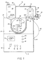
- control panel 12 On the upper right portion of control panel 12 are located AC/DC selector switch 18, stop/forward switch 19 for a motor (not shown) for driving roller pump 22.
- stop/forward switch 19 Above stop/forward switch 19 is located the reverse switch 20 for reversing the rotation of roller pump 22.
- roller pump 22 mounted on top of control panel 12 is pump housing 21 which serves as the mounting support for roller pump 22 and its drive motor (not shown).
- Roller pump 22 comprises a pair of walls 23, 23A forming a raceway, which tubing 29 is inserted into and supported thereby.
- a pair of roller support arms 25 extend from shaft 24, each of which supports a roller 26 at the distal end thereof for engagement with tubing 29.
- Each of the support arms 25 extend in opposite directions with respect to each other from shaft 24.
- heat exchange component 30 mounted on upper surface 27 of pump housing 21 are the various components of the disposable unit including filter/reservoir 28, heat exchange component 30 and associated tubing line 29 leading from filter/reservoir 28 to roller pump 22 which discharges pumped volume to heat exchange component 30 which is in the form of an inverted U-shaped member.
- the upper portion of heat exchange component 30 is interconnected with two-way purge by-pass valve 31 which connects with purge by-pass line 32 back to filter/reservoir 28.
- the right leg of heat exchange component 30 includes an outlet line 33 which connects with the by-pass to patient two-way valve 34.
- the left leg of heat exchange component 30 includes an inlet stem portion 30A for connection with line 29.
- Two-way valve 34 can be set to direct pumped volume to either patient line 35 or purge by-pass line 36 back to filter/reservoir 28.
- Bracket 37 which is shown in dashed lines, serves as the mounting bracket for permanent heating element 38.
- Thermostatic control of permanent heating element 38 is provided by knob 39 for controlling the temperature of the volume.
- Extending from the base of permanent heating element 38 is electrical cord 40 provided with plug 41 which is plugged into control panel 12 and thereby supplies electrical current to permanent heating element 38.
- the device 10 is provided with AC and DC controls in the event that there is a power failure or the device 10 is to be used in an area where AC power is not available.
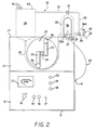
- FIG. 2 provides a complete view of all the disposable components.
- the disposable components illustrated provide pathways for volume in the various operating modes of the system.
- the disposable unit provides access to the system through its three inlet ports 42.
- the volume to be pumped through the system may be pumped, poured, or drained into the filter/reservoir 28 through ports 42.
- Temporary storage, filtration, heating and the direction of volume flow is controlled by the disposable unit.
- System pressure is regulated in the unit by the spirng loaded pressure control valve 45.
- De-aerating of volume is accomplished by removing the cap on air vent 43 to allow the passage of air in and out of the system and the positioning of the purge by-pass two-way valve 31.
- air vent 43 is closed by cap 43A thereover as illustrated in Figs. 4 and 5.
- Flow to the patient and alternative by-pass route for volume is achieved in the unit by setting the by-pass-to-patient two-way valve 34 in the desired position provided for in Figs. 11-14.
- the disposable unit combines the filter/reservoir 28 with its filtration function, heat exchange component 30, two directional control valves 31 and 34 and the system pressure regulating control valve 45 into one unit.
- This unit is disposable as it comes in contact with volume and is considered potentially contaminated and not to be re-used. All parts of the system coming in contact with either volume or patient are disposable, including the PVC connecting line 29 between the filter/reservoir 28 and heater unit 30 and the catheter (not shown) connected to line 35 to the patient for infusing the patient.
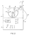
- Fig. 3 the reader can readily see the durable or permanent non-disposable components of RID 10 with the relationship of the permanent components such as heating element 38, its supporting bracket 37 which serves as its mount, and thermostat 39 with its control knob 39A. Additionally, conical recess 27A, which receives and supports the conical lowermost portion 28A of the filter/reservoir 28 when inserted therein, is readily seen. Omitted from Fig. 3 is tubing line 29 which is normally disposed in the raceway formed by walls 23 and 23A since tubing line 29 is removed as with the parts of the disposable unit.
- Fig. 4 there is illustrated a complete showing of the disposable unit 50 of the RID 10 and its relationship to permanent heater element 38.
- the only two disposable items not illustrated here are the piece of PVC tubing 29 which interconnects fitting 28B of filter/reservoir 28 with stem 30A of heater unit 30 and the catheter (not shown) which connects with line 35 to the patient.
- Disposable unit 50 shown in Fig. 4 in operation provides filtration of volume in filter/reservoir 28, acts as a vessel to provide temporary storage volume in the reservoir 28, and provides a controlled pathway for volume to flow, when valves 31 and 34 are set in their desired positions. Heat exchange is also accomplished in disposable unit 50 by way of the relationship of heat exchange component 30 with permanent heating element 38.
- the housing of the disposable unit 50 is made of plastic, molded in two halves, filters, valves and the aluminum-telfa interior wall of the heating unit 30, are installed and the halves are then joined, adhered and sealed for liquid integrity.
- the disposable unit 50 is designed for a single use and is destroyed thereafter. Similarly, all other pathways coming into direct contact with volume are disposed of and/or destroyed, a safety feature to avoid possible contaminaton of the disposable unit 50 and other volume pathways. Other volume pathways include all PVC lines 29 and 35 used in the device.
- permanent heating element 38 is illustrated in Fig. 4 to show its relationship with the disposable unit 50, it is a durable permanent part of RID 10 and is mounted on pump housing 21 via bracket 37.
- FIG. 5 there is illustrated a cross-sectional view taken along the line 5-5 of Fig. 4 showing one of the three inlet ports 42 since the other two inlet ports 42 are hidden by first inlet port 42.
- the inlet port 32A for purge by-pass line 32.
- Baffle 46 is located in the upper left interior corner of filter/reservoir 28 and extends the full width thereof.
- Filter 55 is shown standing vertically in filter/reservoir 28.
- a pair flanges 47 and 48 project upwardly therefrom permitting filter 55 to rest therebetween and retained thereat on the left of conical portion 28A.
- Filter/reservoir 28 provides another safety feature with the added function of storing volume to be infused into the patient.
- the capacity of the vessel is 3000 ml.
- the baffle 46 is molded into the filter/reservoir 28 housing during manufacturing and functions to create a vortex minimizing any effect which flow may have on the volume to be infused.
- the baffle 46 directs the incoming volume into the coarse side of the filter 55.
- the air vent 43 in filter/reservor 28 is operated by loosening screw cap 43A on vent 43 to allow air to enter and leave RID 10.
- By-pass inlet port 32A allows for the return of volume to filter/reservoir 28 when the device is being purged of air, operated in the by-pass mode and when pressure to the patient has become great enough to open the spring pressure control valve 45.
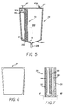
- Fig. 6 shows details of the filter frame 56 per se which has the purpose of holding the Cottonow "3" material 59 which is part of the three layered second stage of filter 55.
- a two stage filtration system including a first stage with a layer of coarse sponge plastic material 57 which is positioned on the fill side of the filter/reservoir 28 and functions to remove material in the volume of over 100 to 150 microns in size.
- the coarse filter material 57 is compressed against the next three layers of filter material in which fine filtration takes place.
- fine filtration functions to remove any remaining impurities in the volume of 27 to 40 microns in size.
- Fine filtration of volume is achieved by passage through three layers of filter material, including a first layer of nylon mesh 58, followed by Cottonow "3" material 59, and a second layer of nylon mesh 58.
- volume is passed into front reservoir chamber 28B for circulation in the system.
- the filter 55 is assembled by inserting Cottonow filter material 59 in the center of the frame 56.
- a fine nylon mesh "sock" 58 fused into two sides is slipped over the frame 56 containing the Cottonow material 59, forming three layers.
- the coarse layer 57 of filter material is then applied to the frame 56 to complete the wafer effect.
- Coarse layer 57 is made of plastic sponge material woven in a matrix to prevent particles in excess of 150 microns from passing through it. After the frame 56 is assembled with filter media, it is installed and sealed in the filter seat formed by seat flanges 47 and 48.
- heat exchange component 30 may be seen with its various connections 30A, 33, and 31A to the various pathways of the system.
- heat exchange component 30 includes a hollow interior to permit the passage of volume therethrough and is shaped in the form of an inverted-U.
- the inverted-U member is made of an aluminum alloy with the inner wall 51 coated with aluminum-telfa to assist in the conduction of heat from heating element 38 to heat exchange component 30 and thence to the volume flowing therethrough.
- the exterior aluminum wall 38A of the heating element 38 and the interior wall 51 of heat exchange component 30 are disposed in a male-female relationship.
- Heat exchange component 30 receives its volume supply from roller pump 22 which has created the flow for the entire system. As volume flows through heat exchange component 30, heat exchange between volume and the walls 38A and 51 takes place and recirculated volume is heated to a pre-set temperature by the setting of thermostat control knob 39A. The heater element 38 is heated by 115 volts, AC current via grounded cord 40 plugged into an accessory outlet on the control panel 12.
- the heat exchange component 30 is considered to be another safety feature, as infusing volume to a patient under 37 degrees C., can cause the patient to go into a state of shock.
- Heating element 38 has an upper arched portion which conforms to U-shaped configuration of heat exchange component 30.
- Thermostat 39 may be seen with control knob 39A for setting the desired temperature in Fig. 9.
- heating element 38 and thermostat 39 are durable components of the RID 10.
- Spring loaded pressure control valve 45 which may be seen in Fig. 10, provides another of the enumerated safety features of the RID 10.
- pressure control valve 45 comprises a threaded screw 60 which is threaded into stationary disc 65.
- a graduated cylindrical housing 66 Extending upwardly above valve 45 is a graduated cylindrical housing 66 with a removable cap 64 thereon to permit access to the screw head 67 which is provided with a slot (not shown) in its upper surface to receive a screwdriver to make the necessary adjustment to the valve 45.
- Attached to the lowermost end of screw 60 is a perforated base disc 61 which biases spring 62 into engagement with ball 63.
- Disc 61 is perforated to permit volume to flow therethrough when ball 63 is unseated from seat 35A.
- valve 45 The function of valve 45 is to regulate system pressure and, more specifically, infusion pressure to the patient.
- valve 45 includes a spring loaded, adjustable ball valve 63 which seats on seat 35A, with helical spring 62 having a known resiliency that can be adjusted with compression. When the screw 60 is advanced, compression on the spring 62 is increased and when withdrawn, decreased.
- the adjustable limits of the valve 45 are limited by the distance the adjusting screw 60 can travel in its housing 66.
- An adjustable range of 100 to 300 mm Hg is provided and access to the adjustment screw 60 is obtained through the access port when cap 64 is removed.
- the normal setting for valve 45 is in the range of 230-300 mm Hg, but may be changed depending on the body size of the patient or any other variable which may indicate that a change in pressure is desirable.
- the pressure control valve 45 is positioned as near as possible to the patient to sense an overpressure condition. When such a condition exists, the valve 45 will open by unseating from seat 35A and volume will escape around the ball 63 through perforations in disc 61 and back through the system in the pathways 36A, 36, and 32.
- the illustrations of the valve 45 are not intended to be “as built” drawings, but rather to indicate its position and general construction characteristics.
- Fig. 11 is the first of four figures depicting the flow of volume in four operating modes of the device.
- the filter/reservoir 28 is filled from a source of volume.
- the volume to be pumped through the system may be supplied to the device from a variety of containers or methods to keep the filter/reservoir 28 at any desired level.
- the objective of the mode of operation illustrated in Fig. 11 is to purge the system of air.
- the filter/reservoir outlet 28B is connected directly to the pump 22, and volume flows from the outlet port 28B through the line 29 fed through the pump.
- the outlet of line 29 from pump 22 is connected directly to inlet port 30A of the heat exchange component 30.
- Flow is developed by the action of roller pump 22 as the rollers 26 impinge on line 29 forcing volume therethrough.
- the two-way by-pass to patient valve 34 is closed to the patient and closed to the purge-by-pass line 36.
- the purge-by-pass two-way valve 31 is opened to the filter/reservoir 28, and open to the air purge position, to allow the evacuation of air via line 32 and reservoir vent 43.
- the duration of this mode of operation is for a period sufficient to make the system air free.
- This mode of operation is a further safety procedure and prevents the infusion of air to the patient.
- Fig. 12 there is shown the flow of volume during the by-pass mode. This mode of operation normally follows the system purge procedure illustrated in Fig. 11 and is also preliminary to the operation of the device, i.e., volume to patient.
- the filter/reservoir 28 is filled from the volume source and flow follows its normal course from the roller pump 22 and into the inlet port 30A of heat exchange component 30.
- Heat exchange component 30 has been set at the desired temperature setting.
- Two-way by-pass to patient valve 34 is closed to the patient and opened to the filter/reservoir 28, and volume is continuously recirculated until the device is ready for use, i.e., until the volume has been heated to the desired temperature.
- This mode is another very desirable safety feature since it raises the temperature of refrigerated or ambient temperature volume to body temperature before it is infused to the patient thereby avoiding a shock effect to the patient which would be caused by sub-body temperature volume.
- FIG. 13 the normal mode of operation of RID 10 may be seen with the path of volume flow to the patient.
- This mode of operation follows the purge procedure and the recirculation procedure for warming volume to the desired temperature.
- the filter/reservoir 28 is filled from the volume source and flows from outlet port 28B of the filter/reservoir 28 through the pump to the inlet port 30A of heat exchange component 30.
- the by-pass-to-patient valve 34 is opened to the patient and closed to the purge by-pass line 36 and pressure control valve 45 is also closed due to bias of spring 62 on ball 63, keeping ball 63 on its seat 35A.
- Fig. 14 there is shown the flow path of volume when there is an increase of back pressure in the volume pathway to the patient.
- spring loaded pressure control valve 45 is normally closed during all modes of operation.
- normal flow to patient is depicted with pressure control valve 45 open.
- This valve is a further safety feature and is positioned in the system to sense an over-pressure condition to the patient.
- pressure control valve 45 When pressure is too great to the patient, i.e., higher than the range set for the valve 45, 230-300 mm Hg, the valve 45 will release back pressure from the patient.
- valve 45 When valve 45 is opened, volume will flow into the purge by-pass line 36A and return to the filter/reservoir 28 for recirculation via lines 36 and 32.
- the spring loaded pressure control valve 45 is a safety device which prevents elevated perfusion pressure to the patient.
- the set-up and assembly of the RID 10 is as follows: Attach heater element 38 to pump housing 21 through the use of mounting bracket 37 which is attached to pump housing 21 by a first pair of bolts and a second pair of bolts for securing heater element 38 to bracket 37.
- the new disposable unit 50 which includes filter/resevoir 28 and heat exchange component 30 with their associated pathways and valves, on top of roller pump aligning the female inverted "U” of heat exchange component 30 with the male inverted “U” of heating element 38. Ensure good surface contact between the walls of these two units. The fit of the units will be sufficient to provide stability for these disposable components when seated in position on roller pump 22.
- the RID 10 is ready for the pre-operating checks which include the following:
- Roller pump 22 is a standard industrial roller pump commonly found in hospital applications of a various nature, but normally those applications which require the movement of liquids at a modulated rate. Any pump of similar capability may be used in conjunction with the disposable components and other disposable parts of the RID.
Landscapes
- Health & Medical Sciences (AREA)
- Vascular Medicine (AREA)
- Engineering & Computer Science (AREA)
- Anesthesiology (AREA)
- Biomedical Technology (AREA)
- Heart & Thoracic Surgery (AREA)
- Hematology (AREA)
- Life Sciences & Earth Sciences (AREA)
- Animal Behavior & Ethology (AREA)
- General Health & Medical Sciences (AREA)
- Public Health (AREA)
- Veterinary Medicine (AREA)
- External Artificial Organs (AREA)
- Infusion, Injection, And Reservoir Apparatuses (AREA)
Claims (18)
- Schnellinfusionsvorrichtung für die Schnellzufuhr eines gefilterten, blasenfreien, erwärmten Volumens zu einem Patienten, mit einer austauschbaren Komponente, die ein Reservoir (28) für das Volumen und sämtliche Unterkomponenten beinhaltet, die mit dem einem Patienten infundierten Volumen in Berührung kommen, einer bleibenden Dauereinheit, die die wiederverwendbaren Komponenten aufweist, einschließlich eines Antriebsmittels, das mit einer Pumpeneinrichtung (22) wirkungsmäßig verbunden ist, einer Heizeinrichtung (38) und ihr zugehöriger Steuerung und einer austauschbaren Länge einer flexiblen Rohrleitung (29), welche als Pumpenkammer der genannten Pumpeneinrichtung (22) dient und Durchgänge (28b, 30a) der genannten austauschbaren Komponente verbindet, welche auch eine Wärmetauschereinheit (30) aufweist, die mit der Heizeinrichtung (38) zusammenwirkt, wodurch ein warmes, gefiltertes, blasenfreies Volumen aus Blut oder einer anderen Flüssigkeit durch eine einzige medizinische Person schnell einem Patienten infundiert werden kann, dadurch gekennzeichnet, daß die genannte austauschbare Komponente eine integrale Einheit (50) aufweist, beinhaltend- das genannte Filter/Reservoir (28) mit darin angeordneter Filtereinrichtung (55);- die genannte Wärmetauschereinheit (30), die mit der genannten Heizeinrichtung (38) zusammenwirkt;- die genannten Durchgänge (28b, 30a) für das Volumen;- eine Ventileinrichtung (31, 34), die der genannten Wärmetauschereinheit (30) und den genannten Durchgängen (28b, 30a) zugehörig ist;- die genannte austauschbare Länge der Rohrleitung, die mit dem genannten Reservoir (28) und der genannten Wärmetauschereinheit (30) an ihren beiden entgegengesetzten Enden verbunden ist;und dadurch, daß das genannte Filter/Reservoir (28), die genannte Wärmetauschereinheit (30), die genannte Ventileinrichtung (31, 34) und die genannen Volumendurchgänge der genannten austauschbaren Einheit (50) zusammen aus zwei Hälften gebildet sind, die nach in Stellung bringen der genannten Filtereinrichtung (55) in dem genannten Reservoir (28) miteinander verbunden und flüssigkeitssicher abgedichtet sind.
- Schnellinfusionsvorrichtung nach Anspruch 1, bei der das genannte Filter/Reservoir (28) eine Mehrzahl Versorgungseinlässe (42), einen Rücklaufeinlaß (32A), einen Auslaß (28B) sowie ein Entlüftungsventil (43) zum Entfernen von Luft aus dem System vor dem Infundieren des gepumpten Volumens in einen Patienten aufweist, wobei das genannte Reservoir (28) außerdem eine Leitflächeneinrichtung (46) beinhaltet, die unterhalb der genannten Mehrzahl der Versorgungseinlässe (42) angeordnet ist, und der genannte Rücklaufeinlaß (32A) und die Filtereinrichtung (55) innerhalb des genannten Reservoirs angeordnet sind.
- Schnellinfusionsvorrichtung nach Anspruch 2, bei der die genannte Leitflächeneinrichtung eine bogenförmige Leitwand (46) aufweist, die das ankommende Volumen in eine horizontale Richtung gegen die genannte Filtereinrichtung (55) hin und durch diese hindurch lenkt, wodurch eine Vewirbelung in der Strömung erzeugt wird, was dazu dient, eine mögliche Beschädigung des Volumens durch Prallwirkung zu verhindern.
- Schnellinfusionsvorrichtung nach Anspruch 2 oder Anspruch 3, bei der die genannte Filtereinrichtung ein Zweistufenfilter aufweist, wobei die erste Stufe (57) dazu dient, Teilchen größer als 150 Mikron aus dem genannten Volumen zu entfernen und die genannte zweite Stufe ein mehrlagiger Sandwichaufbau (56) aus Filtermaterial ist, das jedwede Verunreinigungen von 27-40 Mikron Größe entfernt.
- Schnellinfusionsvorrichtung nach Anspruch 4, bei der die genannte erste Filterstufe (57) ein grobes Schwammaterial aus Kunststoff ist, das an der Füllseite des genannten Reservoirs (28) angeordnet ist.
- Schnellinfusionsvorrichtung nach Anspruch 4 oder Anspruch 5, bei der der genannte, mehrlagige Sandwichaufbau drei Lagen von Filtermaterial aufweist, wobei die erste Lage (58) aus Nylonnetz besteht, gefolgt durch eine Lage (59) aus Cottonow "3"-Material, welche neben einer dritten Lage gelegen ist, die eine weitere Lage aus Nylonnetz ist, wobei beide Stufen der genannten Filtereinrichtung durch einen Filterrahmen (56) innerhalb des genannten Reservoirs (28) getragen sind.
- Schnellinfusionsvorrichtung nach einem der Ansprüche 1 bis 6, bei der sämtliche Unterkomponenten, die mit dem dem Patienten infundierten Volumen in Berührung kommen, einschließlich der austauschbaren Länge der Leitung (26), welche als Pumpenkammer dient, in der vorgefertigten, einheitlichen, austauschbaren Einheit (50) enthalten sind, die durch eine Gehäuseeinrichtung (21) getragen ist, welche auch die genannte Pumpeneinrichtung (22), die genannte Antriebseinrichtung, die genannte Heizeinrichtung (38) und die genannte zugehörige Steuereinrichtung (39) trägt.
- Schnellinfusionsvorrichtung nach Anspruch 7, bei der ein bleibendes, wiederverwendbares Untersystem eine Antriebsmotoreinrichtung und eine zweite Gehäuseeinrichtung (11) aufweist, die die genannte Antriebsmotoreinrichtung (24) einschließt und eine Steuerpulteinrichtung (12) beinhaltet, die genannte erste Gehäuseinrichtung (21) an der Oberseite der genannten zweiten Gehäuseeinrichtung (11) angeordnet ist, die genannte Pumpeneinrichtung (22) und die genannte Heizeinrichtung (38) an der genannten ersten Gehäuseeinrichtung (21) angeordnet sind, wobei die genannte erste Gehäuseeinrichtung (21) als tragende Basis für die genannte vorgefertigte, einheitliche, austauschbare Einheit (50) dient.
- Schnellinfusionsvorrichtung nach Anspruch 7 oder Anspruch 8, bei der das genannte Filter/Reservoir (28) das genannte Entlüftungsventil (43), an seiner obersten Wand angeordnet, beinhaltet, eine quer verlaufende Leitwand (46) unmittelbar unter der genannten Mehrzahl von Einlässen angeordnet ist, das genannte Filter/Reservoir (28) eine konische Bodenwand (28A) mit einem Auslaß (28B) aufweist, der an der untersten Stelle der genannten konischen Bodenwand (28A) gelegen ist, und die genannte konische Wand außerdem ein Paar Leisten (47, 48) beinhaltet, die von der Innenfläche einer Seite der genannten konischen Wand (28A) nach oben vorspringen.
- Schnellinfusionsvorrichtung nach einem der Ansprüche 7 bis 9, bei der die genannte Wärmetauschereinheit (30) ein als umgekehrtes U geformtes Glied (30) aufweist, das einen Einlaß (30A) und ein Paar Auslässe (31A, 33) aufweist, wobei die Außenwand, die die Innenwand (51) des genannten U-förmigen Gliedes (30) bildet, mit einer Beschichtung aus Aluminium-Telfa versehen ist, um die Wärmeübergangsrate zu verbessern, wenn sie in Anlage an die äußere Wand (38A) der genannten Heizeinrichtung (38) gebracht ist.
- Schnellinfusionsvorrichtung nach einem der Ansprüche 7 bis 10, bei der die genannten Durchgänge für das Volumen Verbindungsleitungen (33, 36) von der genannten Wärmetauschereinheit (30) zu den genannten Ventileinrichtungen (31, 34) beinhalten, um Volumen entweder zu dem genannten Reservoir (28) oder dem genannten Patienten zuzuführen.
- Schnellinfusionsvorrichtung nach einem der Ansprüche 7 bis 11, bei der die genannte Ventileinrichtung ein Paar Zweiwegventile (31, 34) und ein federbelastetes Steuerventil (45) für den Systemdruck beinhaltet, wobei das genannte federbelastete Steuerventil (45) für den Systemdruck auf einen vorbestimmten Druck einstellbar ist, das genannte Paar Zweiwegventile (31, 34) manuell betätigbar ist, um den Volumenstrom in die gewünschte Richtung zu lenken, während das genannte federbelastete Steuerventil (45) für den Systemdruck selbsttätig öffnet, um einen Bypass für Volumen in das genannte Reservoir (28) zurück herzustellen, wenn die genannte vorbestimmte Druckeinstellung überschritten ist.
- Schnellinfusionsvorrichtung nach Anspruch 12, bei der das genannte federbelastete Steuerventil (45) für den Systemdruck ein zylindrisches Gehäuse (66) mit einem in ihm befindlichen stationären Grundteil (65) aufweist, wobei der genannte stationäre Grundteil (65) eine zentrale Gewindebohrung in sich aufweist, eine Einstellschraube (60) mit einem Kopfteil (67) und einem Gewindeschaftteil kleineren Durchmessers in der genannten zentralen Gewindebohrung des stationären Grundteils (65) aufgenommen ist, eine perforierte Scheibe (61) am untersten Ende des genannten Gewindeschaftes angebracht ist, eine Schraubenfeder (62) unter der genannten perforierten Scheibe (61) so angeordnet ist, daß sie mit ihren oberen Ende die perforierte Scheibe (61) berührt und ihr unteres Ende an einer Kugel (63) anliegt, ein Sitz (35A) unterhalb der genannten Kugel (63) ausgebildet ist, wobei die genannte Schraubenfeder (62) die genannte Kugel (63) in abdichtende Anlage an den genannten Sitz (35A) drängt, der obere Teil des genannten zylindrischen Gehäuses (66) in Fluidverbindung mit einer Rücklaufleitung (36A) zum genannten Reservoir (28) ist, wodurch, wenn die genannte vorbestimmte Druckeinstellung der genannten Einstellschraube (60) überschritten ist, die genannte Kugel (63) von dem genannten Sitz (35A) abgehoben wird, um zu ermöglichen, daß Volumen nach oben durch das genannte zylindrische Gehäuse (66) hindurch zu der genannten Rücklaufleitung (36A) strömt, um zu ermöglichen, daß ein Teil des genannten Volumens in das genannte Reservoir (28) zurückgeführt wird.
- Schnellinfusionvorrichtung nach Anspruch 13, bei der der genannte Kopfteil (67) der genannten Einstellschraube mit einem in ihm befindlichen Schlitz versehen ist, so daß ein Schraubendreher aufnehmbar ist und die Vorspannung der genannten Schraubenfeder (62) nach Wunsch erhöht oder verringert werden kann.
- Schnellinfusionsvorrichtung nach einem der Ansprüche 7 bis 14, bei der die genannte Antriebsmotoreinrichtung ein umsteuerbarer Wechselstrommotor veränderlicher Drehzahl ist.
- Schnellinfusionsvorrichtung nach einem der Ansprüche 7 bis 15, bei der die genannte Steuerpulteinrichtung (12) ein Tachometer (13) und eine Drehzahlsteuerung (14) für die genannte Antriebsmotoreinrichtung, einen Wechselstrom/Gleichstromschalter (18), einen Ein/Ausschalter (17), einen Vorwärts/Rückwärtsschalter (19) sowie Wechselstrom/Gleichstromsicherungen (15, 16) beinhaltet.
- Schnellinfusionsvorrichtung nach einem der Ansprüche 7 bis 16, bei der die genannte Pumpeneinrichtung eine Walzenpumpe (22) beinhaltet, die eine Welle (24), welche durch die genannte Antriebsmotoreinrichtung angetrieben ist, und ein Paar Arme (25), die wirkungsmäßig mit der genannten Welle (24) verbunden sind und sich von dieser in zueinander entgegengesetzte Richtungen erstrecken, beinhaltet, wobei jeder Arm (25) des genannten Paares eine an ihm angeordnete Walze (26) aufweist, wobei die Drehung der genannten Welle (24) die genannten Arme (25) und die genannten Walzen (26) nacheinander in Berührung mit der genannten austauschbaren Länge der Rohrleitung (29) bringt, die das genannte Reservoir (28) und die genannte Wärmetauschereinheit (30) verbindet, um eine Pumpwirkung für das genannte Volumen innerhalb der genannten austauschbaren Länge der Leitung (29) zur Verfügung zu stellen.
- Schnellinfusionsvorrichtung nach einem der Ansprüche 7 bis 17, bei der die genannte Heizeinrichtung ein Heizelement (28), das eine äußere Oberfläche (51) besitzt, die eine umgekehrte U-Form bildet, sowie einen Thermostat (39) beinhaltet, der die Temperatur des genannten Heizelements (38) steuert.
Applications Claiming Priority (3)
| Application Number | Priority Date | Filing Date | Title |
|---|---|---|---|
| US29909989A | 1989-01-19 | 1989-01-19 | |
| US299099 | 1989-01-19 | ||
| PCT/US1990/000176 WO1990007947A1 (en) | 1989-01-19 | 1990-01-18 | Rapid infusion device |
Publications (2)
| Publication Number | Publication Date |
|---|---|
| EP0406407A1 EP0406407A1 (de) | 1991-01-09 |
| EP0406407B1 true EP0406407B1 (de) | 1995-07-19 |
Family
ID=23153307
Family Applications (1)
| Application Number | Title | Priority Date | Filing Date |
|---|---|---|---|
| EP90902866A Expired - Lifetime EP0406407B1 (de) | 1989-01-19 | 1990-01-18 | Schnellinfusionsvorrichtung |
Country Status (4)
| Country | Link |
|---|---|
| EP (1) | EP0406407B1 (de) |
| DE (1) | DE69020970T2 (de) |
| IL (1) | IL93093A (de) |
| WO (1) | WO1990007947A1 (de) |
Families Citing this family (9)
| Publication number | Priority date | Publication date | Assignee | Title |
|---|---|---|---|---|
| US5147313A (en) * | 1990-10-22 | 1992-09-15 | Entracare Corporation | Medical fluid delivery system with uniquely configured pump unit and fluid delivery set |
| DE4105781C1 (de) * | 1991-02-23 | 1992-01-02 | Fresenius Ag, 6380 Bad Homburg, De | |
| US5236004A (en) * | 1991-04-03 | 1993-08-17 | Sherwood Medical Company | Ambulatory support device for a fluid delivery system |
| US5250027A (en) * | 1991-10-08 | 1993-10-05 | Sherwood Medical Company | Peristaltic infusion device with backpack sensor |
| IL101445A (en) * | 1991-04-03 | 1997-03-18 | Sherwood Medical Co | Ambulatory fluid delivery system |
| US6229957B1 (en) * | 1999-05-14 | 2001-05-08 | Joseph Baker | Physiological fluid warming process and apparatus |
| WO2003066142A1 (en) * | 2001-03-13 | 2003-08-14 | Advanced Medical Devices | Physiological fluid warming process and apparatus |
| CN104841039A (zh) * | 2015-05-06 | 2015-08-19 | 深圳圣诺医疗设备有限公司 | 带加热功能的微量注射泵及其工作方法 |
| CN112089930A (zh) * | 2020-09-30 | 2020-12-18 | 湖南瑞邦医疗科技发展有限公司 | 一种医用灌注泵 |
Family Cites Families (10)
| Publication number | Priority date | Publication date | Assignee | Title |
|---|---|---|---|---|
| GB1371400A (en) * | 1972-06-14 | 1974-10-23 | Camph Eng Co Ab | Method of heating blood |
| US4115277A (en) * | 1977-06-17 | 1978-09-19 | Pioneer Filters, Inc. | Blood filtering apparatus of graduated fiber density |
| US4196729A (en) * | 1977-12-23 | 1980-04-08 | Cunningham Joseph N | Device for perfusing a heart with blood supplied at constant pressure |
| US4368118A (en) * | 1980-01-07 | 1983-01-11 | Siposs George G | Blood-air separator and filter |
| IL64001A0 (en) * | 1981-10-06 | 1982-01-31 | Elmar Medical Systems Ltd | Blood treatment system |
| US4411783A (en) * | 1981-12-23 | 1983-10-25 | Shiley Incorporated | Arterial blood filter with improved gas venting |
| US4747826A (en) * | 1983-06-08 | 1988-05-31 | University Of Pittsburgh | Rapid venous infusion system |
| US4678460A (en) * | 1985-02-11 | 1987-07-07 | Rosner Mark S | Portable rapid massive parenteral fluid warming and infusion apparatus |
| US4653577A (en) * | 1986-01-23 | 1987-03-31 | Shiley, Inc. | Unitary heat exchanger and debubbler for a liquid |
| AU612147B2 (en) * | 1987-05-19 | 1991-07-04 | Terumo Kabushiki Kaisha | Blood storage tank |
-
1990
- 1990-01-18 WO PCT/US1990/000176 patent/WO1990007947A1/en not_active Ceased
- 1990-01-18 IL IL9309390A patent/IL93093A/en not_active IP Right Cessation
- 1990-01-18 EP EP90902866A patent/EP0406407B1/de not_active Expired - Lifetime
- 1990-01-18 DE DE69020970T patent/DE69020970T2/de not_active Expired - Fee Related
Also Published As
| Publication number | Publication date |
|---|---|
| WO1990007947A1 (en) | 1990-07-26 |
| EP0406407A1 (de) | 1991-01-09 |
| IL93093A0 (en) | 1990-11-05 |
| IL93093A (en) | 1994-11-11 |
| DE69020970T2 (de) | 1996-02-22 |
| DE69020970D1 (de) | 1995-08-24 |
Similar Documents
| Publication | Publication Date | Title |
|---|---|---|
| US5061241A (en) | Rapid infusion device | |
| US4678460A (en) | Portable rapid massive parenteral fluid warming and infusion apparatus | |
| DE60127942T2 (de) | Wegwerfbare kassette für intravaskularen wärmetauschkatheter | |
| US6229957B1 (en) | Physiological fluid warming process and apparatus | |
| US7713241B2 (en) | Rapid infusion system | |
| DE69413166T2 (de) | Vorrichtung zur peritonaldialyse mit einer zur luftabscheidung ausgerüsteten flüssigkeitsverteil- und pumpenkassette. | |
| DE69431813T2 (de) | Pumpmechanismen für Peritonealdialysesysteme | |
| DE69418975T2 (de) | Benutzerschnittstelle für automatisierte peritonealdialysesysteme | |
| EP0406407B1 (de) | Schnellinfusionsvorrichtung | |
| DE69427413T2 (de) | Automatisches System für die Peritonealdialyse | |
| US5423749A (en) | Cardioplegia administration system and method | |
| US6890347B2 (en) | Disposable cassette for intravascular heat exchange catheter | |
| DE69414336T2 (de) | System zur peritonaldialyse | |
| US5609571A (en) | Apparatus and method of cardioplegia delivery | |
| EP3277230B1 (de) | Arbeitsfluidkassette mit scharniertem plenum oder gehäuse für schnittstellenwärmetauscher mit intravaskulärem temperaturverwaltungskatheter | |
| US5643191A (en) | Cardioplegia delivery system and method for converting from warm cardioplegia to cold cardioplegia | |
| WO1996024397A9 (en) | Perfusion system | |
| WO1996024397A2 (en) | Perfusion system | |
| US6767337B1 (en) | Infusion apparatus for use with an infusion bag | |
| US6972009B1 (en) | System related to intravenous anaesthesia | |
| US20110098646A1 (en) | Universally applicable, optimized perfusion system | |
| EP0445079A2 (de) | Einrichtung zur Perfusion von Kardioplegie-Lösungen während einer Herzoperation | |
| JPS64940Y2 (de) | ||
| JPH02102662A (ja) | 体外血液循環回路装置 | |
| WO2003066142A1 (en) | Physiological fluid warming process and apparatus |
Legal Events
| Date | Code | Title | Description |
|---|---|---|---|
| PUAI | Public reference made under article 153(3) epc to a published international application that has entered the european phase |
Free format text: ORIGINAL CODE: 0009012 |
|
| AK | Designated contracting states |
Kind code of ref document: A1 Designated state(s): DE FR GB |
|
| 17P | Request for examination filed |
Effective date: 19901207 |
|
| 17Q | First examination report despatched |
Effective date: 19920727 |
|
| GRAA | (expected) grant |
Free format text: ORIGINAL CODE: 0009210 |
|
| AK | Designated contracting states |
Kind code of ref document: B1 Designated state(s): DE FR GB |
|
| REF | Corresponds to: |
Ref document number: 69020970 Country of ref document: DE Date of ref document: 19950824 |
|
| ET | Fr: translation filed | ||
| PGFP | Annual fee paid to national office [announced via postgrant information from national office to epo] |
Ref country code: FR Payment date: 19960112 Year of fee payment: 7 |
|
| PGFP | Annual fee paid to national office [announced via postgrant information from national office to epo] |
Ref country code: GB Payment date: 19960202 Year of fee payment: 7 |
|
| PGFP | Annual fee paid to national office [announced via postgrant information from national office to epo] |
Ref country code: DE Payment date: 19960213 Year of fee payment: 7 |
|
| PLBE | No opposition filed within time limit |
Free format text: ORIGINAL CODE: 0009261 |
|
| STAA | Information on the status of an ep patent application or granted ep patent |
Free format text: STATUS: NO OPPOSITION FILED WITHIN TIME LIMIT |
|
| 26N | No opposition filed | ||
| PG25 | Lapsed in a contracting state [announced via postgrant information from national office to epo] |
Ref country code: GB Effective date: 19970118 |
|
| GBPC | Gb: european patent ceased through non-payment of renewal fee |
Effective date: 19970118 |
|
| PG25 | Lapsed in a contracting state [announced via postgrant information from national office to epo] |
Ref country code: FR Effective date: 19970930 |
|
| PG25 | Lapsed in a contracting state [announced via postgrant information from national office to epo] |
Ref country code: DE Effective date: 19971001 |
|
| REG | Reference to a national code |
Ref country code: FR Ref legal event code: ST |