EP0406441B1 - Dispositif d'affichage d'images - Google Patents
Dispositif d'affichage d'images Download PDFInfo
- Publication number
- EP0406441B1 EP0406441B1 EP90901008A EP90901008A EP0406441B1 EP 0406441 B1 EP0406441 B1 EP 0406441B1 EP 90901008 A EP90901008 A EP 90901008A EP 90901008 A EP90901008 A EP 90901008A EP 0406441 B1 EP0406441 B1 EP 0406441B1
- Authority
- EP
- European Patent Office
- Prior art keywords
- vibration prevention
- linear cathode
- linear
- mentioned
- accordance
- Prior art date
- Legal status (The legal status is an assumption and is not a legal conclusion. Google has not performed a legal analysis and makes no representation as to the accuracy of the status listed.)
- Expired - Lifetime
Links
Images




Classifications
-
- H—ELECTRICITY
- H01—ELECTRIC ELEMENTS
- H01J—ELECTRIC DISCHARGE TUBES OR DISCHARGE LAMPS
- H01J1/00—Details of electrodes, of magnetic control means, of screens, or of the mounting or spacing thereof, common to two or more basic types of discharge tubes or lamps
- H01J1/02—Main electrodes
- H01J1/13—Solid thermionic cathodes
- H01J1/15—Cathodes heated directly by an electric current
- H01J1/18—Supports; Vibration-damping arrangements
-
- H—ELECTRICITY
- H01—ELECTRIC ELEMENTS
- H01J—ELECTRIC DISCHARGE TUBES OR DISCHARGE LAMPS
- H01J31/00—Cathode ray tubes; Electron beam tubes
- H01J31/08—Cathode ray tubes; Electron beam tubes having a screen on or from which an image or pattern is formed, picked up, converted, or stored
- H01J31/10—Image or pattern display tubes, i.e. having electrical input and optical output; Flying-spot tubes for scanning purposes
- H01J31/12—Image or pattern display tubes, i.e. having electrical input and optical output; Flying-spot tubes for scanning purposes with luminescent screen
- H01J31/123—Flat display tubes
- H01J31/125—Flat display tubes provided with control means permitting the electron beam to reach selected parts of the screen, e.g. digital selection
- H01J31/126—Flat display tubes provided with control means permitting the electron beam to reach selected parts of the screen, e.g. digital selection using line sources
Definitions
- the present invention relates to a picture display device using direct heating type linear cathodes as electron beam sources.
- the present invention relates to vibration prevention means of linear cathodes in a picture display device which comprises a front-face glass envelope whose inside surface is coated with a fluorescent material, a rear-face envelope counterfacing to said front glass envelope, and in a space sandwiched by the above-mentioned rear-face envelope and the above-mentioned front-face glass envelope, a back electrode composed of one conducting plate, a plural number of linear cathodes, an extraction electrode, signal electrodes, a focusing electrode, horizontal deflection electrodes and vertical deflection electrodes, respectively composed of one or a plural number of conducting plates.
- color television picture display devices have mainly used cathode-ray tubes.
- Cathode-ray tubes have excessively large depth in comparison with their screen face sizes.
- EL electroluminescence
- plasma display device plasma display device
- liquid crystal display device a display device of various types. None of them can offer satisfactory performance in brightness, contrast, or color reproducibility.
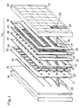
- FIG.1 shows an internal constitution of this picture display device of the prior art.
- numeral 101 is a back electrode
- numeral 102 represents linear cathodes as electron beam sources
- numeral 103 is an electron beam extraction electrode
- numeral 104 are signal electrodes
- numerals 105 and 106 are focusing electrodes
- numeral 107 is a horizontal deflection electrode
- numeral 108 is a vertical deflection electrode.
- the linear cathodes 102 are spanned in the horizontal direction so that they produce electron beams having horizontally uniform distribution, and a plural number of such linear cathodes 102 (here, only four of 102a to 102d are shown) are provided with an adequate spacing. These linear cathodes 102 are constituted by, for example, coating an oxide cathode material on the surface of tungsten wires.
- the back electrode 101 is composed of a planar conductive material, which is disposed in parallel with the linear cathodes 102a to 102d.
- the extraction electrode 103 counterfaces to the back electrode 101 having linear cathodes 102a to 102d therebetween, and it is composed of a conducting plate having arrays of through-holes 111 provided in the horizontal direction with an adequate spacing over horizontal lines counterfacing to respective linear cathodes.
- the signal electrodes 104 are composed of conducting plates 112 which are oblong in the vertical direction and disposed at positions respectively counterfacing to the through-holes on the extraction electrode 103 at a required distance, and at the positions counterfacing to the through-holes 111 of the extraction electrodes 103, similar through-holes 113 are present.
- the through-holes 113 may be oval or rectangular shaped, or also formed as a slit which is oblong in the vertical direction.
- the focusing electrode 105 is composed of a conducting plate having through-holes 114 at the positions respectively counterfacing to the through-holes 113 of the signal electrodes 104.
- the focusing electrode 106 has slit holes 116 which are extending vertically at the positions of through-holes 114 of the focusing electrode 105.
- the horizontal deflection electrode 107 is composed of two conducting comb-shaped plates 116 and 117 which are connected at their end parts and mutually engaged with keeping an adequate spacing over a single plane, and a space 118 formed between conducting plates 116 and 117 are facing to through-slit-holes 115 of the focusing electrode 106.
- the vertical deflection electrode 108 as shown in FIG.
- a screen 121 is constituted by coating, over the inner face of an envelope 109, a fluorescent material layer 122 which emits light by the illumination of electron beams and then by adding a metal-back layer (not shown in the figure) thereonto.
- the above-mentioned extraction electrode 103, signal electrode 104, focusing electrodes 105 and 106, horizontal deflection electrode 107, and vertical deflection electrode 108 are jointed respectively by an insulating adhesive (here, not shown in the figure), thereby an unity electrode block 124 is formed.
- the back electrode 101 In order to make the electron emission from the linear cathode 102 easy, it is heated by flowing a heater current. Under the state of heating, the back electrode 101, by impressing adequate voltages onto the linear cathodes 102 and the extraction electrode 103, sheet-shaped electron beams are emitted from the surface of the linear cathodes 102. The sheet-shaped electron beams are then divided into a plural number of electron beams by the through-holes 111 of the extraction electrode 103 and they become a plural number of electron beam flows 123. These electron beam flows 123 are adjusted on their passing amounts for respective electron beam flows by the signal electrodes 104 corresponding to the video signal impressed on the signal electrode 104.
- the electron beams passing through the signal electrodes 104 are focused and formed by the electrostatic lens effect of the through-holes 114 and 115 of the focusing electrodes 105 and 106, they are deflected by the potential differences given to the adjacent conducting plates 116 and 117 of the horizontal deflection electrode 107 as well as to the adjacent conducting plates 119 and 120 of the vertical deflection electrode 108. Furthermore, a high voltage (for example, 10 kV) is applied on the metal back layer of the screen 121, and hence the electron beams are accelerated up to a high energy and collide with the metal back to make the fluorescent material 122 emit light.
- a high voltage for example, 10 kV
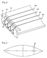
- the linear cathodes 102a to 102d are thin wires of a diameter of 10 ⁇ m, at their both ends (only one side is shown) their height is limited by a height limit bar 126, and their position in the Y direction is determined by a Y-direction positioning frame body 127. Furthermore, tension is given at both sides or at one side by springs 128 which are attached to the Y-direction positioning frame body 127.
- the linear cathodes 102a to 102d When vibration is applied to the picture display apparatus including positioned and spanned linear cathodes 102a to 102d, the linear cathodes 102a to 102d start vibration containing mainly the simple harmonic vibration as shown in FIG. 3 and keep this vibration unit it is damped out.
- the linear cathodes 102a to 102d vibrate, the amount of electron beams 123 passing through the through-holes 111 of the above-mentioned extraction electrode 103 varies periodically (not shown), and eventually the brightness on the screen varies periodically, hindering achieving stably a high quality picture image.
- cathode control lines 2 are spanned perpendicularly with respect to the spanning direction of linear cathodes 1, and they are held so as to keep a constant distance from the above-mentioned linear cathodes 1. Then, if a certain external force is applied to the structural body, although the above-mentioned linear cathodes start the vibration containing mainly the simple harmonic vibration, when they touch the cathode control line 2, the amplitude is controlled and damped, and thereby the vibration is suppressed.
- the above-mentioned cathode control wires 2 are disposed with predetermined intervals, not with a constant interval, and thereby, as shown in FIG.4, the resonant vibration due to the second-order vibration of the above-mentioned linear cathode 1 having its nodes at the above-mentioned cathode control lines 2 can be prevented.
- numeral 3 is an electrode
- numeral 4 is a height limit bar for the linear cathodes 1
- numeral 5 is a Y-direction positioning frame body for the linear cathodes 1
- numeral 6 are spring elements for spanning the linear cathodes 1 by giving tension thereon.
- the present invention is, in considering the problems described above, to offer a linear cathode apparatus which can stably emit one or plural electron beams and a picture display device which can display stably a high quality picture image all the time.
- the vibration prevention elements by being penetrated by the linear cathodes at their one end parts or both end parts, in case that vibrations of the above-mentioned linear cathodes occurs, immediately the above-mentioned vibration prevention elements start free motions, thereby the vibration energy is absorbed and hence the vibration of the above-mentioned linear cathodes is suppressed. And, since the above-mentioned vibration prevention elements are disposed outside the working picture area, and also they keep their contact to the above-mentioned linear cathodes, there is no dispersion on their vibration prevention function, and hence variation of brightness on the screen does not occur, thereby a stable high quality picture image can be offered.
- FIG.1 is an exploded perspective view of a picture display device on which the present invention is applied.
- FIG.2 is a perspective view of a part of spanning of linear cathodes of the above-mentioned picture display device.
- FIG.3 is a picture showing a vibration mode.
- FIG.4 is a partial perspective view showing one example of conventional linear cathode protection means.
- FIG.5 is a partial front view showing one example of conventional linear cathode protection means.
- FIG.6 is a picture showing a vibration mode in the conventional linear cathode protection means.
- FIG.7 is an exploded perspective view of principal part of a picture display device in one working example of the present invention.
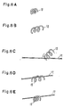
- FIGs.8A to E show a second working example of the present invention which are perspective views showing an installation procedure.
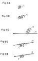
- FIGs.9A to E are perspective views showing a third working example of the present invention.
- FIGs.10A to E are perspective views showing a fourth working example of the present invention.
- FIGs.11A to E are perspective views showing a fifth working example of the present invention.
- FIGs.12A to E are perspective views showing a sixth working example of the present invention.
- FIG.13 is a perspective view showing a seventh working example of the present invention.
- FIG.14 is a whole perspective view showing an eighth working example of the present invention.
- FIG.15 is a perspective view of a principal part showing a ninth working example of the present invention.
- FIG.16 is a perspective view of a principal part showing a tenth working example of the present invention.
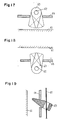
- FIG.17, FIG.18, and FIG.19 are cross-sectional views for explaining the function of the vibration prevention elements in the working example of FIG.16.
- FIG.7 On the picture display device of the first working example of the present invention, explanation is given using FIG.7.
- This first working example is devised in a manner that ring-shaped vibration prevention elements 13 (13a to 13d) made of inorganic material having a hole thereon are provided.
- the above-mentioned vibration prevention elements 13 are penetrated by all of a plural number of linear cathodes 12 (12a to 12d) at their one end parts or both end parts. Vibration of the linear cathodes 12 can be prevented by letting the vibration prevention elements 13 move freely responding to the vibration of the linear cathodes 12.
- FIG.7 shows only the configuration at one end parts of the linear cathodes 12, another end parts have the same configuration.
- numeral 11 is a back electrode
- numeral 12 are linear cathodes whose height is limited by height limit bars 15, and which are positioned in the Y-direction by a Y-direction positioning frame body 16.
- tension is given on respective linear cathodes 12a, 12b, 12c, and 12d by linear cathode springs 17, and thereby they are spanned.
- vibration prevention elements 13a, 13b, 13c and 13d made of inorganic material having a hole respectively are provided by being penetrated by the above-mentioned linear cathodes 12 outside the working picture area.
- the hole diameter of the vibration prevention elements 13 is far larger than the diameter of the linear cathodes 12, for example, for a diameter of the linear cathodes 13 of about 20 ⁇ m the hole diameter becomes about 400 ⁇ m.
- a frame body 14 having slots in the vertical direction of the above-mentioned linear cathodes 12 is provided.
- the linear cathodes 12 run through these slots.
- the above-mentioned vibration prevention elements 13a, 13b, 13c and 13d which are penetrated and provided on the above-mentioned linear cathodes 12a, 12b, 12c and 12d starts their free motion
- the vibration energy of the above-mentioned linear cathodes 12 is converted into the kinetic energy of the free motion of the above-mentioned vibration prevention elements 13, and the vibration of the above-mentioned linear cathodes 12 immediately damps and ceases.
- the above-mentioned vibration prevention elements 13 move on the above-mentioned linear cathodes 12 associated with their free motion, their positions are limited by the frame body 14 having slots. Therefore, it does not occur that the above-mentioned vibration prevention elements intrude into inside of the working picture area.
- FIG.8A shows a case that the above-mentioned vibration prevention element is a shape-memory alloy on which the shape of a coil is memorized beforehand, and also it shows the structure of attaching of the above-mentioned coil to the above-mentioned linear cathodes 12.
- FIG.8A shows a memorized shape of the coil 18 of the shape-memory alloy. Pulling the above-mentioned coil 18 of the shape-memory alloy in the coil axis direction, its wire spaces are expanded as shown in FIG.8B.
- the above-mentioned coil 18 of the shape-memory alloy are attached penetrated by twisting it onto the above-mentioned linear cathode 12 so that the above-mentioned all those wire spaces engage therewith.
- This situation is shown in FIGs.8C and 8D.
- the coil 18 of the shape memory alloy returns its original shape and its wire spaces become small, thereby the drop-off from the above-mentioned linear cathodes 12 can be prevented.
- FIG.8E On the vibration prevention of the above-mentioned linear cathodes 12 as well as the position limit of the above-mentioned coils 18 of shape memory alloy, they are the same as in the first working example.
- FIG.9 shows a case that the above-mentioned vibration prevention element is a coil 19 of shape-memory alloy on which a part in its peripheral direction is made touched, and also it shows the structure of attaching of the above-mentioned coil 19 to the above-mentioned linear cathode 12.
- FIG.9A shows a memorized shape of the coil 19 of the shape-memory alloy on which a part in its peripheral direction is made touched. Pulling the above-mentioned coil 19 of the shape-memory alloy on which a part in its peripheral direction is made touched in the coil axis direction, its wire spaces are expanded as shown in FIG.9B.
- the above-mentioned coil 19 of the shape-memory alloy is attached penetrated by twisting it onto the above-mentioned linear cathode 12 so that the above-mentioned all those wire spaces engage therewith. This situation is shown in FIGs.9C and 9D.
- FIG.9E On the vibration prevention of the above-mentioned linear cathodes 12 as well as the position limit of the above-mentioned coils 19 of shape-memory alloy, they are the same as in the first working example.
- FIG.10 shows a case that the above-mentioned vibration prevention element is a coil 20 of shape-memory alloy, and also it shows the structure of attaching of the above-mentioned coil to the above-mentioned linear cathode 12 after it is reversed.
- FIG.10A shows a memorized shape of the coil 20 of the shape-memory alloy. After reversing the above-mentioned coil 20 of shape memory alloy, pulling it in the coil axis direction, its wire spaces are expanded to form a reversed coil 20 of shape memory alloy. This situation is shown in FIG.10B.
- the above-mentioned coil 20 of the shape-memory alloy is attached penetrated by twisting it onto the above-mentioned linear cathode 12 so that all the wire spaces engage therewith. This situation is shown in FIGs.10C and 10D.
- FIG.10E On the vibration prevention of the above-mentioned linear cathodes 12 as well as the position limit of the above-mentioned reversed coil 20 of shape memory alloy, they are the same as in the first working example.
- FIG.11 shows a case that the above-mentioned vibration prevention element is a shape memory alloy on which the shape of a coil is memorized beforehand, and also it shows the structure of attaching of the above-mentioned coil 19 to the above-mentioned linear cathode 12 in case that the number of winding is taken to be one or two.
- FIG.11A shows a memorized shape of a tightly wound coil 21 of the shape memory alloy whose number of winding is taken to be one or two. Pulling the above-mentioned tightly wound coil 21 of the shape memory alloy in the coil axis direction, its wire spaces are expanded. This situation is shown in FIG.11B.
- FIG.12 shows an attaching structure to the above-mentioned linear cathodes 12 in a case that the above-mentioned vibration prevention element is a shape memory alloy on which the shape of a coil whose both end faces mutually touch is memorized beforehand.
- FIG.12A shows a memorized shape of a ring 22 of the shape memory alloy. Pulling the above-mentioned ring 22 of the shape memory alloy in the circumferential direction of the ring, its gap is expanded as shown in FIG.12B. Then inserting the above-mentioned ring 22 of the shape memory alloy into the above-mentioned linear cathode 12 through the above-mentioned gap between both end faces, thereby it is attached penetrated.
- the attaching structure to the above-mentioned linear cathodes 12 in case that the above-mentioned vibration prevention element is a coil of spring material on which a part in its peripheral direction is made touched is the same as in FIG.9. In this case, however, it is necessary to keep giving the above-mentioned coil of spring material a pulling tension in its axial direction during the penetration and attaching processings onto the above-mentioned linear cathodes 12.
- the attaching structure to the above-mentioned linear cathodes 12 in case that the above-mentioned vibration prevention element is a ring of spring material on which a part of its periphery is made touched is the same as in FIG.12. In this case, however, it is necessary to keep giving the above-mentioned ring of spring material a pulling tension in the its peripheral direction during the penetration and attaching processings onto the above-mentioned linear cathodes 12.
- the above-mentioned vibration prevention element is made of an insulating material or the same material as the above-mentioned linear cathode, it is the same as in the first working example.
- Ni/Ti alloy is, for the insulating inorganic material, ceramic is, and for the inorganic material same as that of the linear cathode, tungsten is, used, respectively.
- one ring-shaped vibration prevention element is penetrated to be attached on a linear cathode, and by letting the above-mentioned ring-shaped vibration prevention element the free movement, the vibration of the linear cathode is suppressed; and by penetrating an insulator wire through the hole of the above-mentioned ring-shaped vibration prevention element in a manner that it crosses perpendicularly with the above-mentioned linear cathode, and further by engaging the above-mentioned insulator wire with a plural number of position limit slots, the position control of the above-mentioned rings is made possible.
- FIG.13 shows only the configuration at one end parts of the linear cathodes 30, another end parts have the same configuration.
- numeral 29 is a back electrode.
- the linear cathodes 30 (30a to 30d) are limited on their height by height limit bars 34, and further they are positioned in the Y-direction by a Y-direction positioning frame body 35. And tension is given on respective linear cathodes 30a, 30b, 30c and 30d by linear cathode springs 36 and thereby they are spanned.
- ring-shaped vibration prevention elements 31a, 31b, 31c and 31d composed of inorganic and heat-resisting material are penetrated and provided.
- insulator wire 32 is made penetrated in a manner that it runs perpendicularly with respect to the above-mentioned linear cathodes 30.
- the above-mentioned insulator wire 32 is engaged with a plural number of limit slot elements 33a provided on insulator wire limit member 33.
- U-shaped insulator wire drop-off prevention elements 33b which are disposed on the above-mentioned insulator wire limit member 33 are provided, and thereby the drop-off of the above-mentioned insulator wire 32 is prevented.
- the insulator wire 32 a ceramic wire of a diameter of 15 ⁇ m is used, there is no restriction on its diameter or on the number of wires.
- the above-mentioned vibration prevention elements 31 move on the above-mentioned linear cathodes 30 associated with their free motion, their positions are limited by the above-mentioned insulator wire 32 which is inserted through the holes of the above-mentioned ring-shaped vibration prevention elements 31 as well as by limit slot elements 33a, and thereby intrusions of the above-mentioned ring-shaped vibration prevention elements 31 into the working picture area is prevented.
- the linear cathode spanning structure is disposed on a horizontal plane, even they are disposed on a vertical plane or on a plane with any angle, for the height of the limit slot elements 33a, by setting the slant angle, the effect of the vibration prevention of the above-mentioned linear cathodes 30 as well as the position limit of the above-mentioned ring-shaped vibration prevention elements 31 can be held.
- the number of the ring-shaped vibration prevention elements 31 was one, it is also possible to use a plural number of them.
- FIG.14 an eighth working example of the present invention is shown,
- numeral 41 is a back electrode, and both ends of the linear cathodes 43 are fixed on fixing stands 42.
- this fixing means is the same as in the first working example.
- Numeral 44 are vibration prevention elements, which are composed of a piece of short-cut ultra-thin ceramic insulator tube, and for each linear cathode 43 two thereof are provided on both end parts by inserting them thereon to be attached.
- Numeral 45 are stoppers for stopping the movement of the vibration prevention elements 44 provided on the back electrode 41, which are for preventing the movement of the vibration prevention elements 44 into the working picture area in association with the vibration of the linear cathodes 44. These stoppers 45 are made in such a height that they do not let the vibration prevention elements 44 pass there-over and also they do not touch the linear cathodes 43.
- FIG.15 a ninth working example of the present invention is shown,
- This working example is the one that is provided with structural elements which are made of insulating material as the vibration prevention elements and composed of two connected rings, and these vibration prevention elements are penetrated and attached on the both end parts of respective linear cathodes. And, it is devised such that the vibration of the linear cathodes is prevented by inserting wires between a plural number of linear cathodes and connecting parts of two rings in a manner that they positions perpendicularly with respect to the linear cathodes.
- numeral 51 is a back electrode
- 52a, 52b, 52c and 52d are linear cathodes.
- 53a 53b 53c and 53d are double-rings which are of ceramics of two rings connected to each other
- numeral 54 is an insulator wire made of a glass fiber of a diameter of 50 ⁇ m
- numeral 55 is a height limit bar
- numeral 56 is a Y-direction positioning frame body
- numeral 57 are linear cathode spanning springs.
- Numeral 58 are fixing stands for fixing the both ends of the insulator wire 54.
- FIG.15 although only the structure of one end part of the linear cathodes 52 is shown, another end part has the same structure.
- the linear cathodes 52 are limited on their height by height limit bars 55, and further they are positioned in the Y-direction by a Y-direction positioning frame body 56. And tension is given on respective linear cathodes 52a, 52b, 52c and 52d by linear cathode springs 57 and thereby they are spanned. And holes of those two rings of the double-rings 53a, 53b, 53c and 53d are penetrated with the linear cathodes 52a, 52b, 52c and 52d.
- an insulating wire 54 is inserted and provided between the connecting parts 59a, 59b, 59c and 59d of the double-rings 53 and the linear cathodes 52a, 52b, 52c and 53d in a manner that they positions perpendicularly with respect to the linear cathodes 52.
- Both of the height limit bar 55 and the Y-direction positioning frame body 56 are made of insulator material (in the present working example, ceramics is used). Therefore, linear cathodes 52a, 52b, 52c and 52d are respectively insulated.
- the insulator wire 54 is fixed by at its both end parts by the fixing stands 58.
- linear cathodes 52a, 52b, 52c and 52d start vibrations at their respective eigen frequencies.
- the above-mentioned double-rings 53a, 53b, 53c and 53d penetrated and attached on linear cathodes 52a, 52b, 52c and 52d start their free motion, the vibration energy of the above-mentioned linear cathodes 52 is converted into the kinetic energy of the free motion of the above-mentioned double-ring vibration prevention elements 53, and the vibration of the above-mentioned linear cathodes 52 immediately damps and ceases.
- the above-mentioned double-rings 53 are about to move on the above-mentioned linear cathodes 52 associated with their free motion, their positions are limited by the above-mentioned insulator wire 54 which is inserted between the the double-rings 53 and the above-mentioned linear cathodes 52, as well as by the fixing stands 58, and thereby intrusions of the above-mentioned double-rings 53 into the working picture area is prevented.
- the linear cathode spanning structure is disposed on a horizontal plane, even they are disposed on a vertical plane or on a plane with any angle, the above-mentioned vibration prevention effect and the position limit effect are kept the same.
- FIG.16 a tenth working example of the present invention is shown,
- This working example is the one that is provided with vibration prevention elements made of an insulating material and having a hole at a position eccentric from the center of gravity thereof.
- the above-mentioned holes of the vibration prevention elements are penetrated by the linear cathodes, thereby the vibration prevention elements are attached.
- numeral 61 is a back electrode
- 62a, 62b, 62c and 62d are linear cathodes
- 63a, 63b, 63c and 63d are eccentric rings which are vibration prevention elements composed of an insulating material and having a hole at a position displaced from the center of gravity thereof (in the working example, ceramics is used)
- numeral 64 is a limit member
- numeral 64a are limit holes provided on the limit member 64
- numeral 65 is a height limit bar
- numeral 66 is a Y-direction positioning frame body
- numeral 67 are linear cathode springs.
- linear cathodes 62 are limited on their height by height limit bars 65, and further they are positioned in the Y-direction by a Y-direction positioning frame body 66. And tension is given on respective linear cathodes 62a, 62b, 62c and 62d by linear cathode springs 67 and thereby they are spanned. And respective linear cathodes 62a, 62b, 62c and 62d penetrate the hole parts of the eccentric rings 63a, 63b, 63c and 63d.
- both of the height limit bars 65 and the Y-direction positioning frame body 66 are either made of an insulating material (in the working example, ceramics is used). Consequently, those linear cathodes 62a, 62b, 63c and 52d are insulated respectively.
- linear cathodes 62a, 62b, 62c and 62d start vibrations at their respective eigen frequencies.
- FIG.17 although the linear cathode spanning structure is disposed on a horizontal plane, even they are disposed on a vertical plane or on a plane with any angle as in FIG.19, the above-mentioned vibration prevention effect and the position limit effect are kept the same.
- FIG.18 shows a case that an eccentric ring 63 is attached upside down with respect to the case in FIG.17.
- vibration prevention elements at one end part or at both end parts of linear cathodes, when vibrations of the above-mentioned linear cathodes take place due to an external force onto a picture display device the above-mentioned vibration prevention elements start their free motions, and hence they absorb the vibration energy and thereby the vibrations of the above-mentioned linear cathodes are suppressed.
Landscapes
- Cathode-Ray Tubes And Fluorescent Screens For Display (AREA)
- Electrodes For Cathode-Ray Tubes (AREA)
Abstract
Claims (17)
- Appareil à cathodes linéaires comprenant :
une contre-électrode (11; 29; 41; 51;61) s'étendant suivant un premier plan ;
au moins une cathode linéaire (12; 30; 43; 52; 62) placée suivant ladite contre-électrode dans un plan parallèle audit premier plan ;
un moyen de maintien (15) pour maintenir ladite cathode linéaire à une hauteur prédéterminée au-dessus d'une surface de ladite contre-électrode ; et
au moins un élément empêchant les vibrations (13; 18; 19; 20; 21; 22; 31; 44; 53; 63) formé de matériaux inorganiques ayant des surfaces internes définissant un trou pour faire passer ladite cathode linéaire (12; 30; 43; 52; 62) à travers celui-ci, chaque dit élément empêchant les vibrations (13; 18; 19; 20; 21; 22; 31; 44; 53; 63) étant engagé avec chaque dite cathode linéaire à une première partie d'extrémité de ladite cathode linéaire ;
caractérisé en ce que :
chaque dit élément empêchant les vibrations (13; 18; 19; 20; 21; 22; 31; 44; 53; 63) est librement engagé autour de chaque dite cathode linéaire (12; 30; 43; 52; 62) avec seulement le poids dudit élément empêchant les vibrations le maintenant sur ladite cathode linéaire afin de lui permettre son mouvement libre et comprenant de plus :
un moyen de limitation (14; 33; 45; 58; 64) pour limiter l'étendue dudit mouvement libre dudit élément empêchant les vibrations (13; 18; 19; 20; 21; 22; 31; 44; 53; 63) dans une direction suivant laquelle ladite cathode linéaire s'étend, à l'intérieur de limites prédéterminées à l'extérieur d'une zone image utile. - Appareil à cathodes linéaires selon la revendication 1, dans lequel
ledit au moins un élément empêchant les vibrations (18; 19) est constitué d'un alliage à mémoire de forme dans lequel une forme de bobine est mémorisée précédemment. - Appareil à cathodes linéaires selon la revendication 2, dans lequel
ladite bobine (19) présente une partie à contact serré dans la direction périphérique. - Appareil à cathodes linéaires selon la revendication 2, dans lequel
ledit élément empêchant les vibrations (20) présente une forme ayant une forme inversée de ladite forme de bobine. - Appareil à cathodes linéaires selon la revendication 3, dans lequel
le nombre de tours de ladite forme de bobine est de un ou de deux. - Appareil à cathodes linéaires selon la revendication 2, dans lequel
ledit élément empêchant les vibrations (22) est un alliage à mémoire de forme d'une forme d'anneau dont les deux parties d'extrémité se contactent mutuellement de manière très serrée. - Appareil à cathodes linéaires selon la revendication 1, dans lequel
ledit élément empêchant les vibrations est une bobine (22) constituée d'un matériau élastique incluant une partie à contact serré. - Appareil à cathodes linéaires selon la revendication 1, dans lequel
ledit élément empêchant les vibrations (19, 21, 22) est un anneau d'un matériau élastique dont les deux extrémités sont mutuellement en contact serré. - Appareil à cathodes linéaires selon la revendication 1, dans lequel
ledit élément empêchant les vibrations (13; 18; 19; 20; 21; 22; 31; 44; 53; 63) est un matériau parmi les matériaux isolants. - Appareil à cathodes linéaires selon la revendication 2, dans lequel
ledit élément empêchant les vibrations (18; 19) est du même matériau que celui de ladite cathode linéaire (12). - Appareil à cathodes linéaires selon la revendication 1, dans lequel
ledit élément empêchant les vibrations est un élément en forme d'anneau (31a, b, c, d) et
ledit moyen de limitation comprend un fil isolant (32), qui passe à travers la totalité desdits éléments empêchant les vibrations (31a à d) dans une direction perpendiculaire (Y) à ladite direction dans laquelle ladite cathode linéaire (30a à d) s'étend, et un élément de limitation de fil isolant (33) ayant une multitude de fentes de limitations de position (33a) qui sont traversées par ledit fil isolant (32). - Appareil à cathodes linéaires selon la revendication 1, dans lequel
chacun desdits éléments empêchant les vibrations (53a à d) est constitué d'un matériau isolant et est constitué par deux anneaux, à travers lesquels chacune desdites cathodes linéaires (52a à d) passe, et un élément de raccord (59a à d) pour raccorder lesdits deux anneaux, et
ledit moyen de limitation comprend un fil isolant (54) qui passe à travers la totalité des espaces formés chacun entre lesdits deux anneaux dans la direction perpendiculaire (Y) par rapport auxdites cathodes linéaires (52a à d). - Appareil à cathodes linéaires selon la revendication 1, dans lequel
chacun desdits éléments empêchant les vibrations (63a à d) est formé d'un matériau isolant ayant ledit trou à une position excentrique par rapport à son centre de gravité, et
ledit moyen de limitation comprend un élément de limitation de position (64) ayant un ou une multitude de trous de limitation (64a) correspondant auxdits éléments empêchant les vibrations (63a à d), et
chacun desdits éléments empêchant les vibrations (63a à d) est engagé avec le trou correspondant parmi lesdits trous de limitation (64) avec un des battements appropriés entre ceux-ci. - Dispositif d'affichage d'image comprenant :
une enveloppe en verre de face avant (109) dont la surface interne est revêtue d'un matériau fluorescent ; et
une enveloppe de face arrière en regard (110) dans une direction opposée à ladite enveloppe en verre de face avant ; et
une structure entre ladite enveloppe en verre de face avant (109) et ladite enveloppe de face arrière (110) comprenant :
une contre-électrode (11; 29; 41; 51; 61) composée d'une plaque conductrice ;
au moins une cathode linéaire (12; 30; 43; 52; 62) placée dans une direction suivant ladite contre-électrode ;
au moins un élément empêchant les vibrations (13; 18; 20; 21; 22; 31; 44; 53; 63) formé de matériaux inorganiques et ayant des surfaces internes définissant un trou pour passer ladite cathode linéaire à travers celui-ci, chaque dit élément empêchant les vibrations étant traversé par chaque dite cathode linéaire à une première partie d'extrémité de ladite cathode linéaire ;
une électrode d'extraction (103) composée d'au moins une plaque conductrice ;
une électrode de signal (104) composée d'au moins une plaque conductrice ;
une électrode de focalisation (105; 106) composée d'au moins une plaque conductrice ;
une électrode de déviation horizontale (107) composée d'au moins une plaque conductrice ; et
une électrode de déviation verticale (108) composée d'au moins une plaque conductrice ;
caractérisé en ce que
chaque dit élément empêchant les vibrations (13; 18; 19; 20; 21; 22; 31; 44; 53; 63) est librement engagé autour de chaque cathode linéaire (12; 30; 43; 52; 62) avec seulement le poids dudit élément empêchant les vibrations la maintenance sur ladite cathode linéaire afin de permettre son mouvement libre et comprenant de plus :
un moyen de limitation (14; 33; 45; 58; 64, pour limiter l'étendue dudit mouvement libre dudit élément empêchant les vibrations (13; 18; 19; 20; 21; 22; 31; 44; 53; 63) dans ne direction suivant laquelle ladite cathode linéaire (12; 30; 43; 52; 62), s'étend à l'intérieur de limites prédéterminées à l'extérieur de la zone image utile. - Dispositif d'affichage d'image selon la revendication 14, dans lequel
chacun desdits éléments empêchant les vibrations (31a à d) comporte au moins un anneau, et
ledit moyen de limitation (33) comprend un fil isolant (32), qui passe à travers la totalité desdits éléments empêchant les vibrations (31a à d) dans une direction perpendiculaire (Y) par rapport auxdites cathodes linéaires (30a à d), et un élément de limitation de fil isolant (33) ayant une multitude de fentes de limitation de position (33a) qui sont traversées par le fil isolant. - Dispositif d'affichage d'image selon la revendication 14, dans lequel
chacun desdits éléments empêchant les vibrations (53a à d) est formé d'un matériau isolant et constitué par deux anneaux, à travers lesquels lesdites cathodes linéaires (52a à d) passent, et un élément de raccord (59a à d) pour raccorder lesdits deux anneaux, et
ledit moyen de limitation comprend un fil isolant (54) qui passe à travers la totalité des espaces, chacun formé entre lesdits deux anneaux dans une direction perpendiculaire (Y) par rapport auxdites cathodes linéaires (52a à d). - Dispositif d'affichage d'image selon la revendication 14, dans lequel
chacun desdits éléments empêchant les vibrations (63a à d) est constitué d'un matériau isolant ayant ledit trou à une position excentrée par rapport à son centre de gravité,
ledit moyen de limitation comprend un élément de limitation de position (64) comportant un ou une multitude de trous de limitation (64a) correspondant auxdits éléments empêchant les vibrations (63a à d), et
chacun desdits éléments empêchant les vibrations (63a à d) est engagé avec le trou de limitation correspondant parmi lesdits trous de limitation (64a) avec un débattement approprié à celui-ci.
Applications Claiming Priority (7)
| Application Number | Priority Date | Filing Date | Title |
|---|---|---|---|
| JP154689A JP2776527B2 (ja) | 1989-01-06 | 1989-01-06 | 画像表示装置 |
| JP1546/89 | 1989-01-06 | ||
| JP62462/89 | 1989-03-15 | ||
| JP6246289A JP2778089B2 (ja) | 1989-03-15 | 1989-03-15 | 画像表示装置 |
| JP11534489A JP2943158B2 (ja) | 1989-05-09 | 1989-05-09 | 画像表示装置 |
| JP115344/89 | 1989-05-09 | ||
| PCT/JP1989/001317 WO1990007788A1 (fr) | 1989-01-06 | 1989-12-28 | Dispositif d'affichage d'images |
Publications (3)
| Publication Number | Publication Date |
|---|---|
| EP0406441A1 EP0406441A1 (fr) | 1991-01-09 |
| EP0406441A4 EP0406441A4 (en) | 1991-12-04 |
| EP0406441B1 true EP0406441B1 (fr) | 1995-11-08 |
Family
ID=27274966
Family Applications (1)
| Application Number | Title | Priority Date | Filing Date |
|---|---|---|---|
| EP90901008A Expired - Lifetime EP0406441B1 (fr) | 1989-01-06 | 1989-12-28 | Dispositif d'affichage d'images |
Country Status (4)
| Country | Link |
|---|---|
| US (1) | US5192892A (fr) |
| EP (1) | EP0406441B1 (fr) |
| DE (1) | DE68924770T2 (fr) |
| WO (1) | WO1990007788A1 (fr) |
Families Citing this family (9)
| Publication number | Priority date | Publication date | Assignee | Title |
|---|---|---|---|---|
| EP0406441B1 (fr) * | 1989-01-06 | 1995-11-08 | Matsushita Electric Industrial Co., Ltd. | Dispositif d'affichage d'images |
| US5444258A (en) * | 1992-08-24 | 1995-08-22 | Societe Europeenne De Propulsion | Ion-optics system for a source of ions to be discharged into a gas |
| WO1994005032A1 (fr) * | 1992-08-24 | 1994-03-03 | Societe Europeenne De Propulsion, S.A. | Systeme d'optique ionique pour une source d'ions a decharge dans un gaz |
| JP3051276B2 (ja) * | 1993-01-22 | 2000-06-12 | 双葉電子工業株式会社 | 蛍光表示管および蛍光表示管用Re−W材 |
| FR2716573B1 (fr) * | 1994-02-24 | 1996-05-03 | Europ Propulsion | Système d'optique ionique à trois grilles. |
| JPH11312480A (ja) * | 1998-04-28 | 1999-11-09 | Matsushita Electron Corp | 平板状画像表示装置 |
| KR100459953B1 (ko) * | 2001-02-20 | 2004-12-04 | 후다바 덴시 고교 가부시키가이샤 | 전자관과 그 제조 방법 |
| JP3929979B2 (ja) * | 2004-01-20 | 2007-06-13 | 双葉電子工業株式会社 | 電子管 |
| JP4216764B2 (ja) * | 2004-05-21 | 2009-01-28 | 株式会社日立製作所 | ディスプレイ装置並びにディスプレイモジュール及びディスプレイパネル |
Family Cites Families (12)
| Publication number | Priority date | Publication date | Assignee | Title |
|---|---|---|---|---|
| US1155460A (en) * | 1914-11-13 | 1915-10-05 | Standard Underground Cable Company | Armor for flexible articles. |
| US3246073A (en) * | 1960-10-06 | 1966-04-12 | Bouche | Vibration damper for suspended outdoor wires |
| US3772718A (en) * | 1971-08-16 | 1973-11-20 | Preformed Line Products Co | Cable indicating, flotation and vibration damping devices |
| JPS547585A (en) * | 1977-06-20 | 1979-01-20 | Nippon Telegr & Teleph Corp <Ntt> | Vibration-proof cable |
| US4714863A (en) * | 1984-08-30 | 1987-12-22 | Matsushita Electric Industrial Co., Ltd. | Vibration damping means for the line cathodes of an image display apparatus |
| JPS61267240A (ja) * | 1985-05-21 | 1986-11-26 | Matsushita Electric Ind Co Ltd | 平板形映像管 |
| JPS61230239A (ja) * | 1985-04-03 | 1986-10-14 | Matsushita Electric Ind Co Ltd | 平板形映像管 |
| US4812716A (en) * | 1985-04-03 | 1989-03-14 | Matsushita Electric Industrial Co., Ltd. | Electron beam scanning display apparatus with cathode vibration suppression |
| US4680424A (en) * | 1985-12-06 | 1987-07-14 | Aluminum Company Of America | Overhead conductor damping device with die cast components and method of making the same |
| NL8800423A (nl) * | 1988-02-19 | 1989-09-18 | Philips Nv | Beeldweergeefapparaat voorzien van een vlak beeldvenster en microfoniearme lijnvormige thermische draadkathodes. |
| EP0406441B1 (fr) * | 1989-01-06 | 1995-11-08 | Matsushita Electric Industrial Co., Ltd. | Dispositif d'affichage d'images |
| JPH0510958A (ja) * | 1991-07-02 | 1993-01-19 | Olympus Optical Co Ltd | 分析装置 |
-
1989
- 1989-12-28 EP EP90901008A patent/EP0406441B1/fr not_active Expired - Lifetime
- 1989-12-28 US US07/576,469 patent/US5192892A/en not_active Expired - Lifetime
- 1989-12-28 WO PCT/JP1989/001317 patent/WO1990007788A1/fr not_active Ceased
- 1989-12-28 DE DE68924770T patent/DE68924770T2/de not_active Expired - Fee Related
Also Published As
| Publication number | Publication date |
|---|---|
| DE68924770D1 (de) | 1995-12-14 |
| DE68924770T2 (de) | 1996-06-13 |
| WO1990007788A1 (fr) | 1990-07-12 |
| EP0406441A4 (en) | 1991-12-04 |
| US5192892A (en) | 1993-03-09 |
| EP0406441A1 (fr) | 1991-01-09 |
Similar Documents
| Publication | Publication Date | Title |
|---|---|---|
| US5192892A (en) | Picture display device with a vibration-preventing element | |
| JPH08190877A (ja) | 陰極線管 | |
| US3735190A (en) | Color cathode ray tube | |
| EP1233439B1 (fr) | Tube cathodique | |
| JP3546729B2 (ja) | 電子銃、電子銃の製造方法、陰極線管装置 | |
| US4714863A (en) | Vibration damping means for the line cathodes of an image display apparatus | |
| US6329747B1 (en) | Cathode ray tube having an overall length thereof shortened | |
| JP2874229B2 (ja) | 画像表示装置 | |
| US3421048A (en) | Color-selection mask and post-deflection focus assembly for a color tube | |
| US6133683A (en) | Color cathode ray tube having an internal voltage divider | |
| US3529196A (en) | Cathode ray tube with axially separable tube means for mounting the electrodes therein | |
| US2867749A (en) | Color television | |
| US6566799B1 (en) | Cathode ray tubes having damper wire support springs | |
| JP2778089B2 (ja) | 画像表示装置 | |
| JP2563282B2 (ja) | 平板形陰極線管 | |
| KR100728191B1 (ko) | 음극선관용 전자총 | |
| US3321655A (en) | Photoconductive pickup tube field mesh support | |
| KR100431261B1 (ko) | 편향요크 | |
| GB750644A (en) | Improvements in or relating to electron beam convergence systems for cathode ray tubes | |
| JPS61267240A (ja) | 平板形映像管 | |
| JPH02270252A (ja) | 電子源 | |
| JPS5994334A (ja) | 平板形陰極線管 | |
| JPH02160345A (ja) | 画像表示装置 | |
| KR0177702B1 (ko) | 새도우마스크형 칼라수상관 | |
| KR930007368B1 (ko) | 화상표시장치에 있어서의 전자비임의 제어방법 |
Legal Events
| Date | Code | Title | Description |
|---|---|---|---|
| PUAI | Public reference made under article 153(3) epc to a published international application that has entered the european phase |
Free format text: ORIGINAL CODE: 0009012 |
|
| 17P | Request for examination filed |
Effective date: 19900904 |
|
| AK | Designated contracting states |
Kind code of ref document: A1 Designated state(s): DE FR GB |
|
| A4 | Supplementary search report drawn up and despatched |
Effective date: 19911014 |
|
| AK | Designated contracting states |
Kind code of ref document: A4 Designated state(s): DE FR GB |
|
| 17Q | First examination report despatched |
Effective date: 19940118 |
|
| GRAA | (expected) grant |
Free format text: ORIGINAL CODE: 0009210 |
|
| AK | Designated contracting states |
Kind code of ref document: B1 Designated state(s): DE FR GB |
|
| REF | Corresponds to: |
Ref document number: 68924770 Country of ref document: DE Date of ref document: 19951214 |
|
| ET | Fr: translation filed | ||
| PLBE | No opposition filed within time limit |
Free format text: ORIGINAL CODE: 0009261 |
|
| STAA | Information on the status of an ep patent application or granted ep patent |
Free format text: STATUS: NO OPPOSITION FILED WITHIN TIME LIMIT |
|
| 26N | No opposition filed | ||
| REG | Reference to a national code |
Ref country code: GB Ref legal event code: IF02 |
|
| PGFP | Annual fee paid to national office [announced via postgrant information from national office to epo] |
Ref country code: FR Payment date: 20021210 Year of fee payment: 14 |
|
| PGFP | Annual fee paid to national office [announced via postgrant information from national office to epo] |
Ref country code: GB Payment date: 20021224 Year of fee payment: 14 |
|
| PGFP | Annual fee paid to national office [announced via postgrant information from national office to epo] |
Ref country code: DE Payment date: 20030109 Year of fee payment: 14 |
|
| PG25 | Lapsed in a contracting state [announced via postgrant information from national office to epo] |
Ref country code: GB Free format text: LAPSE BECAUSE OF NON-PAYMENT OF DUE FEES Effective date: 20031228 |
|
| PG25 | Lapsed in a contracting state [announced via postgrant information from national office to epo] |
Ref country code: DE Free format text: LAPSE BECAUSE OF NON-PAYMENT OF DUE FEES Effective date: 20040701 |
|
| GBPC | Gb: european patent ceased through non-payment of renewal fee |
Effective date: 20031228 |
|
| PG25 | Lapsed in a contracting state [announced via postgrant information from national office to epo] |
Ref country code: FR Free format text: LAPSE BECAUSE OF NON-PAYMENT OF DUE FEES Effective date: 20040831 |
|
| REG | Reference to a national code |
Ref country code: FR Ref legal event code: ST |