EP0406451A1 - Propulseur maritime - Google Patents
Propulseur maritime Download PDFInfo
- Publication number
- EP0406451A1 EP0406451A1 EP90901906A EP90901906A EP0406451A1 EP 0406451 A1 EP0406451 A1 EP 0406451A1 EP 90901906 A EP90901906 A EP 90901906A EP 90901906 A EP90901906 A EP 90901906A EP 0406451 A1 EP0406451 A1 EP 0406451A1
- Authority
- EP
- European Patent Office
- Prior art keywords
- propeller
- blades
- turbine blades
- turbine
- diameter
- Prior art date
- Legal status (The legal status is an assumption and is not a legal conclusion. Google has not performed a legal analysis and makes no representation as to the accuracy of the status listed.)
- Granted
Links
Images








Classifications
-
- B—PERFORMING OPERATIONS; TRANSPORTING
- B63—SHIPS OR OTHER WATERBORNE VESSELS; RELATED EQUIPMENT
- B63H—MARINE PROPULSION OR STEERING
- B63H5/00—Arrangements on vessels of propulsion elements directly acting on water
- B63H5/07—Arrangements on vessels of propulsion elements directly acting on water of propellers
- B63H5/08—Arrangements on vessels of propulsion elements directly acting on water of propellers of more than one propeller
- B63H5/10—Arrangements on vessels of propulsion elements directly acting on water of propellers of more than one propeller of coaxial type, e.g. of counter-rotative type
-
- B—PERFORMING OPERATIONS; TRANSPORTING
- B63—SHIPS OR OTHER WATERBORNE VESSELS; RELATED EQUIPMENT
- B63H—MARINE PROPULSION OR STEERING
- B63H1/00—Propulsive elements directly acting on water
- B63H1/02—Propulsive elements directly acting on water of rotary type
- B63H1/12—Propulsive elements directly acting on water of rotary type with rotation axis substantially in propulsive direction
- B63H1/14—Propellers
- B63H1/28—Other means for improving propeller efficiency
-
- B—PERFORMING OPERATIONS; TRANSPORTING
- B63—SHIPS OR OTHER WATERBORNE VESSELS; RELATED EQUIPMENT
- B63H—MARINE PROPULSION OR STEERING
- B63H5/00—Arrangements on vessels of propulsion elements directly acting on water
- B63H5/07—Arrangements on vessels of propulsion elements directly acting on water of propellers
- B63H5/08—Arrangements on vessels of propulsion elements directly acting on water of propellers of more than one propeller
- B63H5/10—Arrangements on vessels of propulsion elements directly acting on water of propellers of more than one propeller of coaxial type, e.g. of counter-rotative type
- B63H2005/103—Arrangements on vessels of propulsion elements directly acting on water of propellers of more than one propeller of coaxial type, e.g. of counter-rotative type of co-rotative type, i.e. rotating in the same direction, e.g. twin propellers
Definitions
- the present invention relates to a device for propelling ships.
- Ship propelling devices include a tandem propeller device comprising at least two propellers mounted on a propeller shaft and spaced apart longitudinally of the shaft (Unexamined Japanese Patent Publication SHO 57-205297), a tandem propeller device comprising front and rear propellers which are different in diameter (Unexamined Japanese Utility Model Publications SHO 56-30195 and SHO 57-139500), finned propeller boss cap (Unexamined Japanese Patent Publication SHO 63-154494), etc.
- the velocity induced by the front propeller is in such a direction as to accelerates the water flowing rearwardly of the propeller and also moves the water in the same direction as the rotation of the propeller, consequently giving a lower efficiency to the rear propeller which operates in the rearward flow produced by the front propeller. It has therefore been difficult to improve the propeller efficiency of the tandem propeller device.
- the tandem propeller device will be described generally with reference to FIGS. 9 to 11 and FIGS. 30 and 31.
- FIG. 9 is a diagram showing a propeller blade as it is seen from the rudder side.
- R is the radius of the propeller
- r is an optional radial position.
- FIG. 10 shows the propeller blade in section taken along a cylinder with the radius r and developed to a plane.
- the propeller blade has a pitch like screws and a pitch angle 9 with respect to the direction of rotation. (The pitch surface is defined by the so- leading called nose-tail line through the edge of the blade trailing and the edge thereof.) Further the blade has a camber forwardly of the propeller as seen in the cross section of FIG. 11.
- the lift L acts perpendicular to the direction of inflow of water, and the component thereof in the direction of advance is a thrust T, and the component thereof in the direction of rotation is a rotation resistance force F.
- the tandem propeller will be discussed.
- the front propeller is positioned in front of the rear propeller and is therefore subjected to the velocity induced by the rear propeller, so that 3i is slightly greater, i.e., Bi' as shown in FIG. 30.
- Bi' the velocity induced by the rear propeller
- the rear propeller which is positioned in the rearward flow from the front propeller, is subjected to the velocity induced by the front propeller (the propeller-induced velocity increases due to acceleration as the water flows rearward) and further to the velocicy induced by the rear propeller itself, with the result that si becomes greater, i.e., si" as shown in FIG. 31.
- the rotational torque delivered from the engine may be absorbed by the combination of the front and rear propellers, while the diameter, pitch, etc. of the front and rear propellers are variable. Accordingly, although some conclusion as to the improvement of efficiency can not be obtained only from the above explanation, it is apparent that the induced velocities of the front and rear propellers adversely affect each other to make it difficult to achieve an improved propeller efficiency.
- FIGS. 20 and 21 solid curves represent the values obtained according to the propeller lifting surface theory and the propeller theory of infinite number of blades for a propeller speeds designed for ships of medium when the propeller is in rotation in a uniform flow.
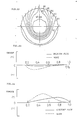
- FIG. 20 shows a distribution of propeller-induced velocities at the position of the propeller along the radial direction thereof.
- Wx is the velocity of a propeller-induced flow which is drawn into the propeller and forced out rearwardly thereof
- W ⁇ is the velocity of a propeller-induced flow which is produced in the same direction as the propeller rotation. It is seen that boch Wx and W ⁇ increase greatly at the position of the propeller.
- FIG. 22 shows the wake distribution of ships of medium speed.
- FIGS. 20 and 21 broken curves represent calculated propeller-induced velocities when the propeller is in rotation in the wake. It is seen that over the r/R range of 0.2 to 0.6 in which the wake is great, the propeller-induced velocity is much higher in the wake than in the uniform flow.
- FIGS. 23 and 24 show the radial distributions of decreases in the thrust and increases in the rotation resistance torque, respectively, corresponding to the propeller-induced velocities of FIG. 20 (as calculated based on the propel- lter lifting surface theory).
- the solid line represents the result in the uniform flow, and the broken line the result in the wake.
- the decrease in the thrust due to the propeller-induced velocity is 4% of the propeller thrust in the uniform flow but is as great as 10% of the thrust in the wake.
- the increase in the rotation resistance torque due to the induced velocity is 21% of the whole in the uniform flow but is as great as 28% in the wake.
- FIGS. 23 and 24 indicate that the decrease and increase concentrically occur in the r/R range of 0.2 to 0.6 where the wake is great.
- the finned propeller boss cap (hereinafter referred to briefly as "PBCF") disclosed in Unexamined Japanese Patent Publication SHO 63-154494 comprises a propeller boss cap having fins.
- the fins act as plates for guiding the water flow in the rear of the propeller boss cap toward such a direction as to inhibit hub vortices, diffusing hub vortices to decrease the drag induced by vortices on the propeller blades.
- the propeller efficiency is dependent on the propeller-induced velocity, especially that in the uneven stern wake, as already stated. Accordingly, the effect expected of the PBCF can not be fully achieved unless the problem associated with the induced velocity is solved.
- a first object of the present invention which has been accomplished to solve the foregoing problems of the prior art is to provide turbine blades in the rear of propeller blades to realize an improved propeller efficiency and a reduced torque.
- the propeller basically differs from the turbine in that the former is a device for giving energy to a fluid to obtain a propelling force from the resulting reaction, whereas the latter is a device for obtaining a rotational torque from the energy possessed by a fluid.
- the velocities induced by the two devices are in exactly opposite directions to each other. We have attained the above first object directing attention to this basic difference.
- a second object of the present invention is to provide a ship propelling device comprising turbine blades disposed in the rear of propeller blades, the turbine blades being prepared separately from a propeller boss and a propeller cap and removably provided on the propeller boss or between the boss and the propeller cap, the propelling device therefore being so adapted that an existing cap is usable as it is for an existing propeller.
- the present invention provides the following technical means.
- the present invention provides a ship propelling device having mounted on a propeller shaft 1 propeller blades 2 and turbine blades 3,-the device being characterized in that the propeller blades 2 are arranged at a front position with the turbine blades arranged at a rear position, the axial distance 2 between both the blades 2, 3 being at least 6%, the number of turbine blades 3 being the number of propeller blades 2 multiplied by an integer, the diameter of the turbine blades 3 being 33 to 60% of the diameter of the propeller blades 2.
- the axial distance A is a value (%) obtained by dividing the distance between the center lines of the respective blades 2, 3 by the diameter of the propeller.
- the pitch angle ⁇ P of the propeller blades 2 and the pitch angle ⁇ T of the turbine blades 3 satisfy the relation of ⁇ T ⁇ ⁇ P + 20° at a position of 0.3 5 ⁇ r/R ⁇ 0.6, whereby the first object is achieved.
- the presenc invention provides the following technical means.
- the device is characterized in that the turbine blades 3 disposed in the rear of the propeller blades 2 each have a flange 13A at the base portion thereof, the flange 13A being removably fastened to the outer periphery of a propeller boss 2A with screws.
- the device is characterized in that the turbine blades 3 disposed in the rear of the propeller blades 2 have a ring 3A at their base portions, the ring 3A being removably fixedly interposed between a propeller boss 2A and a propeller cap 4 in the rear of the boss 2A.
- the device is further characterized in that the turbine blades 3 are formed integrally with the ring 3A.
- the device is characterized in that the turbine blades 3 are removably fixed to the ring 3A by screw fastening means. Further alternatively, the device is characterized in that the turbine blades 3 are each removably fitted in a dovetail groove 3B formed in the outer periphery of the ring 3A axially thereof.
- FIGS. 1 and 2 show a ship propelling device having mounted on a propeller shaft 1 propeller blades 2 at a front position (with respect to the direction of advance or toward the hull side) and turbine blades 3 at a rear position, the axial distance (see FIG. 5) between both the blades 2, 3 being at least 6%, the number of turbine blades 3 being the number of propeller blades 2 multiplied by an integer, the diameter of the turbine blades 3 being 33 to 60% of the diameter of the propeller blades 2.
- indicated at 2A is a propeller boss, and at 4 a cap.
- the axial distance l is a value (%) obtained by dividing the distance between the center lines of the respective blades 2, 3 by the diameter of the propeller (see FIG. 5).
- a0 is the zero lift angle of the blade section (i.e. the angle the direction of inflow of water makes with the pitch surface when the lift is zero). It is positive when the camber is directed forward, is negative when the camber is directed rearward, or is zero when the camber is zero.
- the propeller basically differs from the turbine in that the former (propeller) is a device for giving energy to a fluid to obtain a propelling force from the resulting reaction, whereas the latter (curbine) is a device for obtaining a rotational torque from the energy possessed by a fluid
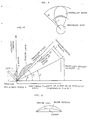
- FIGS. 3 and 4 are diagrams of flow into the front propeller blade section and into the rear turbine blade section, respectively, of the propeller having turbine blades.
- a rotational torque corresponding to a rotation resistance force F ' is given to obtain a thrust T '
- the thrust acts as a rearward resistance force -T T "
- the rotation resistance force acts as a force -F T " to reduce the force.
- the propeller produces a thrust
- the turbine blade obtains energy from a rearward flow from the propeller to serve only as an auxiliary blade to reduce the rotation resistance torque.
- the propeller provided with the turbine blades is a device entirely different from the tandem propeller device.
- the direction of the velocity induced by turbine blades is exactly opposite to the direction of the velocity induced by the propeller.
- the flow induced by the propeller is drawn into the propeller and also follows the direction of rotation of the propeller, but the velocity induced by the turbine blades forces the flow forward and rotates the flow in a direction opposite to the direction of rotation of the propeller.
- the efficiency of the propeller having the turbine blades will be considered.
- ⁇ Pi decreases to ⁇ ' Pi owing to the velocity induced by the turbine blades, consequently improving the efficiency of the front propeller.
- the greater 8i the higher is the efficiency since the direction of the force produced is opposite to that of the propeller.
- a still higher efficiency can be achieved if it is possible to design the turbine blades so that ⁇ Ti of the turbine blades has the following relationship with ⁇ Pi of the propeller blades.
- ⁇ Ti is small, but if the turbine blades are provided in the rear of the propeller, the propeller-induced velocity is accelerated to give an increased ⁇ Ti value, hence an advantage.
- the turbine blades act as solid walls and will produce an effect to block the flow. Especially if positioned in the rearward flow from propeller which is given an accelerated propeller-induced velocity, the turbine blades will presumably produce an enhanced blocking effect.
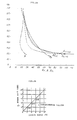
- Table 1 and FIG. 6 show the results of calculations obtained for turbine blades which are 4 in number and 45% of the propeller diameter in diameter, as disposed at varying positions of 0%, 13% and 20%.
- ⁇ no is an increase (%) in efficiency based on the the propeller efficiency.
- Z is in the following range.
- the table and the graph reveal that an efficiency increase of at least 1.8% can be achieved when the number of turbine blades is the number of propeller blades multiplied by an integer (one to three times the latter).
- the table and the graph show that an increase in the turbine blade diameter results in a greater increase in efficiency, whereas an excessive increase in the diameter conversely decreases the efficiency, indicating that efficiency increases of at least 1.8% can be achieved when the turbine blade diameter is in the following range.
- the pitch angle ⁇ m of the rear blades are made to coincide with the direction ⁇ mj of the rear- ward flow from the propeller, the velocity induced by the rear blades becomes zero, and 3' Ti equals ⁇ Ti .
- the pitch angle of the rear blades which are in the form of flat plates satisfies the relation: the rear blades serve as turbine blades.
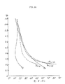
- ⁇ Ti was calculated based on the propeller lifting surface theory and the propeller theory of infinite number of blades, for comparison with the pitch angle ⁇ P of propellers.
- FIGS. 25 to 28 show the results of comparison.
- FIG. 25 shows the results in a uniform flow of a propeller for medium- speed ships
- FIG. 26 shows results in a wake of the same propeller as in FIG. 25
- FIG. 27 shows the results in a wake of other propeller for medium- speed ships
- FIG. 28 shows the results in a wake of a propeller for highspeed ships.
- ⁇ Ti (0), ⁇ Ti (10) and ⁇ Ti (20) mean ⁇ Ti at l of 0%, 10% and 20%, respectively.
- FIGS. 12 to 19 show some embodiments of means for installing the turbine blades 3 in place.
- the turbine blades 3 are provided at their base portions with a ring 3A, which is interposed between a propeller boss 2A and a propeller cap 4 in the rear of the boss, fitted around a propeller shaft 1 and removably fixed in position with bolts 5, 6, 7.
- the propeller boss 2A, ring 3A and cap 4 are fastened together with bolts 5.
- the ring 3A is fastened to the propeller boss 2A with bolts 6, and the cap 4 is fastened to the ring 3A with bolts 7.
- the bolts 5, 6, 7 are inserted through bolt holes 3C formed in the ring 3A axially thereof in a radial arrangement for fastening.
- FIGS. 17 to 19 show embodiments wherein the turbine blades 3 are removably fixed to the outer periphery of the propeller boss 2A with screw fastening means.
- Each turbine blade 3 is provided at its base portion with a flange 13A in the form of a flat plate and having fastening holes 13B. With the flange 13A placed on the outer periphery of the propeller boss 2A, bolts 13C are inserted through the respective fastening holes 13B and driven into female screws formed in the boss.
- FIGS. 14 to 16 show relationships between the ring 3A and the turbine blades 3.
- the ring 3A of FIG. 14 is formed in its outer periphery with axial dovetail grooves 3B in a radial arrangement.
- a dovetail 3D formed at the base portion of the turbine blade 3 is axially fitted into the dovetail groove 3B.
- the dovetail 3D is axially restrained by the propeller boss 2A and cap 4.
- the turbine blades 3 and the ring 3A are integrally formed by casting, welding or the like.
- the turbine blade 3 and the flange 13A are similarly made integrally.
- FIG. 16 shows an embodiment wherein the ring 3A has attaching holes 3E in a radial arrangement, and a projection 3D having a threaded portion is inserted through the hole 3E and fastened with a nut 8.
- the ring 3A of some of the above embodiments can be in the form of a divided ring.
- the turbine blades 3 can be provided with means for adjusting the angle of the blade as attached.
- the turbine blades 3, and the ring 3A or flanges 13A can be made of the same material as the propeller (e.g., copper alloy), or of FRP or like composite material.
- turbine blades are provided in the rear of propeller blades, so that the device produces a greater effect when the velocity induced by the propeller is higher, that is, when the rearward flow from the propeller has a higher velocity and also when the flow following the direction of rotation is greater, hence an improved propeller efficiency.
- the turbine blades are provided at their base portions with flanges or a ring, and the flanges are removably attached to the outer periphery of the propeller boss or the ring is removably provided between the boss and the propeller cap.
- This arrangement makes it possible to use an existing cap as it is for an existing propeller to provide a propelling device having the turbine blades at a low cost.
- the turbine blades can be attached thereto as integral members, or by welding, fitting or fastening with bolts, with considerably great freedom, hence facilitated design and manufacture.
- the present invention can be utilized for ship propelling devices having propeller blades and turbine blades mounted on a propeller shaft.
Landscapes
- Chemical & Material Sciences (AREA)
- Engineering & Computer Science (AREA)
- Combustion & Propulsion (AREA)
- Mechanical Engineering (AREA)
- Ocean & Marine Engineering (AREA)
- Structures Of Non-Positive Displacement Pumps (AREA)
- Hydraulic Turbines (AREA)
- Turbine Rotor Nozzle Sealing (AREA)
- Other Liquid Machine Or Engine Such As Wave Power Use (AREA)
Abstract
Applications Claiming Priority (4)
| Application Number | Priority Date | Filing Date | Title |
|---|---|---|---|
| JP112534/89 | 1989-01-20 | ||
| JP1253489 | 1989-01-20 | ||
| JP197875/89 | 1989-07-29 | ||
| JP1197875A JPH085431B2 (ja) | 1989-01-20 | 1989-07-29 | 舶用推進装置 |
Publications (3)
| Publication Number | Publication Date |
|---|---|
| EP0406451A1 true EP0406451A1 (fr) | 1991-01-09 |
| EP0406451A4 EP0406451A4 (en) | 1991-06-12 |
| EP0406451B1 EP0406451B1 (fr) | 1993-07-28 |
Family
ID=26348161
Family Applications (1)
| Application Number | Title | Priority Date | Filing Date |
|---|---|---|---|
| EP90901906A Expired - Lifetime EP0406451B1 (fr) | 1989-01-20 | 1990-01-19 | Propulseur maritime |
Country Status (5)
| Country | Link |
|---|---|
| EP (1) | EP0406451B1 (fr) |
| JP (1) | JPH085431B2 (fr) |
| KR (1) | KR950003362B1 (fr) |
| DE (1) | DE69002413T2 (fr) |
| WO (1) | WO1990008061A1 (fr) |
Cited By (1)
| Publication number | Priority date | Publication date | Assignee | Title |
|---|---|---|---|---|
| US9328613B2 (en) | 2011-11-18 | 2016-05-03 | Becker Marine Systems Gmbh & Co Kg | Propeller arrangement, in particular for watercraft |
Families Citing this family (10)
| Publication number | Priority date | Publication date | Assignee | Title |
|---|---|---|---|---|
| JP5405872B2 (ja) * | 2009-03-30 | 2014-02-05 | 株式会社三井造船昭島研究所 | 船舶の推進装置とそれを備えた船舶 |
| KR101236748B1 (ko) * | 2010-09-17 | 2013-02-25 | 삼성중공업 주식회사 | 프로펠러 |
| KR101302835B1 (ko) * | 2010-09-20 | 2013-09-02 | 김소연 | 프리휠클러치 터빈을 이용한 선박 추진 시스템 |
| JP6490595B2 (ja) * | 2013-02-08 | 2019-03-27 | 三星重工業株式会社Samsung Heavy Ind.Co.,Ltd. | 船舶の推進装置 |
| CN103939262A (zh) * | 2014-04-14 | 2014-07-23 | 哈尔滨工程大学 | 船用叶轮发电系统 |
| TW201604079A (zh) * | 2014-07-17 | 2016-02-01 | 台灣國際造船股份有限公司 | 螺槳 |
| JP6413909B2 (ja) * | 2015-04-23 | 2018-10-31 | スズキ株式会社 | 船外機 |
| US11713101B2 (en) | 2020-12-04 | 2023-08-01 | Jeffrey L. HATHAWAY | Propeller hubcap |
| JP2024111954A (ja) * | 2023-02-07 | 2024-08-20 | ナカシマプロペラ株式会社 | 船舶用プロペラキャップ |
| CN116353802B (zh) * | 2023-05-25 | 2023-09-08 | 合肥倍豪海洋装备技术有限公司 | 一种进流辅助装置及具有其的螺旋桨 |
Family Cites Families (12)
| Publication number | Priority date | Publication date | Assignee | Title |
|---|---|---|---|---|
| GB191007889A (en) * | 1910-04-01 | 1910-09-29 | Fernand Broussouse | An Improved Propeller. |
| US1386835A (en) * | 1920-01-24 | 1921-08-09 | Birkett Ralph Whitehead | Regenerative counter-propeller for marine vessels |
| DE606119C (de) * | 1933-11-12 | 1934-11-24 | Nicholas Wladimir Akimoff | Einrichtung zur Erhoehung des Wirkungsgrades eines Schraubenpropellers |
| FR820738A (fr) * | 1936-07-24 | 1937-11-17 | Hélice auxiliaire spéciale permettant d'augmenter la vitesse soit des navires soitdes avions, sans augmenter la puissance des machines propulsives | |
| US2199823A (en) * | 1939-05-02 | 1940-05-07 | Kessery Peter | Propeller |
| US2474562A (en) * | 1945-03-30 | 1949-06-28 | Waterval William | Propeller |
| JPS5311490A (en) * | 1976-07-20 | 1978-02-01 | Fumio Henmi | Screw propeller |
| EP0148965B1 (fr) * | 1984-01-14 | 1988-03-16 | Ostermann Metallwerke GmbH & Co | Aménagement d'hélice et de roue guide |
| SE456075B (sv) * | 1984-11-29 | 1988-09-05 | Volvo Penta Ab | Rotorsystem, foretredesvis batpropellersystem |
| JPS6212495A (ja) * | 1985-07-09 | 1987-01-21 | Mitsubishi Heavy Ind Ltd | 舶用プロペラ |
| JPH07121716B2 (ja) * | 1986-07-16 | 1995-12-25 | 大阪商船三井船舶株式会社 | フィン付プロペラボスキャップ |
| JPH05311490A (ja) * | 1991-12-25 | 1993-11-22 | Nikko Kinzoku Kk | 金めっき材の封孔処理方法 |
-
1989
- 1989-07-29 JP JP1197875A patent/JPH085431B2/ja not_active Expired - Lifetime
-
1990
- 1990-01-19 KR KR1019900702091A patent/KR950003362B1/ko not_active Expired - Fee Related
- 1990-01-19 EP EP90901906A patent/EP0406451B1/fr not_active Expired - Lifetime
- 1990-01-19 DE DE90901906T patent/DE69002413T2/de not_active Expired - Fee Related
- 1990-01-19 WO PCT/JP1990/000065 patent/WO1990008061A1/fr not_active Ceased
Cited By (1)
| Publication number | Priority date | Publication date | Assignee | Title |
|---|---|---|---|---|
| US9328613B2 (en) | 2011-11-18 | 2016-05-03 | Becker Marine Systems Gmbh & Co Kg | Propeller arrangement, in particular for watercraft |
Also Published As
| Publication number | Publication date |
|---|---|
| WO1990008061A1 (fr) | 1990-07-26 |
| DE69002413D1 (de) | 1993-09-02 |
| EP0406451A4 (en) | 1991-06-12 |
| KR950003362B1 (ko) | 1995-04-12 |
| DE69002413T2 (de) | 1993-11-25 |
| JPH085431B2 (ja) | 1996-01-24 |
| JPH02279490A (ja) | 1990-11-15 |
| EP0406451B1 (fr) | 1993-07-28 |
| KR910700173A (ko) | 1991-03-14 |
Similar Documents
| Publication | Publication Date | Title |
|---|---|---|
| US6332818B1 (en) | Propulsion system | |
| EP0586511B1 (fr) | Systeme de propulsion a anneaux de poussee | |
| EP0406451B1 (fr) | Propulseur maritime | |
| US5632658A (en) | Tractor podded propulsor for surface ships | |
| US7517263B1 (en) | Advanced blade sections for high speed propellers | |
| CA1136928A (fr) | Helice a echappement par le moyeu | |
| KR100284253B1 (ko) | 토크 컨버터의 스테이터 블레이드 | |
| US6106232A (en) | Propeller structure | |
| US4514146A (en) | Propeller for ship | |
| US4921404A (en) | Propellors for watercraft | |
| US5445105A (en) | Torque balanced postswirl propulsor unit and method for eliminating torque on a submerged body | |
| US4653418A (en) | Rudder with wings and method for manufacture thereof | |
| JP7518942B1 (ja) | 船舶用推進装置及びそれを備えた船舶 | |
| WO1989008580A2 (fr) | Systeme de propulsion a aubes de pre-turbulence asymetriques et a helice torsadee caracterise par une efficacite accrue d'utilisation de l'energie de propulsion | |
| US10710688B2 (en) | Marine propeller | |
| CN212267811U (zh) | 一种水下串联式同转螺旋桨装备 | |
| CN222876259U (zh) | 一种泵喷推进器及航行器 | |
| EP3508415B1 (fr) | Hélice à plaque d'extrémité de type diffuseur | |
| JP3263543B2 (ja) | ハブ渦防止溝付き可変ピッチプロペラ | |
| JPS6216878B2 (fr) | ||
| JPH08282590A (ja) | 舶用プロペラ | |
| US20260042523A1 (en) | Multi-row propeller (mrp) with co-rotating blades | |
| Van Beek | Technology guidelines for efficient design and operation of ship propulsors | |
| JPH04314689A (ja) | 舵 | |
| CN121133966A (zh) | 分段式渐变距螺旋桨桨叶及其设计方法、螺旋桨 |
Legal Events
| Date | Code | Title | Description |
|---|---|---|---|
| PUAI | Public reference made under article 153(3) epc to a published international application that has entered the european phase |
Free format text: ORIGINAL CODE: 0009012 |
|
| 17P | Request for examination filed |
Effective date: 19900906 |
|
| AK | Designated contracting states |
Kind code of ref document: A1 Designated state(s): DE FR GB NL SE |
|
| A4 | Supplementary search report drawn up and despatched |
Effective date: 19910419 |
|
| AK | Designated contracting states |
Kind code of ref document: A4 Designated state(s): DE FR GB NL SE |
|
| 17Q | First examination report despatched |
Effective date: 19920921 |
|
| GRAA | (expected) grant |
Free format text: ORIGINAL CODE: 0009210 |
|
| AK | Designated contracting states |
Kind code of ref document: B1 Designated state(s): DE FR GB NL SE |
|
| ET | Fr: translation filed | ||
| REF | Corresponds to: |
Ref document number: 69002413 Country of ref document: DE Date of ref document: 19930902 |
|
| PLBE | No opposition filed within time limit |
Free format text: ORIGINAL CODE: 0009261 |
|
| STAA | Information on the status of an ep patent application or granted ep patent |
Free format text: STATUS: NO OPPOSITION FILED WITHIN TIME LIMIT |
|
| 26N | No opposition filed | ||
| EAL | Se: european patent in force in sweden |
Ref document number: 90901906.9 |
|
| PGFP | Annual fee paid to national office [announced via postgrant information from national office to epo] |
Ref country code: GB Payment date: 19981208 Year of fee payment: 10 |
|
| PGFP | Annual fee paid to national office [announced via postgrant information from national office to epo] |
Ref country code: SE Payment date: 19981221 Year of fee payment: 10 |
|
| PGFP | Annual fee paid to national office [announced via postgrant information from national office to epo] |
Ref country code: FR Payment date: 19990129 Year of fee payment: 10 |
|
| PGFP | Annual fee paid to national office [announced via postgrant information from national office to epo] |
Ref country code: NL Payment date: 19990131 Year of fee payment: 10 |
|
| PGFP | Annual fee paid to national office [announced via postgrant information from national office to epo] |
Ref country code: DE Payment date: 19990226 Year of fee payment: 10 |
|
| PG25 | Lapsed in a contracting state [announced via postgrant information from national office to epo] |
Ref country code: GB Free format text: LAPSE BECAUSE OF NON-PAYMENT OF DUE FEES Effective date: 20000119 |
|
| PG25 | Lapsed in a contracting state [announced via postgrant information from national office to epo] |
Ref country code: SE Free format text: LAPSE BECAUSE OF NON-PAYMENT OF DUE FEES Effective date: 20000120 |
|
| PG25 | Lapsed in a contracting state [announced via postgrant information from national office to epo] |
Ref country code: NL Free format text: LAPSE BECAUSE OF NON-PAYMENT OF DUE FEES Effective date: 20000801 |
|
| GBPC | Gb: european patent ceased through non-payment of renewal fee |
Effective date: 20000119 |
|
| EUG | Se: european patent has lapsed |
Ref document number: 90901906.9 |
|
| PG25 | Lapsed in a contracting state [announced via postgrant information from national office to epo] |
Ref country code: FR Free format text: LAPSE BECAUSE OF NON-PAYMENT OF DUE FEES Effective date: 20000929 |
|
| NLV4 | Nl: lapsed or anulled due to non-payment of the annual fee |
Effective date: 20000801 |
|
| PG25 | Lapsed in a contracting state [announced via postgrant information from national office to epo] |
Ref country code: DE Free format text: LAPSE BECAUSE OF NON-PAYMENT OF DUE FEES Effective date: 20001101 |
|
| REG | Reference to a national code |
Ref country code: FR Ref legal event code: ST |