EP0406757A2 - Verfahren zur chromatographischen Trennung - Google Patents
Verfahren zur chromatographischen Trennung Download PDFInfo
- Publication number
- EP0406757A2 EP0406757A2 EP90112582A EP90112582A EP0406757A2 EP 0406757 A2 EP0406757 A2 EP 0406757A2 EP 90112582 A EP90112582 A EP 90112582A EP 90112582 A EP90112582 A EP 90112582A EP 0406757 A2 EP0406757 A2 EP 0406757A2
- Authority
- EP
- European Patent Office
- Prior art keywords
- column
- sample
- separation
- detector
- reference compounds
- Prior art date
- Legal status (The legal status is an assumption and is not a legal conclusion. Google has not performed a legal analysis and makes no representation as to the accuracy of the status listed.)
- Granted
Links
Images
Classifications
-
- G—PHYSICS
- G01—MEASURING; TESTING
- G01N—INVESTIGATING OR ANALYSING MATERIALS BY DETERMINING THEIR CHEMICAL OR PHYSICAL PROPERTIES
- G01N30/00—Investigating or analysing materials by separation into components using adsorption, absorption or similar phenomena or using ion-exchange, e.g. chromatography or field flow fractionation
- G01N30/02—Column chromatography
- G01N30/26—Conditioning of the fluid carrier; Flow patterns
- G01N30/38—Flow patterns
- G01N30/46—Flow patterns using more than one column
- G01N30/461—Flow patterns using more than one column with serial coupling of separation columns
-
- G—PHYSICS
- G01—MEASURING; TESTING
- G01N—INVESTIGATING OR ANALYSING MATERIALS BY DETERMINING THEIR CHEMICAL OR PHYSICAL PROPERTIES
- G01N30/00—Investigating or analysing materials by separation into components using adsorption, absorption or similar phenomena or using ion-exchange, e.g. chromatography or field flow fractionation
- G01N30/02—Column chromatography
- G01N30/04—Preparation or injection of sample to be analysed
- G01N30/06—Preparation
-
- G—PHYSICS
- G01—MEASURING; TESTING
- G01N—INVESTIGATING OR ANALYSING MATERIALS BY DETERMINING THEIR CHEMICAL OR PHYSICAL PROPERTIES
- G01N30/00—Investigating or analysing materials by separation into components using adsorption, absorption or similar phenomena or using ion-exchange, e.g. chromatography or field flow fractionation
- G01N30/02—Column chromatography
- G01N30/26—Conditioning of the fluid carrier; Flow patterns
- G01N30/38—Flow patterns
- G01N2030/382—Flow patterns flow switching in a single column
- G01N2030/383—Flow patterns flow switching in a single column by using auxiliary fluid
-
- G—PHYSICS
- G01—MEASURING; TESTING
- G01N—INVESTIGATING OR ANALYSING MATERIALS BY DETERMINING THEIR CHEMICAL OR PHYSICAL PROPERTIES
- G01N30/00—Investigating or analysing materials by separation into components using adsorption, absorption or similar phenomena or using ion-exchange, e.g. chromatography or field flow fractionation
- G01N30/02—Column chromatography
- G01N30/62—Detectors specially adapted therefor
- G01N2030/621—Detectors specially adapted therefor signal-to-noise ratio
- G01N2030/625—Detectors specially adapted therefor signal-to-noise ratio by measuring reference material, e.g. carrier without sample
Definitions
- the present invention relates to a procedure for chromatographic separation whereby the separation between a stationary phase in a column and a mobile phase passed through it is performed in two stages by taking the sample under treatment into a first column for rough separation of the compounds contained in the sample and passing the rough fraction separated from it by said column into another column for a second separation stage.
- Chromatographic separation is based on the partition or sorption occurring between a stationary phase and a mobile phase, which has the effect that the compounds contained in the sample are divided into fractions that move through the column at different speeds.
- the stationary phase may be either liquid or solid, whereas the mobile phase may be either gaseous or liquid.
- the mobile phase is a gas and the stationary phase a viscous liquid.
- the compounds or fractions separated in the column are generally identified on the basis of the retention times, using a detector.
- Chromatographic separation can be implemented as a one-stage process, which, however, has the drawback of a poor separation capability.
- the object under chromatographic separation may be a sample containing tens, hundreds or even thousands of different compounds in very low concentrations, e.g. of the order of a few ppm. Separating the compounds would require very long analysing times, which are not possible in repeated routine analyses.
- Chromatographic analysis of complex samples can be rendered considerably more efficient by performing the separation in two stages in such manner that a first column separates a rough fraction of the sample, whereupon this fraction is cut off and passed to a second column for a definitive separation of the compound under analysis.
- the conditions prevailing in the two columns must be different, and this is achieved e.g. by using different substances as stationary phases in them.
- due to the changes in retention time resulting from the soiling of the column it has been difficult in practice to determine the instant at which the desired fraction should be cut off.
- the object of the present invention is to achieve a two-stage procedure for chromatographic separation based on the use of two successive columns that eliminates the above-mentioned drawback.
- the procedure of the invention is characterized in that one or more reference compounds are introduced into the first column simultaneously with the sample, said reference compounds being so chosen that the retention time of at least one of them is shorter than that of the fraction to be separated from the sample, that the separation taking place in the first column is monitored using a detector, and that, after the detector has detected one or more of the reference compounds, said fraction is transferred to the second column at an instant determined on the basis of the retention times of the detected reference compounds or on the basis of other retention parameters calculated from the retention times.
- the invention eliminates the need for carrying out tests on the sample prior to analysis to determine the instant of cut-off.
- the procedure provides high selectivity, speed and repeatability and permits automatiztion of the routine treatment of similar samples.
- the invention is especially applicable in gas chromatography, where the stationary phases in the columns are mutually differing liquids and the mobile phase in both columns is the same gaseous substance.
- the samples to be analyzed may be liquids, in which case they are vaporized, using an injector, into the mobile phase passed into the first column.
- the reference compounds which may have been mixed in advance with the sample to be injected, are mixed with the mobile phase.
- the reference compounds i.e. retention index standards
- the reference compounds may constitute a homologous series of compounds which are similar to the compounds to be separated from the sample under analysis or to which the latter are otherwise suitably comparable.
- even one reference compound may be sufficient for the realization of the invention, but in practice the best results are achieved by using a series of compounds of which the first two members are obtained from the first separation stage before the fraction to be cut off and one or more members after it.
- the invention also relates to an apparatus for chromatographic separation, comprising two successive columns known in themselves, each of which contains filling material constituting the stationary phase, supply and discharge ducts connected to the first column for passing the mobile phase and the sample under analysis through the column for rough separation of the compounds contained in the sample, and an inter-column connecting duct for transferring the rough fraction separated from the sample by the first column into the second column for the second stage of analysis.
- the apparatus is characterized in that a detector is provided between the columns, allowing the separation taking place in the first column to be so monitored as to permit the transfer of said fraction to be based during analysis on the reference compounds detected by the detector, the reference compounds being introduced into the first column together with the sample.
- the filling materials contained in the columns of the apparatus of the invention may be mutually differing liquids, e.g. polysiloxanes.
- the detector may be e.g. a flame ionization detector, an electron capture detector or a nitrogen-phosphorus detector.
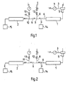
- the separation equipment presented in figs. 1 and 2 comprises two successive columns 1, 2.
- the filling material is a viscous liquid, e.g. methyl polysiloxane, constituting the stationary phase
- the stationary phase in the second one 2 is another liquid, e.g. cyanopropyl polysiloxane.
- a gaseous mobile phase is supplied into the first column 1 via a feed duct 3.
- the feed duct is provided with a pressure gauge 4 and an injector 5 for the evaporation of the sample to be analyzed and the reference compounds or retention index standards into the gas flowing into the column 1.
- a duct 6 Connected to the discharge end of column 1 is a duct 6 which branches off at junction 7 into a discharge duct 8 of column 1 and an interconnecting duct 9 between columns 1 and 2. Via junction 10, the interconnecting duct 9 communicates with a feed duct 11 through which a gaseous mobile phase can be supplied into the second column 2 and, if necessary, also into the discharge duct 8 of column 1 via the interconnecting duct 9.
- the discharge duct 8 and said feed duct 11 connected to the interconnecting duct 9 are provided with valves 12, 13 enabling the ducts to be opened and closed.
- the apparatus is provided with detectors 14, 15, e.g.
- flame ionization detectors one being placed between the columns 1, 2 in conjunction with the duct 6 leading away from column 1 and the other at the discharge end of column 2.
- the strength of the ionization current measured by the detector indicates the material quantity of the fraction eluted from the column.
- the detectors 14, 15 may also be of different types if necessary.
- the object under chromatographic separation treatment using an apparatus as illustrated by the drawing may be e.g. a sample of crude oil in which certain hydrocarbons are to be determined.
- the mobile phase consists of a carrier gas, which may be e.g. hydrogen, nitrogen or helium.
- the sample and the reference compounds which may consist of a homologous series of hydrocarbons of a certain type, are injected at a given instant into the carrier gas, which is supplied as a continuous flow via duct 3 into column 1 and further into the discharge duct 8, the valve 12 in this duct being open. Simultaneously, a continuous flow of carrier gas is supplied via feed duct 11 into the second column 2 and through the interconnecting duct 9 into the discharge duct 8 of column 1. These flows are indicated by arrows in fig. 1.
- the carrier gas flow in feed duct 3 conveys the sample and the reference compounds into the first column 1, where, as a result of the partition occurring between the stationary phase and the carrier gas, the sample is divided into fractions that advance in the column at different speeds. Each fraction remains in the column for a given retention time until it reaches the discharge end.
- detector 14 which is specially aligned so that it will detect the first reference compounds emerging from the column.
- Detector 14 can be so connected to the valves 12, 13 that these will be automatically closed at the instant of cut-off. The flow from the first column 1 will then proceed, as illustrated by the figure, into the second column 2, where the rough fraction will be finally partitioned into separate compounds.
- valves 12, 13 in the discharge duct 8 and feed duct 11 are opened, thus permitting the carrier gas to flow again from the feed duct 11 into the second column 2 and via the interconnecting duct 9 into the discharge duct 8.
- the situation is again as illustrated by fig. 1.
- the fraction which was cut off is partitioned into individual compounds which, after certain retention times, are detected by detector 15.
Landscapes
- Physics & Mathematics (AREA)
- Health & Medical Sciences (AREA)
- Life Sciences & Earth Sciences (AREA)
- Chemical & Material Sciences (AREA)
- Analytical Chemistry (AREA)
- Biochemistry (AREA)
- General Health & Medical Sciences (AREA)
- General Physics & Mathematics (AREA)
- Immunology (AREA)
- Pathology (AREA)
- Treatment Of Liquids With Adsorbents In General (AREA)
- Other Investigation Or Analysis Of Materials By Electrical Means (AREA)
Applications Claiming Priority (2)
| Application Number | Priority Date | Filing Date | Title |
|---|---|---|---|
| FI893243A FI82553C (fi) | 1989-07-04 | 1989-07-04 | Foerfarande och anordning foer kromatografisk separation. |
| FI893243 | 1989-07-04 |
Publications (3)
| Publication Number | Publication Date |
|---|---|
| EP0406757A2 true EP0406757A2 (de) | 1991-01-09 |
| EP0406757A3 EP0406757A3 (en) | 1991-03-13 |
| EP0406757B1 EP0406757B1 (de) | 1995-05-10 |
Family
ID=8528714
Family Applications (1)
| Application Number | Title | Priority Date | Filing Date |
|---|---|---|---|
| EP19900112582 Expired - Lifetime EP0406757B1 (de) | 1989-07-04 | 1990-07-02 | Verfahren zur chromatographischen Trennung |
Country Status (3)
| Country | Link |
|---|---|
| EP (1) | EP0406757B1 (de) |
| DE (1) | DE69019243T2 (de) |
| FI (1) | FI82553C (de) |
Cited By (5)
| Publication number | Priority date | Publication date | Assignee | Title |
|---|---|---|---|---|
| US5350520A (en) * | 1991-04-25 | 1994-09-27 | Shimadzu Corporation | Method for collecting the components of a sample separated by chromatography |
| WO1997038303A1 (en) * | 1996-04-04 | 1997-10-16 | Warner-Lambert Company | Method and system for identification, purification, and quantitation of reaction components |
| DE10064138A1 (de) * | 2000-12-21 | 2002-07-04 | Siemens Ag | Chromatograph |
| DE10214211C1 (de) * | 2002-03-28 | 2003-11-13 | Siemens Ag | Gaschromatograph und Verfahren zur gaschromatographischen Analyse eines Stoffgemischs |
| US8426215B2 (en) | 2002-03-28 | 2013-04-23 | Siemens Aktiengesellschaft | Gas chromatograph and method for analyzing a mixture of substances by gas chromatography |
Families Citing this family (1)
| Publication number | Priority date | Publication date | Assignee | Title |
|---|---|---|---|---|
| DE102014010353B4 (de) * | 2014-07-10 | 2024-09-12 | Sartorius Stedim Biotech Gmbh | Vorrichtung, Verwendung dieser Vorrichtung und Verfahren für die Stofftrennung mit verbesserter Ausnutzung der Kapazität chromatographischer Medien |
Family Cites Families (2)
| Publication number | Priority date | Publication date | Assignee | Title |
|---|---|---|---|---|
| US3717028A (en) * | 1969-06-02 | 1973-02-20 | Foxboro Co | Chromatographic peak selector |
| US4204952A (en) * | 1978-07-07 | 1980-05-27 | Technicon Instruments Corporation | Chromatographic apparatus and method |
-
1989
- 1989-07-04 FI FI893243A patent/FI82553C/fi not_active IP Right Cessation
-
1990
- 1990-07-02 DE DE1990619243 patent/DE69019243T2/de not_active Expired - Fee Related
- 1990-07-02 EP EP19900112582 patent/EP0406757B1/de not_active Expired - Lifetime
Cited By (7)
| Publication number | Priority date | Publication date | Assignee | Title |
|---|---|---|---|---|
| US5350520A (en) * | 1991-04-25 | 1994-09-27 | Shimadzu Corporation | Method for collecting the components of a sample separated by chromatography |
| WO1997038303A1 (en) * | 1996-04-04 | 1997-10-16 | Warner-Lambert Company | Method and system for identification, purification, and quantitation of reaction components |
| DE10064138A1 (de) * | 2000-12-21 | 2002-07-04 | Siemens Ag | Chromatograph |
| DE10064138B4 (de) * | 2000-12-21 | 2004-02-26 | Siemens Ag | Chromatograph |
| US6845650B2 (en) | 2000-12-21 | 2005-01-25 | Siemens Aktiengesellschaft | Gas chromatograph |
| DE10214211C1 (de) * | 2002-03-28 | 2003-11-13 | Siemens Ag | Gaschromatograph und Verfahren zur gaschromatographischen Analyse eines Stoffgemischs |
| US8426215B2 (en) | 2002-03-28 | 2013-04-23 | Siemens Aktiengesellschaft | Gas chromatograph and method for analyzing a mixture of substances by gas chromatography |
Also Published As
| Publication number | Publication date |
|---|---|
| EP0406757A3 (en) | 1991-03-13 |
| EP0406757B1 (de) | 1995-05-10 |
| FI82553C (fi) | 1991-03-11 |
| FI893243A0 (fi) | 1989-07-04 |
| FI82553B (fi) | 1990-11-30 |
| DE69019243D1 (de) | 1995-06-14 |
| DE69019243T2 (de) | 1995-11-09 |
Similar Documents
| Publication | Publication Date | Title |
|---|---|---|
| Mondello et al. | Multidimensional chromatography | |
| Radke et al. | Preparative hydrocarbon group type determination by automated medium pressure liquid chromatography | |
| Hertz et al. | Determination of individual organic compounds in shale oil | |
| May et al. | Liquid chromatographic determination of polycyclic aromatic hydrocarbons in air particulate extracts | |
| Venkatramani et al. | Comprehensive two‐dimensional gas chromatography applied to the analysis of complex mixtures | |
| Deans | Use of heart cutting in gas chromatography: A review | |
| AU2008347646B2 (en) | Method of analyzing a number of hydrocarbons contained in a drilling fluid, and associated device | |
| US4587834A (en) | Method and apparatus for analyzing gases dissolved in a liquid sample | |
| Roeraade | Automated monitoring of organic trace components in water: I. Continuous flow extraction together with on-line capillary gas chromatography | |
| Furtmann | Phthalates in surface water—a method for routine trace level analysis | |
| US6237396B1 (en) | Integrated analysis process and device for hydrocarbon characterization by distillation simulation | |
| US4154583A (en) | Automated temperature programmed preparative chromatography | |
| EP0406757A2 (de) | Verfahren zur chromatographischen Trennung | |
| US3128619A (en) | Method of and apparatus for monitoring for flowing stream content | |
| Widmer et al. | Automated monitor systems for the continuous surveillance of environmental samples | |
| US20090000358A1 (en) | Method of Analysis Using Chromatographic Pre-Separation | |
| Ogan et al. | Analysis of complex samples by coupled-column chromatography | |
| Liem et al. | Analysis of organic micropollutants in the lipid fraction of foodstuffs | |
| EP1408330A4 (de) | Flüssigkeitschromatograph und analysesystem | |
| Vogh et al. | Preparative liquid chromatography for fractionation of petroleum and synthetic crude oils | |
| Krock et al. | Parallel cryogenic trapping multidimensional gas chromatography with directly linked infrared and mass spectral detection | |
| Packham et al. | Column switching for the high-performance liquid chromatographic analysis of polynuclear aromatic hydrocarbons in petroleum products | |
| US3714812A (en) | Electron capture identification apparatus | |
| Roeraade et al. | Preparative gas chromatography with glass capillary columns | |
| Ligon Jr et al. | Some experiences with two-dimensional gas chromatography/mass spectrometry |
Legal Events
| Date | Code | Title | Description |
|---|---|---|---|
| PUAI | Public reference made under article 153(3) epc to a published international application that has entered the european phase |
Free format text: ORIGINAL CODE: 0009012 |
|
| AK | Designated contracting states |
Kind code of ref document: A2 Designated state(s): CH DE FR GB IT LI NL |
|
| PUAL | Search report despatched |
Free format text: ORIGINAL CODE: 0009013 |
|
| AK | Designated contracting states |
Kind code of ref document: A3 Designated state(s): CH DE FR GB IT LI NL |
|
| 17P | Request for examination filed |
Effective date: 19910514 |
|
| 17Q | First examination report despatched |
Effective date: 19930209 |
|
| GRAA | (expected) grant |
Free format text: ORIGINAL CODE: 0009210 |
|
| ITF | It: translation for a ep patent filed | ||
| AK | Designated contracting states |
Kind code of ref document: B1 Designated state(s): CH DE FR GB IT LI NL |
|
| ET | Fr: translation filed | ||
| REF | Corresponds to: |
Ref document number: 69019243 Country of ref document: DE Date of ref document: 19950614 |
|
| PLBE | No opposition filed within time limit |
Free format text: ORIGINAL CODE: 0009261 |
|
| STAA | Information on the status of an ep patent application or granted ep patent |
Free format text: STATUS: NO OPPOSITION FILED WITHIN TIME LIMIT |
|
| 26N | No opposition filed | ||
| PGFP | Annual fee paid to national office [announced via postgrant information from national office to epo] |
Ref country code: CH Payment date: 19980706 Year of fee payment: 9 |
|
| PGFP | Annual fee paid to national office [announced via postgrant information from national office to epo] |
Ref country code: GB Payment date: 19980713 Year of fee payment: 9 |
|
| PGFP | Annual fee paid to national office [announced via postgrant information from national office to epo] |
Ref country code: FR Payment date: 19980721 Year of fee payment: 9 |
|
| PGFP | Annual fee paid to national office [announced via postgrant information from national office to epo] |
Ref country code: NL Payment date: 19980731 Year of fee payment: 9 |
|
| PGFP | Annual fee paid to national office [announced via postgrant information from national office to epo] |
Ref country code: DE Payment date: 19980821 Year of fee payment: 9 |
|
| PG25 | Lapsed in a contracting state [announced via postgrant information from national office to epo] |
Ref country code: GB Free format text: LAPSE BECAUSE OF NON-PAYMENT OF DUE FEES Effective date: 19990702 |
|
| PG25 | Lapsed in a contracting state [announced via postgrant information from national office to epo] |
Ref country code: LI Free format text: LAPSE BECAUSE OF NON-PAYMENT OF DUE FEES Effective date: 19990731 Ref country code: FR Free format text: THE PATENT HAS BEEN ANNULLED BY A DECISION OF A NATIONAL AUTHORITY Effective date: 19990731 Ref country code: CH Free format text: LAPSE BECAUSE OF NON-PAYMENT OF DUE FEES Effective date: 19990731 |
|
| PG25 | Lapsed in a contracting state [announced via postgrant information from national office to epo] |
Ref country code: NL Free format text: LAPSE BECAUSE OF NON-PAYMENT OF DUE FEES Effective date: 20000201 |
|
| GBPC | Gb: european patent ceased through non-payment of renewal fee |
Effective date: 19990702 |
|
| REG | Reference to a national code |
Ref country code: CH Ref legal event code: PL |
|
| NLV4 | Nl: lapsed or anulled due to non-payment of the annual fee |
Effective date: 20000201 |
|
| PG25 | Lapsed in a contracting state [announced via postgrant information from national office to epo] |
Ref country code: DE Free format text: LAPSE BECAUSE OF NON-PAYMENT OF DUE FEES Effective date: 20000503 |
|
| REG | Reference to a national code |
Ref country code: FR Ref legal event code: ST |
|
| PG25 | Lapsed in a contracting state [announced via postgrant information from national office to epo] |
Ref country code: IT Free format text: LAPSE BECAUSE OF NON-PAYMENT OF DUE FEES;WARNING: LAPSES OF ITALIAN PATENTS WITH EFFECTIVE DATE BEFORE 2007 MAY HAVE OCCURRED AT ANY TIME BEFORE 2007. THE CORRECT EFFECTIVE DATE MAY BE DIFFERENT FROM THE ONE RECORDED. Effective date: 20050702 |