EP0406809A2 - Procédé et dispositif pour déterminer l'impédance de boucle à la fréquence de service - Google Patents
Procédé et dispositif pour déterminer l'impédance de boucle à la fréquence de service Download PDFInfo
- Publication number
- EP0406809A2 EP0406809A2 EP19900112697 EP90112697A EP0406809A2 EP 0406809 A2 EP0406809 A2 EP 0406809A2 EP 19900112697 EP19900112697 EP 19900112697 EP 90112697 A EP90112697 A EP 90112697A EP 0406809 A2 EP0406809 A2 EP 0406809A2
- Authority
- EP
- European Patent Office
- Prior art keywords
- current
- filter
- measured
- signal
- voltage
- Prior art date
- Legal status (The legal status is an assumption and is not a legal conclusion. Google has not performed a legal analysis and makes no representation as to the accuracy of the status listed.)
- Granted
Links
Images
Classifications
-
- G—PHYSICS
- G01—MEASURING; TESTING
- G01R—MEASURING ELECTRIC VARIABLES; MEASURING MAGNETIC VARIABLES
- G01R31/00—Arrangements for testing electric properties; Arrangements for locating electric faults; Arrangements for electrical testing characterised by what is being tested not provided for elsewhere
- G01R31/08—Locating faults in cables, transmission lines, or networks
- G01R31/088—Aspects of digital computing
Definitions
- the invention relates to a method and a device or a circuit arrangement for determining the operating frequency loop impedance, which can be used particularly in the case of short-circuit fault location by means of distance protection, in particular when determining the fault impedance of the line concerned, which is necessary for this.
- a fault location method which realizes the traveling wave distance protection principle, the transient processes when the fault occurs being evaluated.
- a disadvantage of this method is that it is based on a total reflection of the wave caused by an error at the measurement location. However, this means that there must be a drastic change in the line impedance at the relay installation location. This method is no longer applicable for a double line.
- the fault location method proposed in DE-A-29 32 929 is based on the superposition principle and the four-pole representation of a homogeneous line in the frequency domain. It feedback on the fault resistance from the other end of the line is eliminated and measurement errors largely avoided.
- the disadvantage is the need for an additional excitation block, which allows the distinction between fault-free and faulty lines in order to obtain pre- and post-error values at all. If aperiodic signal components are present in a current signal, the calculation of the complex pointers of the currents is difficult. The iteration also provided in this known method makes the arithmetic effort for implementation difficult to calculate in advance. From DE-A-36 26 400 a device is known which, by calculating the current-voltage cross-correlation function of the power spectrum, the impedance spectrum and the spectra of current and voltage, deduces the state of the system of the object to be monitored and converts these quantities into one evaluation vector Error signal linked.
- the invention has for its object to provide an inexpensive procedural and equipment solution for determining impedance with regard to the reduction of the project planning and material expenditure in the primary technology.
- the current-frequency loop impedance is to be determined more precisely than with known solutions by means of existing current transformers with a non-linear characteristic curve, and at the same time by means of fault-minimized signals properties, the number of false trips of the distance protection can be reduced.
- the task is solved according to the requirements.
- the voltage value measured in a known manner is corrected with regard to the influence on the neighboring system; with this corrected value, a current signal is generated using a first-order digital filter, which represents an estimated value for the primary current on the line.
- This current is converted by means of a non-linear current transformer model into a current signal which represents the estimated value of the measurable secondary current of the main current transformer.
- the model error signal which is determined by the difference between the measured and estimated secondary current, can be used to readjust the parameters of the digital filter by means of a PE (prediction error) estimator known per se. The readjustment is carried out in such a way that the model error becomes minimal. From the parameters of the digital filter, the operating frequency pointer of the transfer function corresponding to this coefficient set and this filter current is used as the impedance value.
- indexes X (k + n) sample of the size x at time (k + n) * T A x ⁇ estimate of the size x.
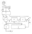
- the drawing shows a preferred embodiment of the circuit arrangement according to the invention, the signal flow being indicated.
- the circuit arrangement comprises a zero-current converter 1 of the neighboring system, a voltage converter 2 of the loop to be measured, a current converter 3 of the loop to be measured and a measured value recording system 4 which receives the output signals of the zero-current converter 1 , the voltage converter 2 and the current converter 3 and outputs signals u (k) and i 0 (k) which corresponds to the detected voltage or the detected current and are supplied to a device 5 for voltage signal correction, which in turn emits an output signal which corresponds to the voltage value corrected for the influence of induction from the neighboring system u corresponds.
- This signal is converted in a filter device 6 downstream of the device 5 for voltage signal correction, which is a filter of the 1st order and preferably a digital filter and represents the line model, into a signal corresponding to the current î 1 (k) , which is an estimate of the primary current represents on the line.
- a current signal is generated therefrom which represents the estimated value î 2 (k) of the measurable secondary current of the main current transformer, which is compared in a difference former with the estimated secondary current i 2 (k) , the corresponding signal of which is supplied by the measured value recording system 4 becomes.
- the model error signal corresponding to the difference ê (k) between the measured and estimated secondary current is fed to a PE estimating device 9 , which alternates with the device 5 for voltage signal correction, the filter device 6 and a device 8 for the transformer mation of the filter coefficients is connected, with the output signals, the parameters of the filter device 6 are adjusted so that the model error is minimal.
- the circuit arrangement is designed such that the operating frequency pointer of the transfer function corresponding to this filter coefficient set and this filter shape is determined from the parameters of the filter device 6 , the reciprocal value of which corresponds to the loop impedance.
- This circuit arrangement can be implemented in terms of device technology both in hard-wired form, for example in the form of application-specific hardware, and, for example, in the form of a programmable controller.
- the circuit arrangement is implemented as a digital microprocessor system which performs the functions of the device 5 for voltage signal correction, the filter device 6 , the current transformer model 7 , the device 8 for transforming the filter coefficients and the PE estimating device 9 and, if appropriate, also the measured value acquisition system 4 takes over and carries out the impedance value determination.
- the circuit arrangement can also have an output or output device and / or a display device with which result values e.g. can be output, printed out and / or displayed.
- the measuring method is based on an application of estimation theory.
- the main advantage of the presented method compared to known solutions is the adaptive behavior of the models used in the method in relation to the states of the protected object while the method is insensitive to aperiodic Shares in the current signal. This is achieved by combining a line model based on a transmission function description with an evaluation rule of the estimated filter parameters based on a priori information about the measured signals.
- the described model of the process to be identified includes the model of the inductive coupling of the neighboring system by means 5 for voltage signal correction, - The model of the line itself in the form of the filter device 6 representing a general filter and - The current transformer model 7 for emulating the inductive main current transformer.
- the voltage signal correction in the device 5 is based on the fact that only the zero currents of a three-phase line running parallel to the conductor loop to be measured cause an influence.
- the voltage measured across the conductor loop is regarded as the sum of the voltage drop caused by the loop current and the voltage induced by the neighboring system (application of the superposition principle).
- the voltage signal unaffected by induction processes from the neighboring system is obtained by subtracting the induction voltage u ind from the measured voltage u.
- This filter implements any transmission behavior that has not been previously defined. In contrast to previously known methods, this also guarantees an exact measurement in the fault-free case of the conductor loop to be measured.
- the line model is thus just as adaptable to the short-circuit case as to a capacitive load case.
- the output signal of the line model which represents an estimate of the non-measurable primary current i 1 flowing in the conductor loop to be measured, is preferably a digital nonlinear current transformer model in order to obtain the estimated value of the measurable secondary current i 2 of the current transformer installed in the conductor loop to be measured.
- This converter model can e.g. B.
- î 2 (k) î 1 (k) + î H (k)
- the magnetizing current of the main transducer i H can be determined relatively easily using the Runge-Kutta method:
- the output signal 1 2 (k) of the converter model can now be made available to the PE estimator of the secondary current to be measured:
- the reciprocal of this pointer represents the 50 Hz value of the loop impedance.
- the transformation of the filter coefficients in the device 8 provides the measured values R and X.
Landscapes
- Physics & Mathematics (AREA)
- Engineering & Computer Science (AREA)
- Mathematical Physics (AREA)
- Theoretical Computer Science (AREA)
- General Physics & Mathematics (AREA)
- Emergency Protection Circuit Devices (AREA)
Applications Claiming Priority (2)
| Application Number | Priority Date | Filing Date | Title |
|---|---|---|---|
| DD330322 | 1989-07-03 | ||
| DD33032289A DD301206A7 (de) | 1989-07-03 | 1989-07-03 | Verfahren zur ermittlung der betriebsfrequenten schleifenimpedanz |
Publications (3)
| Publication Number | Publication Date |
|---|---|
| EP0406809A2 true EP0406809A2 (fr) | 1991-01-09 |
| EP0406809A3 EP0406809A3 (en) | 1992-01-08 |
| EP0406809B1 EP0406809B1 (fr) | 1993-12-15 |
Family
ID=5610513
Family Applications (1)
| Application Number | Title | Priority Date | Filing Date |
|---|---|---|---|
| EP90112697A Expired - Lifetime EP0406809B1 (fr) | 1989-07-03 | 1990-07-03 | Procédé et dispositif pour déterminer l'impédance de boucle à la fréquence de service |
Country Status (3)
| Country | Link |
|---|---|
| EP (1) | EP0406809B1 (fr) |
| DD (1) | DD301206A7 (fr) |
| DE (1) | DE59003850D1 (fr) |
Cited By (2)
| Publication number | Priority date | Publication date | Assignee | Title |
|---|---|---|---|---|
| WO2000031849A1 (fr) * | 1998-11-20 | 2000-06-02 | Siemens Aktiengesellschaft | Procede permettant de produire un signal d'erreur signalant un court-circuit |
| CN110441649A (zh) * | 2019-06-27 | 2019-11-12 | 国网福建省电力有限公司福州供电公司 | 一种架空-电缆混合线路故障快速定位装及定位方法 |
Family Cites Families (3)
| Publication number | Priority date | Publication date | Assignee | Title |
|---|---|---|---|---|
| SE433405B (sv) * | 1982-09-14 | 1984-05-21 | Asea Ab | Forfarande och anordning for lokalisering av ett felstelle pa en trefasig kraftledning |
| DE3626400A1 (de) * | 1986-08-04 | 1988-02-11 | Siemens Ag | Anordnung zur schnellerkennung von kurzschluessen |
| DE3709532A1 (de) * | 1987-03-23 | 1988-10-06 | Siemens Ag | Verfahren zur pruefung von anordnungen |
-
1989
- 1989-07-03 DD DD33032289A patent/DD301206A7/de unknown
-
1990
- 1990-07-03 EP EP90112697A patent/EP0406809B1/fr not_active Expired - Lifetime
- 1990-07-03 DE DE90112697T patent/DE59003850D1/de not_active Expired - Fee Related
Cited By (4)
| Publication number | Priority date | Publication date | Assignee | Title |
|---|---|---|---|---|
| WO2000031849A1 (fr) * | 1998-11-20 | 2000-06-02 | Siemens Aktiengesellschaft | Procede permettant de produire un signal d'erreur signalant un court-circuit |
| US6633166B1 (en) | 1998-11-20 | 2003-10-14 | Siemens Aktiensellscraft | Method for generating an error signal identifying a short circuit |
| CN110441649A (zh) * | 2019-06-27 | 2019-11-12 | 国网福建省电力有限公司福州供电公司 | 一种架空-电缆混合线路故障快速定位装及定位方法 |
| CN110441649B (zh) * | 2019-06-27 | 2021-10-08 | 国网福建省电力有限公司福州供电公司 | 一种架空-电缆混合线路故障快速定位装及定位方法 |
Also Published As
| Publication number | Publication date |
|---|---|
| DD301206A7 (de) | 1992-10-22 |
| EP0406809B1 (fr) | 1993-12-15 |
| DE59003850D1 (de) | 1994-01-27 |
| EP0406809A3 (en) | 1992-01-08 |
Similar Documents
| Publication | Publication Date | Title |
|---|---|---|
| EP3351949B1 (fr) | Procédé et dispositif de détermination de l'emplacement d'un défaut à la terre par rapport à une conduite d'un réseau d'alimentation électrique triphasé ayant un point en étoile non mis à la terre | |
| DE69711251T2 (de) | Elektronisches Relais | |
| DE3687451T2 (de) | Methode zur ortung eines fehlers bei einer energieleitung und vorrichtung zur durchfuehrung der methode. | |
| EP0106790B1 (fr) | Méthode et appareil pour localiser un défaut d'une ligne triphasée à courant | |
| EP3193420A1 (fr) | Procede, dispositif et systeme destines a localiser un defaut sur une ligne d'un reseau d'alimentation electrique | |
| DE19746719C1 (de) | Verfahren zum Gewinnen eines eine Pendelung in einem elektrischen Energieversorgungsnetz anzeigenden Signals | |
| EP1664804B1 (fr) | Procede et dispositif de mesure de tension | |
| DE102012107021B4 (de) | Vorrichtung und Verfahren zur Messung eines Wechselstroms | |
| EP3598151A1 (fr) | Procédé et dispositif de détermination de la répartition d'une résistance totale d'isolement et de la répartition d'une capacité totale de dérivation du réseau dans un système d'alimentation en courant isolé terre | |
| EP2204660A1 (fr) | Dispositif et procédé de détermination de déchargements partiels sur un composant électrique | |
| DE4434749A1 (de) | Verfahren zur Bestimmung der elektrischen Parameter von Asynchronmotoren | |
| DE102021101693B3 (de) | Verfahren zur Messimpuls-Fehlererkennung und Verfahren zur Bestimmung einer Netzableitkapazität für die Anwendung in einem Verfahren zur Isolationsüberwachung in einem ungeerdeten Stromversorgungssystem | |
| DE102019127579B3 (de) | Überwachungsvorrichtung für Ableitströme | |
| WO2001006265A2 (fr) | Procede de determination de l'amplitude et de l'angle de phase d'un signal de mesure correspondant au courant ou a la tension d'un reseau electrique de distribution d'energie | |
| DE202012012649U1 (de) | Vorrichtung zur Messung eines Wechselstroms | |
| EP0406809B1 (fr) | Procédé et dispositif pour déterminer l'impédance de boucle à la fréquence de service | |
| DE69522307T2 (de) | Schutzrelaissystem mit differenzfilter und summierfilter | |
| DE3426490C2 (de) | Schaltungsanordnung zur Fehlerortung bei einer Fernsprechleitung | |
| DE3812433A1 (de) | Verfahren zur bestimmung des fehlerortes auf einer elektrischen leitung | |
| EP0707247A1 (fr) | Dispositif d'analyse, en particulier pour les eaux usées | |
| DE19928192B4 (de) | Verfahren zur Rekonstruktion eines Stromes | |
| EP0069790A1 (fr) | Procédé et dispositif pour localiser des pertes à la terre de réseaux aériens pour courant à haute tension | |
| DE19734722C2 (de) | Verfahren und Vorrichtung zur Verbesserung der Stromqualität eines überlagerten Netzes | |
| DE19849020A1 (de) | Vorrichtung und Verfahren zum Orten von Störstellen in elektrischen Verteilnetzen | |
| EP0532521B1 (fr) | Procede de controle de dispositifs |
Legal Events
| Date | Code | Title | Description |
|---|---|---|---|
| PUAI | Public reference made under article 153(3) epc to a published international application that has entered the european phase |
Free format text: ORIGINAL CODE: 0009012 |
|
| AK | Designated contracting states |
Kind code of ref document: A2 Designated state(s): DE FR GB SE |
|
| RAP1 | Party data changed (applicant data changed or rights of an application transferred) |
Owner name: VE KOMBINAT VERBUNDNETZE ENERGIE ZFT-INSTITUT FUER |
|
| PUAL | Search report despatched |
Free format text: ORIGINAL CODE: 0009013 |
|
| AK | Designated contracting states |
Kind code of ref document: A3 Designated state(s): DE FR GB SE |
|
| 17P | Request for examination filed |
Effective date: 19920527 |
|
| RAP1 | Party data changed (applicant data changed or rights of an application transferred) |
Owner name: VEREINIGTE ENERGIEWERKE AKTIENGESELLSCHAFT INSTITU |
|
| 17Q | First examination report despatched |
Effective date: 19921022 |
|
| RAP3 | Party data changed (applicant data changed or rights of an application transferred) |
Owner name: VEAG VEREINIGTE ENERGIEWERKE AG |
|
| GRAA | (expected) grant |
Free format text: ORIGINAL CODE: 0009210 |
|
| AK | Designated contracting states |
Kind code of ref document: B1 Designated state(s): DE FR GB SE |
|
| PG25 | Lapsed in a contracting state [announced via postgrant information from national office to epo] |
Ref country code: GB Effective date: 19931215 Ref country code: FR Effective date: 19931215 |
|
| REF | Corresponds to: |
Ref document number: 59003850 Country of ref document: DE Date of ref document: 19940127 |
|
| EN | Fr: translation not filed | ||
| GBV | Gb: ep patent (uk) treated as always having been void in accordance with gb section 77(7)/1977 [no translation filed] |
Effective date: 19931215 |
|
| PLBE | No opposition filed within time limit |
Free format text: ORIGINAL CODE: 0009261 |
|
| STAA | Information on the status of an ep patent application or granted ep patent |
Free format text: STATUS: NO OPPOSITION FILED WITHIN TIME LIMIT |
|
| 26N | No opposition filed | ||
| EAL | Se: european patent in force in sweden |
Ref document number: 90112697.9 |
|
| PGFP | Annual fee paid to national office [announced via postgrant information from national office to epo] |
Ref country code: DE Payment date: 19970903 Year of fee payment: 8 |
|
| PGFP | Annual fee paid to national office [announced via postgrant information from national office to epo] |
Ref country code: SE Payment date: 19980615 Year of fee payment: 9 |
|
| PG25 | Lapsed in a contracting state [announced via postgrant information from national office to epo] |
Ref country code: DE Free format text: LAPSE BECAUSE OF NON-PAYMENT OF DUE FEES Effective date: 19990501 |
|
| PG25 | Lapsed in a contracting state [announced via postgrant information from national office to epo] |
Ref country code: SE Free format text: THE PATENT HAS BEEN ANNULLED BY A DECISION OF A NATIONAL AUTHORITY Effective date: 19990704 |
|
| EUG | Se: european patent has lapsed |
Ref document number: 90112697.9 |