EP0406845B1 - Druckknopf-Lichtkreissystem - Google Patents
Druckknopf-Lichtkreissystem Download PDFInfo
- Publication number
- EP0406845B1 EP0406845B1 EP90112797A EP90112797A EP0406845B1 EP 0406845 B1 EP0406845 B1 EP 0406845B1 EP 90112797 A EP90112797 A EP 90112797A EP 90112797 A EP90112797 A EP 90112797A EP 0406845 B1 EP0406845 B1 EP 0406845B1
- Authority
- EP
- European Patent Office
- Prior art keywords
- light
- leds
- touch button
- base
- button system
- Prior art date
- Legal status (The legal status is an assumption and is not a legal conclusion. Google has not performed a legal analysis and makes no representation as to the accuracy of the status listed.)
- Expired - Lifetime
Links
- 239000007787 solid Substances 0.000 claims description 11
- 239000000463 material Substances 0.000 claims description 9
- 238000007373 indentation Methods 0.000 claims description 5
- 230000013011 mating Effects 0.000 claims description 5
- 238000009792 diffusion process Methods 0.000 claims description 3
- 230000006835 compression Effects 0.000 claims description 2
- 238000007906 compression Methods 0.000 claims description 2
- 230000003213 activating effect Effects 0.000 claims 1
- 125000001475 halogen functional group Chemical group 0.000 description 4
- 230000000007 visual effect Effects 0.000 description 4
- 229910000831 Steel Inorganic materials 0.000 description 3
- 238000005286 illumination Methods 0.000 description 3
- 239000010959 steel Substances 0.000 description 3
- JAYCNKDKIKZTAF-UHFFFAOYSA-N 1-chloro-2-(2-chlorophenyl)benzene Chemical compound ClC1=CC=CC=C1C1=CC=CC=C1Cl JAYCNKDKIKZTAF-UHFFFAOYSA-N 0.000 description 2
- 101100084627 Neurospora crassa (strain ATCC 24698 / 74-OR23-1A / CBS 708.71 / DSM 1257 / FGSC 987) pcb-4 gene Proteins 0.000 description 2
- 239000004020 conductor Substances 0.000 description 2
- 239000004606 Fillers/Extenders Substances 0.000 description 1
- 239000004418 Lexan Substances 0.000 description 1
- 230000000712 assembly Effects 0.000 description 1
- 238000000429 assembly Methods 0.000 description 1
- 230000004888 barrier function Effects 0.000 description 1
- 230000005465 channeling Effects 0.000 description 1
- 239000003086 colorant Substances 0.000 description 1
- 238000004891 communication Methods 0.000 description 1
- 238000010276 construction Methods 0.000 description 1
- 230000001276 controlling effect Effects 0.000 description 1
- 238000010586 diagram Methods 0.000 description 1
- 230000000694 effects Effects 0.000 description 1
- 238000005516 engineering process Methods 0.000 description 1
- 239000002184 metal Substances 0.000 description 1
- 238000012544 monitoring process Methods 0.000 description 1
- 230000003287 optical effect Effects 0.000 description 1
- 230000000149 penetrating effect Effects 0.000 description 1
- 230000002093 peripheral effect Effects 0.000 description 1
- 239000004417 polycarbonate Substances 0.000 description 1
- 229920000515 polycarbonate Polymers 0.000 description 1
- 230000001105 regulatory effect Effects 0.000 description 1
- 230000011664 signaling Effects 0.000 description 1
- 239000012780 transparent material Substances 0.000 description 1
Images
Classifications
-
- B—PERFORMING OPERATIONS; TRANSPORTING
- B66—HOISTING; LIFTING; HAULING
- B66B—ELEVATORS; ESCALATORS OR MOVING WALKWAYS
- B66B1/00—Control systems of elevators in general
- B66B1/34—Details, e.g. call counting devices, data transmission from car to control system, devices giving information to the control system
- B66B1/46—Adaptations of switches or switchgear
- B66B1/461—Adaptations of switches or switchgear characterised by their shape or profile
- B66B1/463—Touch sensitive input devices
-
- B—PERFORMING OPERATIONS; TRANSPORTING
- B66—HOISTING; LIFTING; HAULING
- B66B—ELEVATORS; ESCALATORS OR MOVING WALKWAYS
- B66B3/00—Applications of devices for indicating or signalling operating conditions of elevators
- B66B3/002—Indicators
- B66B3/004—Mechanical devices that can be illuminated
-
- H—ELECTRICITY
- H03—ELECTRONIC CIRCUITRY
- H03K—PULSE TECHNIQUE
- H03K17/00—Electronic switching or gating, i.e. not by contact-making and –breaking
- H03K17/18—Modifications for indicating state of switch
-
- H—ELECTRICITY
- H03—ELECTRONIC CIRCUITRY
- H03K—PULSE TECHNIQUE
- H03K17/00—Electronic switching or gating, i.e. not by contact-making and –breaking
- H03K17/94—Electronic switching or gating, i.e. not by contact-making and –breaking characterised by the way in which the control signals are generated
- H03K17/96—Touch switches
- H03K17/962—Capacitive touch switches
-
- G—PHYSICS
- G09—EDUCATION; CRYPTOGRAPHY; DISPLAY; ADVERTISING; SEALS
- G09F—DISPLAYING; ADVERTISING; SIGNS; LABELS OR NAME-PLATES; SEALS
- G09F13/00—Illuminated signs; Luminous advertising
- G09F13/20—Illuminated signs; Luminous advertising with luminescent surfaces or parts
- G09F13/22—Illuminated signs; Luminous advertising with luminescent surfaces or parts electroluminescent
-
- H—ELECTRICITY
- H01—ELECTRIC ELEMENTS
- H01H—ELECTRIC SWITCHES; RELAYS; SELECTORS; EMERGENCY PROTECTIVE DEVICES
- H01H2219/00—Legends
- H01H2219/054—Optical elements
- H01H2219/062—Light conductor
- H01H2219/0622—Light conductor only an illuminated ring around keys
-
- H—ELECTRICITY
- H03—ELECTRONIC CIRCUITRY
- H03K—PULSE TECHNIQUE
- H03K2217/00—Indexing scheme related to electronic switching or gating, i.e. not by contact-making or -breaking covered by H03K17/00
- H03K2217/94—Indexing scheme related to electronic switching or gating, i.e. not by contact-making or -breaking covered by H03K17/00 characterised by the way in which the control signal is generated
- H03K2217/96—Touch switches
- H03K2217/9607—Capacitive touch switches
- H03K2217/960785—Capacitive touch switches with illumination
-
- Y—GENERAL TAGGING OF NEW TECHNOLOGICAL DEVELOPMENTS; GENERAL TAGGING OF CROSS-SECTIONAL TECHNOLOGIES SPANNING OVER SEVERAL SECTIONS OF THE IPC; TECHNICAL SUBJECTS COVERED BY FORMER USPC CROSS-REFERENCE ART COLLECTIONS [XRACs] AND DIGESTS
- Y10—TECHNICAL SUBJECTS COVERED BY FORMER USPC
- Y10S—TECHNICAL SUBJECTS COVERED BY FORMER USPC CROSS-REFERENCE ART COLLECTIONS [XRACs] AND DIGESTS
- Y10S362/00—Illumination
- Y10S362/80—Light emitting diode
Definitions
- the present invention relates to touch buttons typically used to activate or deactivate some electrical or electronic function, such as signaling, when touched typically by a human operator touching or “pushing" on the button with a finger.
- the invention more particularly relates to a light ring containing a circular array of light emitting diodes (LEDs) for a solid state touch button system operated, for example, by capacitive sensing, and even more particularly to such a button which can be used in many different applications, including particularly a touch or push button for elevator car calling or control, with the light ring providing visual feedback to the operator that the button has been actuated.
- LEDs light emitting diodes
- buttons an encircling light ring, which is illuminated when the button has been actuated as a visual feedback to the operator.
- rings received light from incandescent bulbs.
- the '739 patent discloses an elevator control switch and position indicator assembly for mounting in a panel comprising a piezoelectric element and a control circuit connected to the element for generating an elevator control pulse in response to an output signal from the element.
- a circular push button assembly is arranged such that, when the push button is operated, a force is applied to the piezoelectric element, and the push button assembly is restrained so that it can only deflect the element a predetermined distance sufficient to produce an output signal.
- the assembly further comprises an integral indicator device for providing an indication to the operator that an elevator control signal has been generated. The device is indicated as being configurable to provide an indication of the position of an elevator car.
- the light from a single, centrally located, long-life LED (44) with multiple elements for increased luminous intensity, in place of the short lived bulb of the prior art, is fed through a lens guide (16), forming a generally annular cross-section lens for guiding light to an externally disposed lens ring (42), to form a halo effect.
- the ring is illustrated as being integrally formed with the lens guide, which can be made of optical grade polycarbonate.
- the surfaces facing the LED are not described, they are illustrated as appearing primarily, if not completely, laterally extended, with the nature of the facing surface not being clearly illustrated, with two laterally extended, parallel lines appearing in the drawing (Fig. 1).
- a separately actuated LED (74) without any light pipe is positioned above the other LED and its lens guide to separately illuminate a centrally located, translucent graphic disk (76) positioned directly over it (in place of the operator button) to serve as an elevator car position indicator.
- the '037 patent discloses the use of separated, independent LEDs in a controller apparatus for detecting lamp failures in an elevator system, an application not at all analogous to a touch or push button with a surrounding light ring.
- the '992 patent discloses the use of "light emitting means” (14) to illuminate indication marks on an elevator panel. Exactly what the “light emitting means” is, is not clear. But again, regardless of the nature of the "light emitting means,” there is no suggestion of, inter alia , an annular, circular array of a multiple number of LEDs above a circular surface feeding the light rays from the multiple LEDs to the button surrounding light ring, producing a highly diffused, bright halo, with a relatively even luminosity, much less any of the many other innovative features of the present invention.
- the light ring of the invention preferably includes an annular, transparent or translucent, light pipe section having an open center at its end which faces the exterior (such as, for example, the hall or car, as the case may be, when used in an elevator system), and a restricted, basal end, which is hidden in the wall behind the button touch surface.
- a plurality of LEDs are mounted inside the basal end of the light ring in an annular, circular array, and, preferably, an alternating series of saw-toothed or grooved annulus of light dispersing, internal, triangular interfaces or light receiving surfaces is disposed between the LEDs and the ring end of the rim.
- Various, other innovative features preferably are included to, inter alia , insure the proper alignment and keying of the sub-elements which make up the light ring, including a printed circuit board (PCB) base, which carries the LEDs and some of its associated circuitry, and the molded light transmitting body of the light ring.
- PCB printed circuit board
- the invention may be practiced in a wide variety of applications, including but certainly not restricted to elevator car call or control buttons, utilizing known technology, in the light of the teachings of the invention, which are discussed in detail hereafter.
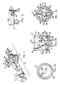
- Figure 1 is an exploded, perspective view of an exemplary solid state push button assembly, including the button, light ring, printed circuit (PC) board and holder for attaching the PC board to the push button elements and the overall button assembly to a face plate or panel, with the PC board carrying the electrical components which form the exemplary electronics and circuitry of the present invention.
- the touch button elements of Figure 1 are basically symmetrical about their longitudinal center-line, except for the PC board and its associated holder.
- Figures 2A, 2B & 2C are top, side/cross-sectional and bottom views, respectively, of the light ring element of the button assembly of Figure 1 .
- Figure 3 is a partial, side view showing the bottom portion of the light ring element of Figs. 2A-2C .
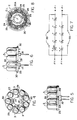
- Figure 4 is a top view of the LED base element of the light ring element of Figs. 2A-2C ; while Figure 5 is a side view thereof, and Figure 6 is a further side view with the base rotated ninety (90°) from its position in Fig. 5 .
- Figure 7 is a schematic diagram of the LED circuitry of the light ring element of Figs. 2A-2C .
- Figure 8 is a cross-sectional view of the light ring element of Figs. 2A-2C (taken along section line 8-8 of Figure 2B ) looking up into the triangularly topped cavities in the light ring element in which the LEDs are positioned, and which cause the light emanating from the LEDs to be disbursed up into and through the transparent material of the upper portion of the light ring element to be transmitted out of the surrounding ring portion of the element to be viewed by, for example, the button pusher.
- the exemplary "solid state button” (SSB) assembly 10 of the present invention preferably includes a non-moving, capacitive sensing button surface 1 , that can be used, for example, as a call button in the car operating panel (COP) and/or hall fixtures of an elevator system.
- the SSB is capable of capacitively sensing a human touch, preferably providing both visual feed back (illumination) to the button pusher, as well as communication to the operational control of the elevator system via a remote station (RS; not illustrated) interface that the button has been actuated, so that the system accordingly can react.
- RS remote station
- the exemplary button system of Figure 1 includes the non-moving button element 1 fitted within a light ring element 2 , in which ring is carried a circular array of light emitting diodes (LEDs) 3 at its bottom, there being preferably at least five (5) LEDs, with nine being used in the illustrated, exemplary, currently preferred embodiment.
- LEDs light emitting diodes
- a printed circuit board 4 into which the light ring element 2 is pin inserted, is carried on the back side of the button elements 1 , 2 , and is held to the button elements by a bracket 5 and a rear bolt 6 having a bolt head 6B .
- the bolt head 6B extends past the bottoms of all of the other button elements of the button assembly 10 .
- An interconnecting bolt or stem 7 has a front, threaded, male end 7A , which is screwed into the back side of the button surface 1 , and a rear, threaded, male end 7B , which is screwed into the front end 6A of the rear bolt 6 with a lock washer 7C .
- the interconnecting bolt 7 extends through a center, generally circular opening 20 (which can be seen in Figures 2A-2C and 4 & 8 ) in the light ring element 2 and through an opening in the PC board 4 , while the head 6B of the rear bolt 6 fits into a notch in a "U" shaped rear strap 8 , which is part of the bracket holder 5 .
- the bolt or stem 7 has a series of longitudinally extended, flat, side surfaces 7C , forming a hexagonal cross-section for the stem which mates with a like configured, interior surface 21 , which forms the lower part of the central opening 20 .
- the intermediate elements of the button assembly 10 When assembled, the intermediate elements of the button assembly 10 are held in compression between the button surface 1 and the head 6B of the bolt 6 .
- the flat surface interfacing of the stem 7 and the interior opening 21 fixes and keys them together about their common, longitudinal axis, thus preventing the light ring 2 from being rotatable or movable around the stem about their common, longitudinal axis.
- the bracket 5 includes a series of peripherally spaced, lateral extensions or arms 9 , through which threaded screw pins 9B are placed for fastening the button assembly 10 to a face plate or panel by means of like threaded female orifices in the face plate or panel.
- the only elements of the button assembly 10 which are seen by the user is the non-moving, circular button surface 1 surrounded by the translucent ring 2A , which is illuminated with relatively bright, relatively evenly diffused light originally emanating from the internally contained LEDs when the button is actuated.
- the top ring portion 2A could be illuminated by its associated circuitry when the button is in its "off" condition.
- the printed circuit board 4 carries on it the electronic components and associated circuitry which perform the monitoring functions of the button.
- the circuitry/push button assembly preferably is an autobalancing or a constant pressure arrangement.
- the substantially cylindrical body of the light ring 2 includes a top ring portion 2A of light emitting material encircling the button surface element 1 , an upper portion 27 of light transmitting material, and a bottom portion, which is (but need not be) of light transmitting material.
- the bottom portion includes a base 23 carrying an array of LEDs 3 .
- the illumination of the light ring 2 is controlled by the button surface 1 through appropriate circuitry, as discussed in some detail in the co-pending application (OT-791).
- the source of the illumination is comprised, for example, of two strings of LEDs 3 located at the bottom of the light ring 2 and are fed preferably by dedicated current regulators through pin connectors J2 and J3 (note Figs. 2C & 7 ), which pin connectors are inserted into connector openings in the printed circuit board (PCB) 4 .
- the current through each string of LEDs 3 is regulated to, for example, thirty (30mA) milliamps, by appropriately controlling the voltage.
- Compensating resistors 35 can be included with the LEDs 3 , if so desired.
- an exemplary nine LEDs 3 are included, preferably equally spaced about the periphery of the bottom base area 22 of the light ring 2 , forming an annular array.
- the connecting pins for the nine ( 1-9 ) LEDs 3 all fall on the periphery of a circle about the longitudinal center line ( C.L. ; note Fig. 2B ) of the light ring 2 , except for the initial, first ( 1 ) and second ( 2 ) LEDs in each string (note schematic of Fig. 7 ) and the sixth ( 6 ) one, which is oppositely positioned to the positions of the first and second ones.
- the two pin connections or leads for each of these three LEDs are preferably positioned in a line parallel to a lateral line LL bisecting the base 23 .
- the base 23 which is substantially circular in its lateral extent, is a printed circuit board (PCB), which includes printed, conductive lead lines interconnecting the LEDs 3 in two parallel strings, along with two associated, compensating resistors 35 , if such is needed or desired, in accordance with the circuitry schematic of Figure 7 .
- PCB printed circuit board
- each LED 3 "looks up" into the center of an triangulated chamber 24 , with each individual chamber preferably being made up of three, inclined, triangular surfaces sharing a common apex 25 , which is located at the outermost point of the central triangular surface and is at the outermost periphery of the inside of the light ring 2 .
- Each of the three triangular surfaces of each chamber 24 includes a series of molded-in straight edges 26 , each of which extends across its respective surface leading up to their common apex in a stepped fashion.
- Each of these chambers 24 serves as the light receiving surfaces for its respective LED 3 , channeling the light in a highly diffused manner into and through the light-pipe-like, solid interior of the upper portion 27 of the light ring 2 leading to the encircling, top, light ring portion 2A , through which the light from the light ring 2 is seen by the button user.
- the series of straight edges or steps function as Fresnel-like grooving on the underside of the upper interior of the light ring 2 .
- the interior side 20A (note Figs. 8 & 2B ) of the surface 20 preferably is frosted, which frosted surface 20A , as can be seen in Figure 8 , is convex and terminates in the base side of the central one of the three triangulated surfaces forming the chambers 24 .
- one of the triangulated surfaces of each chamber 24 is positioned between the other two, sharing common sides with them, while the saw-toothed grooves or Fresnel-like edges 26 are disposed parallel to their respective bases of the triangulated surfaces.
- the upper, central, conical, circular area or centrally facing, exterior surface 20 is sloped at an angle of, for example, sixty (60°) degrees, that is, at an angle of thirty (30°) degrees to the center line C.L. . This is done in order to provide diffusion reflection in the solid, light transmitting interior 27 and thus minimize the loss of any light from the solid interior of the ring 2 into the open, center area defined by the interior, center side of the conical surface 20 , where the light effectively would be lost or wasted.
- This overall arrangement produces a relatively uniform intensity of light at and about the outer, encircling ring 2A , although the light ultimately seen there originated in fact from the relatively discrete, spaced, light sources generated by the nine, peripherally spaced LEDs 3 .
- the light ring 2 and in particular the upper, solid, light “pipe” portion 27 , can be made of a single, integral, molded piece of transparent "LEXAN TM " (940 AR), with the exception of the PCB base 23 and its associated electrical components.
- the molded body In order to properly align the molded body portion of the light ring 2 and the PCB base 23 with its LEDs 3 ), the molded body includes two, longitudinally extended, peripherally positioned but off-set, integrally molded pins or projections 28 , which mate into circular indentations or cut-outs 29 similarly located in the periphery of the base, keying the two sub-elements together.
- the base 23 also includes two, opposed, radially directed projections 30 , which fit into openings 31 (note Fig. 3 ) in flexible longitudinal extensions 32 in the molded body portion of the ring 2 .
- the pins 28 (and accordingly the indentations 29 ) preferably are offset, rather than being directly opposed, by being peripherally spaced from one another by an angle of, for example, one hundred and sixty (160°) degrees ( vis-a-vis 180°). This insures that there is only one way or one mating alignment in which the base 23 can be positioned with respect to the ring body.
- the extensions 32 flex out, allowing the radially directed projections to snap into the openings 31 , latching the two sub-elements together.
- the extensions 32 are merely pulled laterally out, allowing the base 23 and its electrical components to be removed down and out away from the ring body.
- the pin connectors J2 & J3 When assembled, the pin connectors J2 & J3 are inserted into their respective mating openings in the PCB 4 to be connected into the circuit for the button assembly 10 .
- Peripheral, longitudinally extended portions or bosses 34 are included to support the bottom of the ring 2 on the PCB 4 and prevent any rocking of the ring 2 about the bottom surfaces of the headers of the pin connectors J2 & J3 .
- resistors 35 could be included on and carried by the PCB base 23 , along with their associated LEDs 3 (note Figs. 5 & 6 ). These resistors 35 are connected into the circuitry of the base, as shown in the schematic of Figure 7 , by appropriately placed, printed circuit board lead lines on the base.
- a rectangular "label" area 33 (note Fig. 3 ) can be provided on the lower side of the ring molded body to identify or serialize the ring 2 , if so desired.
- exemplary dimensions for the light ring 2 are outlined below: Part Dimension Diameter of top ring portion 2A 1" Longitudinal length of body of light ring 2 1.1" Longitudinal length of cylindrical, interior part of upper part 27 0.25" Longitudinal length of inclined, conical part 20 0.5" Longitudinal length of hex. area 21 1.5" Lateral width of hex. area 21 0.25"
- the exemplary solid state button assembly 10 described in detail above is designed to be applied in a hall fixture and/or car operating panel (COP) of an elevator, although, of course, many other uses and applications are possible.
- COP car operating panel
- the hall fixture application allows for two button assemblies (not illustrated), a beeper or key switch assembly and an RS-4 type board to fit into a commercially available masonry box.
- the masonry box (not illustrated) used should provide a shallow wall depth for the entire assembly.
- a shallow wall depth [for example, sixty-five (65 mm) millimeters] avoids penetrating the hoist-way fire barrier in common commercial construction.
- the face plates can be made of, for example, die cast metal and be available in various finishes. Also one, two or three (1, 2 or 3) position combinations of buttons or key switches can be used.
- a tamper proof fastener (not illustrated) preferably is used to fasten the face plate to the masonry box.
- the COP application allows for multiple buttons to be mounted in a panel and connected to a Remote Serial Extender Board (not illustrated).
- the face plate should be connected to the masonry box with, for example, an insulated flat braided conductor (not illustrated), having, for example, a maximum length of eighteen (18 cm.) centimeters.
- the masonry box should be bonded to building steel through wiring conduit or a flat braided conductor to the closest building steel.
- a chassis ground is applied on the button from the face plate (hall fixture) or return panel (COP).
- face plate hall fixture
- COP return panel
- the only product variations needed for the exemplary applications are the two colors of light rings, namely, red and green, and the application of the button to a hall fixture and a COP.
- the exemplary unit described above is a relatively low cost, easily replaceable device, taking, for example, five (5) minutes to replace.
Landscapes
- Engineering & Computer Science (AREA)
- Automation & Control Theory (AREA)
- Mechanical Engineering (AREA)
- Computer Networks & Wireless Communication (AREA)
- Elevator Control (AREA)
- Push-Button Switches (AREA)
- Switch Cases, Indication, And Locking (AREA)
- Illuminated Signs And Luminous Advertising (AREA)
Claims (20)
- Beleuchtetes Berührungsknopfsystem zum Aktivieren oder Deaktivieren einer elektrisch gesteuerten Funktion, mit einem die Berührungsknopfoberfläche umgebenden Lichtring (2A) zum Beleuchten des Knopfes (1), das aufweist:
ein Lichtringelement mit einem obersten Ringbereich (2A) aus lichtdurchlässigem Material, einem oberen Bereich (27) mit einem Vollinneren aus lichtdurchlässigem Material und einem unteren Bereich;
ein Knopfelement (1), das in dem Lichtringelement (2) angeordnet ist und von seinem lichtdurchlässigen obersten Ringbereich umgeben ist;
und eine Gruppierung umfangsmäßig beabstandeter, an dem unteren Bereich (23) angeordneter, lichtemittierender Dioden (LEDs) (3), wobei der obere Bereich aus lichtdurchlässigem Material das Licht, das von einem Knopf-Bediener gesehen werden soll und den "Ein"/"Aus"-Zustand des Knopfes (1) anzeigt, von den LEDs (3) zu dem obersten Ringbereich (2) überträgt. - Berührungsknopfsystem nach Anspruch 1, bei dem der obere Bereich aus lichtdurchlässigem Material eine lichtaufnehmende Unterseite (24) besitzt, die der Gruppierung aus LEDs (3) zugewandt ist, die, wenn die LEDs eingeschaltet sind, einiges von dem Licht der LEDs aufnimmt und die eine Reihe beabstandeter, Fresnel-artiger Kanten (26) aufweist.
- Berührungsknopfsystem nach Anspruch 1, bei dem der obere Bereich aus lichtdurchlässigem Material eine lichtaufnehmende Unterseite (24) besitzt, die der Gruppierung aus LEDs (3) zugewandt ist, die einiges von dem Licht der LEDs aufnimmt und die eine Reihe einzelner, auf dem Umfang der Unterseite beabstandeter Kammern (24) aufweist, wobei jede der LEDs unter einer der Kammern angeordnet ist und ihr Licht, wenn sie angeschaltet ist, auf die Kammer (24) überträgt.
- Berührungsknopfsystem nach Anspruch 3, bei dem jede der Kammern (24) eine geneigte Fläche aufweist, die ihrer jeweiligen LED (3) zugewandt ist und von dieser Licht in das Vollinnere des oberen Bereichs aufnimmt.
- Berührungsknopfsystem nach Anspruch 4, bei dem jede der geneigten Flächen eine Reihe beabstandeter, Fresnel-artiger Kanten (26) besitzt, die ihrer jeweiligen LED zugewandt sind.
- Berührungsknopfsystem nach Anspruch 3, bei dem jede der Kammern (24) einen Satz aus wenigstens zwei lichtaufnehmenden, dreieckigen Oberflächen aufweist, die nach unten in Richtung auf ihre jeweilige LED geneigt sind.
- Berührungsknopfsystem nach Anspruch 6, bei dem jede Kammer aufweist:
wenigstens drei geneigte, dreieckige Oberflächen, die jeweils an einer gemeinsamen Spitze (25) teilhaben, die in Richtung auf die äußere Außenseite des Lichtrings angeordnet ist. - Berührungsknopfsystem nach Anspruch 7, bei dem jede der geneigten, dreieckigen Oberflächen eine Reihe von beabstandeten, Fresnel-artigen Kanten aufweist, die ihrer jeweiligen LED zugewandt sind und parallel zur Grundlinie ihrer jeweiligen dreieckigen Oberfläche angeordnet sind.
- Berührungsknopfsystem nach Anspruch 8, bei dem eine der drei dreieckigen Oberflächen zwischen den anderen beiden angeordnet ist, und sich mit diesen gemeinsame Seitenlinien teilt; und bei dem außerdem eine nach außen gekrümmte, konvexe, geneigte Oberfläche enthalten ist, die in der Grundlinie dieser einen der drei dreieckigen Oberflächen endet.
- Berührungsknopfsystem nach Anspruch 9, bei dem die konvexe, geneigte Oberfläche mattiert ist.
- Berührungsknopfsystem nach einem der Ansprüche 1 bis 10, bei dem der obere Bereich eine äußere, zur Mitte gerichtete Seite mit einer Mittellinienachse (C.L) besitzt und an dieser äußeren, zur Mitte gerichteten Seite (20) eine konische Oberfläche aufweist, die einen Winkel mit ihrer Mittellinienachse bildet, was für die Lichtstrahlen, die sich in seinem lichtdurchlässigen Vollmaterial fortbewegen diffuse Reflexion wirkt, wenn die von den LEDs (3) in das Vollmaterial eingetretenen Lichtstrahlen zu dem obersten Ringbereich übertragen werden, wobei das Licht, das von den LEDs in das offene Innere des oberen Bereichs geht, wenigstens reduziert wird.
- Berührungsknopfsystem nach Anspruch 11, bei dem der Winkel in der Größenordnung von dreißig (30°) Grad liegt.
- Berührungsknopfsystem nach einem der Ansprüche 1 bis 12, bei dem die LEDs (3) auf einer gedruckten Schaltplatten (PCB)-Basis (23) getragen sind, die an dem unteren Bereich des Lichtringelements befestigt ist und von diesem getragen ist.
- Berührungsknopfsystem nach Anspruch 13, bei dem das Lichtringelement (2) in Längsrichtung von dem obersten Ringbereich zu dem untersten Bereich ausgedehnt ist und an seiner nach außen gewandten Außenseite eine im wesentlichen zylindrische Gestalt hat, wobei an seinem unterem Bereich von der PCB-Basis (23) getragen in einer ringförmigen Rundgruppierung mindestens fünf umfangsmäßig beabstandete LEDs (3) angeordnet sind.
- Berührungsknopfsystem nach Anspruch 13 oder 14, bei dem der untere Bereich an seinem äußeren Umfang mindestens zwei flexible, untere Verlängerungen (28), jede mit einer Einrastöffnung, aufweist; und bei dem die Basis (23) eine im wesentlichen runde Form hat sowie zwei radial gerichtete Vorsprünge (30) aufweist, die in die Einrastöffnungen (31) passen, wobei die Basis (23) am unteren Bereich durch Zusammenwirken der Vorsprünge (30) mit den Einrastöffnungen (31) verrastet ist.
- Berührungsknopfsystem nach einem der Ansprüche 13 bis 15, bei dem der untere Bereich an seinem äußeren Umfang mindestens zwei umfangmäßig versetzte, sich in Längsrichtung erstreckende Verriegelungsstifte (J2, J3) aufweist; und bei dem die Basis (23) an ihrem Umfang zwei nach der äußeren Gestalt der Verriegelungsstifte (J2, J3) geformte, Verbindungseintiefungen aufweist, in denen die Verriegelungsstifte (J2, J3) angeordnet sind.
- Berührungsknopfsystem nach einem der Ansprüche 13 bis 16, bei dem die LEDs mittels auf der PCB-Basis (23) gedruckter Leiterbahnen in mindestens zwei parallelen Strängen elektrisch miteinander verbunden sind.
- Berührungsknopfsystem nach Anspruch 17, bei dem die Basis (23) im wesentlichen rund ist und jede der LEDs (3) zwei elektrische Leitungen aufweist, wobei mindestens eine LED ihre beiden Leiter parallel einer, die Basis halbierenden, sich lateral erstreckenden Linie angeordnet hat, und wobei mindestens vier LEDs ihre jeweiligen beiden Leiter entlang dem Umfang eines gemeinsamen Kreises um den Mittelpunkt der Basis angeordnet haben.
- Berührungsknopfsystem nach Anspruch 1, bei dem das Ringelement (2) eine mittig angeordnete Durchgangsöffnung aufweist, von der mindestens ein Teil eine Reihe flacher, langgestreckter, lagedefinierender Flächen besitzt;
und das Knopfelement (1) eine Unterseite besitzt, die in Richtung zu dem unteren Bereich des Lichtringelements weist und an der Unterseite einen mittig angeordneten, mit einem Gewinde versehenen Teil besitzt;
und bei dem außerdem eine Basis (23) enthalten ist, welche die an dem unteren Bereich befestigten LEDs trägt und eine mittig angeordnete Durchgangsöffnung besitzt, wobei die mittig angeordneten Öffnungen und die mit Gewinde versehenen Bereiche in einer geraden Linie ausgerichtet sind;
und bei dem außerdem ein langgestrecktes Stielbolzenelement (7) mit einem hinter der Basis angeordneten Kopfende und einem Gewindeende enthalten ist; das mit dem mittig angeordneten, mit einem Gewinde versehenen Teil zusammenpaßt, wobei das Bolzenelement (7) die Basis (23), das Lichtringelement (2) und das Knopfelement (1) zusammenhalt. - Berührungsknopfsystem nach Anspruch 19, bei dem außerdem enthalten sind:
eine gedruckte Schaltplatte (PCB) (23), die elektrische Bauteile aufweist, die den LEDs (3) elektrisch zugeordnet sind und mittels Stiftverbindungen, die der Unterseite des Basis zugeordnet sind, an die Basis angeschlossen sind, wobei die PCB eine mittig angeordnete Durchgangsöffnung besitzt, die mit den mittig angeordneten Öffnungen in dem Lichtringelement und der Basis (23) ausgerichtet ist; und
ein Befestigungshalter, welcher der PCB zugeordnet ist; wobei sich das Bolzenelement (7) durch alle mittig angeordneten Öffnungen erstreckt und mit seinem Kopf hinter der PCB sowie hinter mindestens einem Teil des Befestigungshalters angeordnet ist, wobei das Bolzenelement das Lichtringelement, die PCB und den Befestigungshalter unter Druck zwischen der Knopfoberfläche und dem Kopf zusammenhält.
Applications Claiming Priority (2)
| Application Number | Priority Date | Filing Date | Title |
|---|---|---|---|
| US07/376,079 US5039832A (en) | 1989-07-05 | 1989-07-05 | Touch button light ring system |
| US376079 | 1989-07-05 |
Publications (3)
| Publication Number | Publication Date |
|---|---|
| EP0406845A2 EP0406845A2 (de) | 1991-01-09 |
| EP0406845A3 EP0406845A3 (en) | 1991-07-03 |
| EP0406845B1 true EP0406845B1 (de) | 1994-01-12 |
Family
ID=23483631
Family Applications (1)
| Application Number | Title | Priority Date | Filing Date |
|---|---|---|---|
| EP90112797A Expired - Lifetime EP0406845B1 (de) | 1989-07-05 | 1990-07-04 | Druckknopf-Lichtkreissystem |
Country Status (8)
| Country | Link |
|---|---|
| US (1) | US5039832A (de) |
| EP (1) | EP0406845B1 (de) |
| JP (1) | JP2815986B2 (de) |
| AU (1) | AU630717B2 (de) |
| DE (1) | DE69005927T2 (de) |
| FI (1) | FI96249C (de) |
| HK (1) | HK90794A (de) |
| ZA (1) | ZA903591B (de) |
Cited By (5)
| Publication number | Priority date | Publication date | Assignee | Title |
|---|---|---|---|---|
| US8443007B1 (en) | 2006-10-24 | 2013-05-14 | Slacker, Inc. | Systems and devices for personalized rendering of digital media content |
| US8712563B2 (en) | 2006-10-24 | 2014-04-29 | Slacker, Inc. | Method and apparatus for interactive distribution of digital content |
| US10275463B2 (en) | 2013-03-15 | 2019-04-30 | Slacker, Inc. | System and method for scoring and ranking digital content based on activity of network users |
| US10313754B2 (en) | 2007-03-08 | 2019-06-04 | Slacker, Inc | System and method for personalizing playback content through interaction with a playback device |
| US10657168B2 (en) | 2006-10-24 | 2020-05-19 | Slacker, Inc. | Methods and systems for personalized rendering of digital media content |
Families Citing this family (58)
| Publication number | Priority date | Publication date | Assignee | Title |
|---|---|---|---|---|
| US5661793A (en) * | 1990-02-15 | 1997-08-26 | Hitachi Telecom Technologies, Ltd. | Key unit |
| EP0442467B1 (de) * | 1990-02-15 | 1997-10-29 | Hitachi Telecom Technologies, Ltd. | Installationsstruktur für Handelspult |
| US5160200A (en) * | 1991-03-06 | 1992-11-03 | R & D Molded Products, Inc. | Wedge-base LED bulb housing |
| CA2063889C (en) * | 1991-07-26 | 1998-04-28 | Edward Berdich | Surface mounted indicating element for elevators |
| JPH0750379B2 (ja) * | 1991-11-11 | 1995-05-31 | 帝菱産業株式会社 | 発光体ユニットにおける発光単体装着方法および発光単体装着構造 |
| FR2697484B1 (fr) * | 1992-11-02 | 1995-01-20 | Valeo Vision | Elément modulaire pour la réalisation de feux de signalisation de véhicules automobiles. |
| US5295050A (en) * | 1992-11-23 | 1994-03-15 | Eaton Corporation | Display system |
| US5288957A (en) * | 1992-12-28 | 1994-02-22 | Otis Elevator Company | Illuminated touch button switch |
| US5308943A (en) * | 1992-12-28 | 1994-05-03 | Otis Elevator Company | Convertible hybrid touch button switch |
| KR940019586A (ko) * | 1993-02-04 | 1994-09-14 | 휴고 라이히무트, 한스 블뢰흐레 | 엘리베이터용 표시소자 |
| US5697689A (en) * | 1993-08-09 | 1997-12-16 | General Automotive Specialty Co., Inc. | Rotary switch indicator including horseshoe light guide |
| ATE177065T1 (de) * | 1993-08-12 | 1999-03-15 | Inventio Ag | Druckknopfelement |
| US5400228A (en) * | 1994-07-12 | 1995-03-21 | Kao; Pin-Chi | Full color illuminating unit |
| US5899557A (en) * | 1994-08-11 | 1999-05-04 | Mcdermott; Kevin | Multi-source lighting device |
| TW347616B (en) | 1995-03-31 | 1998-12-11 | Qualcomm Inc | Method and apparatus for performing fast power control in a mobile communication system a method and apparatus for controlling transmission power in a mobile communication system is disclosed. |
| US5820246A (en) * | 1996-02-08 | 1998-10-13 | Eaton Corporation | Display system having electroluminescent devices |
| FI98965C (fi) * | 1996-04-23 | 1997-09-10 | Kone Oy | Järjestely hissin painonapissa |
| JPH10188094A (ja) * | 1996-12-24 | 1998-07-21 | Kouha:Kk | 自動販売機等の押ボタン |
| TW402856B (en) * | 1996-12-26 | 2000-08-21 | Palite Corp | LED illuminator |
| US5929788A (en) * | 1997-12-30 | 1999-07-27 | Star Headlight & Lantern Co. | Warning beacon |
| DE19857837A1 (de) * | 1998-12-15 | 2000-06-21 | Mannesmann Vdo Ag | Bedienvorrichtung |
| US6454424B1 (en) * | 2000-10-11 | 2002-09-24 | General Electric Company | RV light lens |
| US6590174B2 (en) | 2001-03-30 | 2003-07-08 | Visteon Global Technologies, Inc. | Switch assembly having diffused illumination |
| DE10218294B4 (de) | 2002-04-24 | 2021-12-09 | BSH Hausgeräte GmbH | Vorrichtung zur Steuerung von elektrisch ansteuerbaren Geräten, insbesondere von elektrischen Haushaltsgeräten |
| TWI237282B (en) * | 2003-01-07 | 2005-08-01 | Pentax Corp | Push button device having an illuminator |
| US20050264529A1 (en) * | 2004-04-30 | 2005-12-01 | Avidyne Corporation | Display method and system with select lighting to denote button action |
| GB0422927D0 (en) * | 2004-10-15 | 2004-11-17 | Gamesman Ltd | Push button assembly |
| EP1817783B1 (de) * | 2004-10-15 | 2010-11-17 | Gamesman Limited | Druckknopfanordnung |
| TWI253662B (en) * | 2004-12-29 | 2006-04-21 | Tatung Co Ltd | A pressed key structure with light source |
| TWI283421B (en) * | 2005-03-11 | 2007-07-01 | Coretronic Corp | Backlight button assembly |
| DE102005014770A1 (de) * | 2005-03-31 | 2006-10-05 | Siemens Ag Österreich | Formteil als optischer Lichtleiter |
| DE102005015814B4 (de) * | 2005-04-06 | 2007-06-28 | Siemens Ag Österreich | Formteil als optischer Lichtleiter |
| US7588359B2 (en) * | 2005-09-26 | 2009-09-15 | Osram Sylvania Inc. | LED lamp with direct optical coupling in axial arrangement |
| JP4708220B2 (ja) | 2006-03-03 | 2011-06-22 | 富士通株式会社 | 照明装置及びこれを用いた撮像装置 |
| FR2899164B1 (fr) * | 2006-03-31 | 2009-04-17 | Valeo Vision Sa | Dispositif d'eclairage pour allume-cigare ou prise electrique multi-fonction |
| DE102006023593A1 (de) * | 2006-05-19 | 2007-11-22 | Valeo Schalter Und Sensoren Gmbh | Lichtleitelement |
| DE102006025141A1 (de) * | 2006-05-30 | 2007-12-06 | BSH Bosch und Siemens Hausgeräte GmbH | Verfahren zur Herstellung eines Blendenteils für ein Bedienpanel mit berührungsempfindlichen Sensortasten, insbesondere für ein Haushaltsgerät |
| US20080029349A1 (en) * | 2006-08-07 | 2008-02-07 | Poppell James W | Non-personal-contact electric switch apparatus |
| FR2906947B1 (fr) * | 2006-10-05 | 2008-12-05 | Brandt Ind Sas | Dispositif a touche sensitive par effet capacitif retro eclaire et clavier de commande comprenant un tel dispositif. |
| TW201003469A (en) * | 2008-07-01 | 2010-01-16 | Avermedia Information Inc | Cursor control device |
| US8178802B2 (en) | 2008-07-31 | 2012-05-15 | Electrolux Home Products, Inc. | Unitized appliance control panel assembly and components of the assembly |
| US8187024B2 (en) * | 2009-03-23 | 2012-05-29 | Tyco Electronics Corporation | Connector assembly with a light indicative of a connector status |
| WO2011090844A1 (en) * | 2010-01-21 | 2011-07-28 | Illinois Tool Works Inc. | Light ring for appliance control adjustable for console thickness |
| JP5263193B2 (ja) * | 2010-02-04 | 2013-08-14 | オムロン株式会社 | 近接センサ |
| JP5560061B2 (ja) * | 2010-02-24 | 2014-07-23 | 京楽産業.株式会社 | 遊技機用ボタンスイッチ装置及び遊技機用ボタンスイッチ装置を備えた遊技機 |
| US20110205179A1 (en) * | 2010-02-25 | 2011-08-25 | Research In Motion Limited | Three-dimensional illuminated area for optical navigation |
| US8937598B2 (en) * | 2010-02-25 | 2015-01-20 | Blackberry Limited | Illuminated optical navigation module |
| US8982063B2 (en) | 2010-02-25 | 2015-03-17 | Blackberry Limited | Optical naviagation module having a metallic illumination ring |
| US8866708B2 (en) | 2011-01-21 | 2014-10-21 | Peter Sui Lun Fong | Light emitting diode switch device and array |
| US10073537B2 (en) * | 2012-03-12 | 2018-09-11 | Samsung Electronics Co., Ltd. | User interface device and electronic apparatus having the same |
| JP6374327B2 (ja) * | 2015-01-29 | 2018-08-15 | 富士フイルム株式会社 | バルーン制御装置用リモートコントローラ及び内視鏡システム |
| US10405414B2 (en) * | 2015-02-02 | 2019-09-03 | Amico Clinical Solutions Corporation | Lamp bypass switch |
| EP3258460B1 (de) * | 2016-06-15 | 2019-02-20 | Henkel AG & Co. KGaA | Platte für eine elektronische vorrichtung und verfahren |
| KR200497482Y1 (ko) * | 2017-11-10 | 2023-11-22 | 사우스코 인코포레이티드 | 레버 압축 래치 |
| US10914430B2 (en) * | 2017-12-31 | 2021-02-09 | Google Llc | Smart-home device light rings with lens spacing for uniform output |
| CN109411273A (zh) * | 2018-11-14 | 2019-03-01 | 珠海格力电器股份有限公司 | 一种按键组件及具有其的遥控装置 |
| US10754075B1 (en) * | 2019-04-09 | 2020-08-25 | Signify Holding B.V. | Light assembly having a ring-shaped lightguide with a plurality of light incident portions |
| US11248769B2 (en) | 2019-04-10 | 2022-02-15 | Peter Sui Lun Fong | Optic for touch-sensitive light emitting diode switch |
Family Cites Families (12)
| Publication number | Priority date | Publication date | Assignee | Title |
|---|---|---|---|---|
| US1823319A (en) * | 1927-10-11 | 1931-09-15 | Dickinson William Noble | Responsive signal system |
| US3267926A (en) * | 1964-07-27 | 1966-08-23 | Otis Elevator Co | Illuminated push button switch assembly |
| US4163883A (en) * | 1977-12-30 | 1979-08-07 | Texas Instruments Incorporated | Keyboard with illuminated keys |
| US4179594A (en) * | 1978-09-12 | 1979-12-18 | Westinghouse Electric Corp. | Illuminated pushbutton assembly |
| JPS5722581Y2 (de) * | 1979-08-21 | 1982-05-17 | ||
| JPS5991615A (ja) * | 1982-11-18 | 1984-05-26 | 株式会社サン電業社 | 照光式押ボタンスイツチ |
| US4758701A (en) * | 1984-03-14 | 1988-07-19 | Allen-Bradley Company | Indicator light assembly for control panel |
| US4583151A (en) * | 1984-10-22 | 1986-04-15 | Allen-Bradley Company | Illuminated display |
| US4650037A (en) * | 1985-06-05 | 1987-03-17 | Westinghouse Electric Corp. | Elevator system |
| JPS6260786A (ja) * | 1985-09-09 | 1987-03-17 | 三菱電機株式会社 | エレベ−タの操作盤 |
| FR2600266B1 (fr) * | 1986-06-19 | 1990-08-24 | Lorraine Carbone | Procede de fabrication d'une membrane minerale poreuse sur un support mineral |
| US4805739A (en) * | 1988-01-14 | 1989-02-21 | U.S. Elevator Corporation | Elevator control switch and position indicator assembly |
-
1989
- 1989-07-05 US US07/376,079 patent/US5039832A/en not_active Expired - Fee Related
-
1990
- 1990-05-10 ZA ZA903591A patent/ZA903591B/xx unknown
- 1990-06-05 FI FI902796A patent/FI96249C/fi not_active IP Right Cessation
- 1990-07-02 AU AU58675/90A patent/AU630717B2/en not_active Ceased
- 1990-07-04 EP EP90112797A patent/EP0406845B1/de not_active Expired - Lifetime
- 1990-07-04 DE DE90112797T patent/DE69005927T2/de not_active Expired - Fee Related
- 1990-07-05 JP JP2178497A patent/JP2815986B2/ja not_active Expired - Lifetime
-
1994
- 1994-09-01 HK HK90794A patent/HK90794A/en not_active IP Right Cessation
Cited By (5)
| Publication number | Priority date | Publication date | Assignee | Title |
|---|---|---|---|---|
| US8443007B1 (en) | 2006-10-24 | 2013-05-14 | Slacker, Inc. | Systems and devices for personalized rendering of digital media content |
| US8712563B2 (en) | 2006-10-24 | 2014-04-29 | Slacker, Inc. | Method and apparatus for interactive distribution of digital content |
| US10657168B2 (en) | 2006-10-24 | 2020-05-19 | Slacker, Inc. | Methods and systems for personalized rendering of digital media content |
| US10313754B2 (en) | 2007-03-08 | 2019-06-04 | Slacker, Inc | System and method for personalizing playback content through interaction with a playback device |
| US10275463B2 (en) | 2013-03-15 | 2019-04-30 | Slacker, Inc. | System and method for scoring and ranking digital content based on activity of network users |
Also Published As
| Publication number | Publication date |
|---|---|
| FI96249B (fi) | 1996-02-15 |
| DE69005927D1 (de) | 1994-02-24 |
| EP0406845A3 (en) | 1991-07-03 |
| AU5867590A (en) | 1991-01-10 |
| AU630717B2 (en) | 1992-11-05 |
| US5039832A (en) | 1991-08-13 |
| FI96249C (fi) | 1996-05-27 |
| DE69005927T2 (de) | 1994-05-05 |
| JP2815986B2 (ja) | 1998-10-27 |
| FI902796A0 (fi) | 1990-06-05 |
| JPH03179624A (ja) | 1991-08-05 |
| EP0406845A2 (de) | 1991-01-09 |
| HK90794A (en) | 1994-09-09 |
| ZA903591B (en) | 1991-03-27 |
Similar Documents
| Publication | Publication Date | Title |
|---|---|---|
| EP0406845B1 (de) | Druckknopf-Lichtkreissystem | |
| US6729738B2 (en) | Illumination devices for watches and other instruments | |
| US9958138B2 (en) | Vehicle trim assembly | |
| US10847985B2 (en) | Flashlight with longitudinal cooling fins | |
| US4912334A (en) | Infrared aircraft beacon light | |
| GB2293692A (en) | Illuminated switch assemblies | |
| AU2002348303A1 (en) | Touch sensor with integrated decoration | |
| JPH06290669A (ja) | エレベータで使用するための発光ダイオードで照明した押しボタンスイッチ | |
| HK1002738B (en) | Push button switch illuminated by led for use with elevators | |
| US20040189604A1 (en) | Computer mouse with ornamental light source | |
| US9112505B2 (en) | Illuminated capacitive switch button | |
| CN113874656B (zh) | 用于触敏发光二极管开关的光学装置 | |
| US6508562B1 (en) | Instrument cluster reflector | |
| AU2013100505A4 (en) | Power Outlet Socket Sensor Switch | |
| US10204492B2 (en) | Visual signalling device for control and/or display unit | |
| KR20240035182A (ko) | 무드등이 구비된 엘이디 시계 | |
| KR200365961Y1 (ko) | 4색 엘이디를 이용한 인테리어 시계 | |
| CN223246752U (zh) | 一种可探测距离变化的灯具 | |
| CN212965912U (zh) | 电子设备 | |
| KR102278394B1 (ko) | 자동차용 실내 조명기구 | |
| JPH054180Y2 (de) | ||
| CN111245418B (zh) | 开关模组 | |
| GB2322009A (en) | Illuminated switch assemblies | |
| TW202405339A (zh) | 多光源照明裝置 | |
| US20030151907A1 (en) | Illuminating device of instrument panel |
Legal Events
| Date | Code | Title | Description |
|---|---|---|---|
| PUAI | Public reference made under article 153(3) epc to a published international application that has entered the european phase |
Free format text: ORIGINAL CODE: 0009012 |
|
| AK | Designated contracting states |
Kind code of ref document: A2 Designated state(s): CH DE FR GB LI |
|
| PUAL | Search report despatched |
Free format text: ORIGINAL CODE: 0009013 |
|
| AK | Designated contracting states |
Kind code of ref document: A3 Designated state(s): CH DE FR GB LI |
|
| RHK1 | Main classification (correction) |
Ipc: B66B 1/46 |
|
| 17P | Request for examination filed |
Effective date: 19910726 |
|
| 17Q | First examination report despatched |
Effective date: 19930402 |
|
| RIN1 | Information on inventor provided before grant (corrected) |
Inventor name: YOULA, JEAN Inventor name: DAVIS, STEVEN B. Inventor name: POLACEK, RICHARD B. |
|
| GRAA | (expected) grant |
Free format text: ORIGINAL CODE: 0009210 |
|
| AK | Designated contracting states |
Kind code of ref document: B1 Designated state(s): CH DE FR GB LI |
|
| REF | Corresponds to: |
Ref document number: 69005927 Country of ref document: DE Date of ref document: 19940224 |
|
| ET | Fr: translation filed | ||
| PLBE | No opposition filed within time limit |
Free format text: ORIGINAL CODE: 0009261 |
|
| STAA | Information on the status of an ep patent application or granted ep patent |
Free format text: STATUS: NO OPPOSITION FILED WITHIN TIME LIMIT |
|
| 26N | No opposition filed | ||
| PGFP | Annual fee paid to national office [announced via postgrant information from national office to epo] |
Ref country code: FR Payment date: 19980611 Year of fee payment: 9 |
|
| PGFP | Annual fee paid to national office [announced via postgrant information from national office to epo] |
Ref country code: GB Payment date: 19980623 Year of fee payment: 9 |
|
| PGFP | Annual fee paid to national office [announced via postgrant information from national office to epo] |
Ref country code: DE Payment date: 19980629 Year of fee payment: 9 |
|
| PGFP | Annual fee paid to national office [announced via postgrant information from national office to epo] |
Ref country code: CH Payment date: 19980701 Year of fee payment: 9 |
|
| PG25 | Lapsed in a contracting state [announced via postgrant information from national office to epo] |
Ref country code: GB Free format text: LAPSE BECAUSE OF NON-PAYMENT OF DUE FEES Effective date: 19990704 |
|
| PG25 | Lapsed in a contracting state [announced via postgrant information from national office to epo] |
Ref country code: LI Free format text: LAPSE BECAUSE OF NON-PAYMENT OF DUE FEES Effective date: 19990731 Ref country code: FR Free format text: THE PATENT HAS BEEN ANNULLED BY A DECISION OF A NATIONAL AUTHORITY Effective date: 19990731 Ref country code: CH Free format text: LAPSE BECAUSE OF NON-PAYMENT OF DUE FEES Effective date: 19990731 |
|
| GBPC | Gb: european patent ceased through non-payment of renewal fee |
Effective date: 19990704 |
|
| REG | Reference to a national code |
Ref country code: CH Ref legal event code: PL |
|
| PG25 | Lapsed in a contracting state [announced via postgrant information from national office to epo] |
Ref country code: DE Free format text: LAPSE BECAUSE OF NON-PAYMENT OF DUE FEES Effective date: 20000503 |
|
| REG | Reference to a national code |
Ref country code: FR Ref legal event code: ST |