EP0406879A2 - Méthode d'extraction d'erreurs de mouvement d'un porteur transportant un système radar d'imagerie cohérent à partir de données radar brutes et dispositif pour la mise en oeuvre de ce procédé - Google Patents
Méthode d'extraction d'erreurs de mouvement d'un porteur transportant un système radar d'imagerie cohérent à partir de données radar brutes et dispositif pour la mise en oeuvre de ce procédé Download PDFInfo
- Publication number
- EP0406879A2 EP0406879A2 EP90112924A EP90112924A EP0406879A2 EP 0406879 A2 EP0406879 A2 EP 0406879A2 EP 90112924 A EP90112924 A EP 90112924A EP 90112924 A EP90112924 A EP 90112924A EP 0406879 A2 EP0406879 A2 EP 0406879A2
- Authority
- EP
- European Patent Office
- Prior art keywords
- antenna
- azimuth
- backscatter
- speed
- sight
- Prior art date
- Legal status (The legal status is an assumption and is not a legal conclusion. Google has not performed a legal analysis and makes no representation as to the accuracy of the status listed.)
- Granted
Links
Images
Classifications
-
- G—PHYSICS
- G01—MEASURING; TESTING
- G01S—RADIO DIRECTION-FINDING; RADIO NAVIGATION; DETERMINING DISTANCE OR VELOCITY BY USE OF RADIO WAVES; LOCATING OR PRESENCE-DETECTING BY USE OF THE REFLECTION OR RERADIATION OF RADIO WAVES; ANALOGOUS ARRANGEMENTS USING OTHER WAVES
- G01S13/00—Systems using the reflection or reradiation of radio waves, e.g. radar systems; Analogous systems using reflection or reradiation of waves whose nature or wavelength is irrelevant or unspecified
- G01S13/88—Radar or analogous systems specially adapted for specific applications
- G01S13/89—Radar or analogous systems specially adapted for specific applications for mapping or imaging
- G01S13/90—Radar or analogous systems specially adapted for specific applications for mapping or imaging using synthetic aperture techniques, e.g. synthetic aperture radar [SAR] techniques
- G01S13/9004—SAR image acquisition techniques
- G01S13/9011—SAR image acquisition techniques with frequency domain processing of the SAR signals in azimuth
Definitions
- the invention relates to a method for extracting movement errors of a carrier carrying a coherent imaging radar system from raw radar data and a device for carrying out the method.
- Coherent imaging radar systems are built into a carrier, such as in an airplane, a missile, or a helicopter, and the like. Due to the circumstances prevailing with such carriers and due to the influences of the environment, such as turbulence, a carrier cannot normally maintain a predetermined trajectory. The carrier rather deviates from the desired target trajectory, which is referred to as a movement error. In the case of coherent imaging radar systems, movement errors which are in the order of magnitude of the wavelength of the radar transmission signal cause distortions, by which the quality of an image is significantly impaired. The quality of an image is assessed according to its resolution, contrast and geometric distortions.
- the received raw data must be corrected before processing or generating the image.
- Such a correction can be carried out in real time or off-line.
- a real-time correction takes place during the reception of backscatter signals with the help of digital or analog actuators.
- An off-line correction is carried out on the ground after storing the raw data with the aid of computer programs.
- INS Intertial Navigation System Inertial Navigation System
- GPS Global Positioning System
- a simple Doppler analysis of the radar raw data is additionally carried out in order to estimate the drift angle of the wearer due to wind influences or due to the lighting geometry. This is described in detail, for example, in a publication in connection with a CCRS symposium held in Canada in 1988 as a special edition 88 CH 2572-6 / 88 / 0000-0015 by IEEE.
- All known off-line motion compensation systems either use a processing structure similar to that of the real-time systems and / or an auto-focus method is also carried out during the generation of the image.
- autofocus methods are not dependent on inertial navigation systems, these methods cannot be carried out in real time due to the high computational complexity.
- autofocus methods do not have a high bandwidth and also do not have high accuracy, so that preferably the movement errors caused by wind gusts cannot be corrected. For this reason, autofocus methods are normally only used to estimate the forward speed of a wearer.
- this is one in a method for the extraction of movement errors coherent imaging radar system carrying carrier from raw data achieved by the features in the characterizing part of claim 1 and in a device for carrying out the method according to the invention by the features in the characterizing part of claim 2.
- the motion extraction method according to the invention has a much higher bandwidth.
- the method according to the invention can be carried out in real time, which is also not possible with the autofocus method.
- the azimuth spectrum of the radar raw data and in particular the so-called antenna diagram component or the spectrum center of gravity are evaluated, which is why this method, as already mentioned, is also referred to as the (spectrum) center of gravity method.
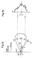
- FIG. 1a An example of a conventional radar geometry and the corresponding azimuth spectrum is shown in FIG. 1a.
- a carrier of a radar system in the form of a schematically indicated aircraft 1 should fly at a speed V ′′ and have a speed error V b in the direction of view of an antenna, not shown, whose main lobe is shown schematically, the opening angle of which in the present case is of the order of magnitude is approximately 17.degree.
- the two speed quantities Vy and V b are dependent on the time t and are therefore referred to in the drawing and below as V " (t) and V b (t), respectively.
- each backscatter signal contains a frequency or Doppler offset according to the following GI. (1): the angle between the radar line of sight to the respective point target and the line perpendicular to the flight path (which runs through the target point B in the example shown) and is denoted by the wavelength of the radar pulses emitted.
- a positive frequency offset is generated for the point target A with an angle 9> 0 and with the airspeed V v (t), while for the point target C with an airspeed V v (t) a negative frequency offset is generated with an airspeed ⁇ 0.
- Fig.lb an azimuth spectrum of the range gate Et is shown schematically, the frequency f being plotted on the vertical axis and the power S with respect to the three point targets A, B and C being plotted on the horizontal axis. Furthermore, to the left of the vertical axis it is indicated that the frequency f is greater than 0 in the positive direction and less than 0 in the negative direction.
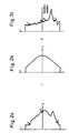
- the azimuth spectrum of a distance gate Et which is schematically represented in FIG. 2a, essentially consists of the product of the antenna diagram shown in FIG. 2b in the azimuth direction and that of the respective target points, for example A, B. and C given and shown in Fig.2c together, where the backscatter ratio is the ratio between the power of a received and a transmitted signal.
- the antenna diagram portion of an azimuth spectrum shown in FIG. 2b is determined by a drift angle and by the speed in the antenna viewing direction according to the following Eq. (2) offset in frequency, where for a frequency offset f a results: where ⁇ (t) is the drift angle of the beam.
- the basic idea in the method for extracting the movement errors of a carrier carrying a coherent imaging radar system is that the two parts of an azimuth spectrum, which are shown schematically in FIGS be evaluated.
- the accuracy of the method depends on the course of the backscatter ratio or on the contrast ⁇ of the azimuth spectrum.
- the contrast T of an azimuth spectrum is defined as follows:
- the contrast T is the Azimuth spectrum small, ie the scatter is approximately equal to 0, so that the spectrum curve or the offset of the backscatter ratio component cannot then be determined exactly. If, however, an area to be imaged has different backscatter ratios, ie has a scattering that is significantly greater than 0, the contrast r is also high and the determination of the spectrum offset is accurate.
- Areas such as the sea, a desert and the like generally have a very low constant backscatter ratio, while areas such as the mainland with cities, meadows, mountains etc. do not have a homogeneous backscatter ratio and thus a high contrast in the azimuth spectrum.
- the respective backscatter ratio component is taken from the azimuth spectrum, which, in contrast to FIG. 2c, has no pronounced maxima in areas with a low contrast 7 , which is why the successive ones are also formed.
- Backscatter ratios are generally relatively similar to one another. This similarity of azimuth spectra recorded in succession is therefore used to estimate the backscatter signal ratio.
- the antenna diagram component can be determined by dividing the azimuth spectrum obtained by the estimated backscatter ratio.
- the accuracy of the estimate increases with more uniform backscatter signal curves, ie with a low contrast T , since the antenna diagram component can then be recognized more and more clearly.
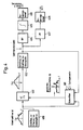
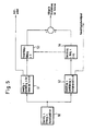
- FIG. 4 A block diagram of a device for carrying out the method for absorbing movement errors of a carrier carrying an imaging radar system, i.e. the so-called (spectrum) focus method is shown in detail in Fig. 4.
- this area is illuminated by means of the main lobe of an antenna attached to an aircraft 1.
- a device 400 for acquiring azimuth spectra is used in succession, i.e. at different times i (where i is an integer value greater than 1) continuously acquires azimuth spectra, this time period for recording the data being much shorter than the time it takes for the aircraft to fly over the area to be imaged.
- the azimuth spectra with a power S (f, i) recorded one after the other as a function of the radar frequency f are passed through a prediction or Cayman filter 401, in which the backscatter ratio portion is taken from the azimuth spectrum, as shown above block 401.
- the backscatter ratio can be determined in this way with great similarity of such azimuth spectra recorded in succession.
- a division unit 402 downstream of the Kalman filter 401 the azimuth spectrum a formed by means 400 is divided by the estimated backscatter ratio b, which is indicated in block 402 by a / b.
- the portion of the antenna diagram shown schematically to the left of block 403 is obtained.
- the center of gravity of the antenna diagram component obtained is then determined in a device 403, which corresponds to the frequency offset f a specified in Eq. (2).
- the drift angle ⁇ (t), which is contained in the first term of Eq. (2), is then achieved by means of a low-pass filter 407 arranged downstream of the device 403, while the speed V b (t) is separated in the direction of view of the distance gate Et of a high-pass filter 404, the speed V b (t) being contained in the second term of GI. (2).
- drift angle 4 ) (t) from the speed V b (t) in the antenna line of sight with the aid of a low or a high-pass filter 407 or 404 is possible since the drift angle caused by the wind has a very low bandwidth of, for example, 0 has up to 0.1 Hz, while the speed V b in the direction of view of the antenna has a much higher bandwidth, only the higher frequency components being important for motion compensation, ie frequency components from 0.2 Hz.
- the frequency components passed through the high-pass filter 404 are subjected to an integration in an integration unit 405 and subsequently standardized in a standardization unit 406, while the frequency components passed through by the low-pass filter 407 are still standardized in a standardization unit 408 .
- the standardization unit 406 receives the storage, ie the deviations in the viewing direction of the antenna, as movement data, while the drift angle ⁇ (t) is obtained at the output of the standardization unit 408.
- the method according to the invention which has also been referred to above again as a focal point method, has the advantage, for example, over the inertial navigation systems mentioned at the outset, which is used in many cases, that the motion extraction method at hand can in principle be implemented considerably more cheaply, and that the necessary calculation processes can be carried out using the methods used today available systems and systems can be carried out particularly easily and quickly both in real time and off-line.
- the method according to the invention can only be used successfully if the area to be imaged has a homogeneous backscatter ratio, ie a low contrast T, which, when imaging the sea or the sea, a desert, etc. the case is.
- a homogeneous backscatter ratio ie a low contrast T
- mapping areas that do not have a homogeneous backscatter ratio ie have a relatively high contrast T , which is the case when mapping areas above the mainland, ie when mapping country, cities, meadows, mountains and the like. the case would be, no exact results could be obtained with the focus method described above.
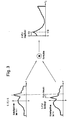
- the offset between two azimuth spectra which are successive in time is therefore evaluated.
- the power S is plotted on the vertical axes as a function of the frequency f on the horizontal axis.
- V (i) of a maximum with respect to the azimuth spectrum is shown in the upper part of FIG. 3 in the lower diagram.
- the area to be imaged must have different backscatter ratios, so that the curves reflecting the backscatter ratio do not have a constant course, as is the case with both azimuth spectra in FIG. 3.
- the course of a backscatter ratio always has a negative frequency shift, since a carrier (1) carrying the radar system always flies in the forward direction and thus all the spreaders, i.e. all objects that are illuminated and backscattered by the radar receive a negative course of the Doppler shift.
- this area is illuminated by means of the main lobe of an antenna attached to an aircraft 1.
- azimuth spectra are continuously recorded.
- the correlation K (f, i), namely K (f, i) S (f, i) 0 S, is formed between each two azimuth spectra with a power S (f, i) recorded one after the other as a function of the radar frequency f (f, i-1).
- the frequency offset V (i) of the backscatter ratio component is then determined on the basis of the position of a maximum, which can be seen schematically in the right part of FIG. 3 and the GI reproduced above. 5) corresponds.
- the separation of the forward speed V v (t), which in the first term of Eq. (5) is included, from the acceleration V b (t) in the direction of view of the distance gate Et, which in the second term of Eq. (5) is included, is carried out using different filtering.
- the forward speed V has a very low bandwidth in wind gusts of up to 1 m / s, for example of 0 ranges up to 0.1 Hz.
- the acceleration V b in the antenna line of sight has a much larger bandwidth, on top of which only the higher frequency components are important for motion compensation, for example only frequency components from 0.2 Hz to be taken into account.
- the data let through during the filtering are integrated and subsequently normalized, while the frequency components allowed to determine the forward speed only have to be standardized in order to then store the motion data, i.e. to get the deviation in the antenna line of sight as well as the forward speed.
- a targeted application of the two aforementioned methods is achieved in an optimal manner if the contrast of an azimuth spectrum is continuously evaluated and the method, which in each case delivers the more precise values, is given more weight when determining the offset, i.e. the deviation is given in the viewing direction.
- FIG. 5 shows a block diagram for linking the two methods.
- the azimuth spectrum has a low contrast ⁇ , so that the most accurate result is obtained with the so-called focus method according to the invention.
- its azimuth spectrum will have a high contrast T , so that the method using the backscattering ratio component provides the most accurate result.
- a weighting of the two methods is determined in FIG. 5 by a factor k.
- the factor k will assume values between 0 and 1; in practice this means that for low contrasts T , ie T - 0, the factor k goes against 1 (ie k - 1), while for high contrasts ⁇ , ie r »0, the factor k approaches 0, ie k - 0 goes.
- a device 51 for performing azimuth spectra, a device 51 for carrying out the method with low contrast ⁇ ( T - 0) and a device 53 for forming the Factor k is connected downstream, while a device 52 for carrying out the offset method (with a contrast 0) or the normalization unit 45, as shown in detail in FIG. 4, is followed by a device 54 for forming the difference (1-k).
Landscapes
- Engineering & Computer Science (AREA)
- Remote Sensing (AREA)
- Radar, Positioning & Navigation (AREA)
- Physics & Mathematics (AREA)
- Signal Processing (AREA)
- Electromagnetism (AREA)
- Computer Networks & Wireless Communication (AREA)
- General Physics & Mathematics (AREA)
- Radar Systems Or Details Thereof (AREA)
Applications Claiming Priority (2)
| Application Number | Priority Date | Filing Date | Title |
|---|---|---|---|
| DE3922427 | 1989-07-07 | ||
| DE3922427A DE3922427C1 (fr) | 1989-07-07 | 1989-07-07 |
Publications (3)
| Publication Number | Publication Date |
|---|---|
| EP0406879A2 true EP0406879A2 (fr) | 1991-01-09 |
| EP0406879A3 EP0406879A3 (en) | 1991-09-04 |
| EP0406879B1 EP0406879B1 (fr) | 1995-04-12 |
Family
ID=6384528
Family Applications (1)
| Application Number | Title | Priority Date | Filing Date |
|---|---|---|---|
| EP90112924A Expired - Lifetime EP0406879B1 (fr) | 1989-07-07 | 1990-07-06 | Méthode d'extraction d'erreurs de mouvement d'un porteur transportant un système radar d'imagerie cohérent à partir de données radar brutes et dispositif pour la mise en oeuvre de ce procédé |
Country Status (4)
| Country | Link |
|---|---|
| US (1) | US5045855A (fr) |
| EP (1) | EP0406879B1 (fr) |
| CA (1) | CA2020644C (fr) |
| DE (2) | DE3922427C1 (fr) |
Cited By (3)
| Publication number | Priority date | Publication date | Assignee | Title |
|---|---|---|---|---|
| EP0562129A1 (fr) * | 1992-03-03 | 1993-09-29 | Deutsches Zentrum für Luft- und Raumfahrt e.V. | Procédé et dispositif pour l'extraction des erreurs de mouvement d'une plateforme transportant un système de radar cohérent d'imagerie |
| FR2703789A1 (fr) * | 1993-04-08 | 1994-10-14 | Deutsche Forsch Luft Raumfahrt | Procédé et dispositif d'extraction, d'erreurs de mouvement d'un réacteur sur lequel est monté un système radar cohérent de formation d'image à partir de données brutes du radar . |
| GB2341995A (en) * | 1998-07-31 | 2000-03-29 | Litton Systems Inc | INS/GPS motion compensation for synthetic aperture radar |
Families Citing this family (20)
| Publication number | Priority date | Publication date | Assignee | Title |
|---|---|---|---|---|
| DE3922428A1 (de) * | 1989-07-07 | 1991-01-17 | Deutsche Forsch Luft Raumfahrt | Verfahren zur extraktion von bewegungsfehlern eines ein kohaerentes abbildungsradarsystem mitfuehrenden traegers aus radar-rohdaten und einrichtung zur durchfuehrung des verfahrens |
| DE4124062C1 (fr) * | 1991-07-19 | 1992-09-03 | Deutsche Forschungsanstalt Fuer Luft- Und Raumfahrt Ev, 5300 Bonn, De | |
| US5343203A (en) * | 1992-09-24 | 1994-08-30 | Hughes Aircraft Company | Doppler tracking method for object imaging from radar returns |
| DE4323511C1 (de) * | 1993-07-14 | 1995-01-26 | Deutsche Aerospace | Radargerät zur Hinderniswarnung |
| US5614907A (en) * | 1996-03-14 | 1997-03-25 | Daimler-Benz Aerospace Ag | All weather visual system for helicopters |
| SE511509C3 (sv) * | 1997-12-23 | 1999-11-22 | Ericsson Telefon Ab L M | Metod foer att optimera taeckningsomraadet foer en sensor |
| FR2886020B1 (fr) * | 2005-05-19 | 2007-10-19 | Eurocopter France | Systeme d'estimation de la vitesse d'un aeronef et son application a la detection d'obstacles |
| US9562788B1 (en) * | 2011-09-30 | 2017-02-07 | Rockwell Collins, Inc. | System and method for doppler aided navigation using weather radar |
| US9939526B2 (en) | 2007-09-06 | 2018-04-10 | Rockwell Collins, Inc. | Display system and method using weather radar sensing |
| US9733349B1 (en) | 2007-09-06 | 2017-08-15 | Rockwell Collins, Inc. | System for and method of radar data processing for low visibility landing applications |
| US9354633B1 (en) | 2008-10-31 | 2016-05-31 | Rockwell Collins, Inc. | System and method for ground navigation |
| CA2802784C (fr) * | 2010-06-28 | 2016-03-15 | Institut National D'optique | Procede et appareil de compensation d'un changement de parametre dans un systeme d'imagerie a ouverture synthetique |
| US8909471B1 (en) | 2011-09-30 | 2014-12-09 | Rockwell Collins, Inc. | Voting system and method using doppler aided navigation |
| US8952841B1 (en) * | 2012-01-13 | 2015-02-10 | Rockwell Collins, Inc. | System and method for TCAS based navigation |
| US9262932B1 (en) | 2013-04-05 | 2016-02-16 | Rockwell Collins, Inc. | Extended runway centerline systems and methods |
| US10928510B1 (en) | 2014-09-10 | 2021-02-23 | Rockwell Collins, Inc. | System for and method of image processing for low visibility landing applications |
| US10705201B1 (en) | 2015-08-31 | 2020-07-07 | Rockwell Collins, Inc. | Radar beam sharpening system and method |
| US10228460B1 (en) | 2016-05-26 | 2019-03-12 | Rockwell Collins, Inc. | Weather radar enabled low visibility operation system and method |
| US10353068B1 (en) | 2016-07-28 | 2019-07-16 | Rockwell Collins, Inc. | Weather radar enabled offshore operation system and method |
| CN111220992B (zh) * | 2018-11-26 | 2022-05-20 | 长沙智能驾驶研究院有限公司 | 雷达数据融合方法、装置及系统 |
Family Cites Families (7)
| Publication number | Priority date | Publication date | Assignee | Title |
|---|---|---|---|---|
| US4359732A (en) * | 1963-11-21 | 1982-11-16 | Goodyear Aerospace Corporation | Topographical mapping radar |
| GB2069281B (en) * | 1979-07-31 | 1983-08-10 | Marconi Co Ltd | Doppler radar system |
| GB2185651B (en) * | 1979-10-19 | 1988-01-27 | Emi Ltd | Synthetic aperture radar |
| GB2185869B (en) * | 1979-10-19 | 1987-12-23 | Emi Ltd | Doppler technique of synthetic aperture radar motion compensation |
| US4771287A (en) * | 1983-06-23 | 1988-09-13 | Westinghouse Electric Corp. | Method of correcting for errors in radar imaging |
| GB8630315D0 (en) * | 1986-12-18 | 1987-04-15 | Gen Electric Co Plc | Synthetic aperture radar |
| GB8714746D0 (en) * | 1987-06-24 | 1987-07-29 | Secr Defence | Synthetic aperture radar |
-
1989
- 1989-07-07 DE DE3922427A patent/DE3922427C1/de not_active Expired - Lifetime
-
1990
- 1990-07-06 EP EP90112924A patent/EP0406879B1/fr not_active Expired - Lifetime
- 1990-07-06 CA CA002020644A patent/CA2020644C/fr not_active Expired - Fee Related
- 1990-07-06 US US07/548,792 patent/US5045855A/en not_active Expired - Fee Related
- 1990-07-06 DE DE59008881T patent/DE59008881D1/de not_active Expired - Fee Related
Cited By (4)
| Publication number | Priority date | Publication date | Assignee | Title |
|---|---|---|---|---|
| EP0562129A1 (fr) * | 1992-03-03 | 1993-09-29 | Deutsches Zentrum für Luft- und Raumfahrt e.V. | Procédé et dispositif pour l'extraction des erreurs de mouvement d'une plateforme transportant un système de radar cohérent d'imagerie |
| FR2703789A1 (fr) * | 1993-04-08 | 1994-10-14 | Deutsche Forsch Luft Raumfahrt | Procédé et dispositif d'extraction, d'erreurs de mouvement d'un réacteur sur lequel est monté un système radar cohérent de formation d'image à partir de données brutes du radar . |
| GB2341995A (en) * | 1998-07-31 | 2000-03-29 | Litton Systems Inc | INS/GPS motion compensation for synthetic aperture radar |
| GB2341995B (en) * | 1998-07-31 | 2003-02-19 | Litton Systems Inc | Enhanced motion compensation technique in synthetic aperture radar systems |
Also Published As
| Publication number | Publication date |
|---|---|
| CA2020644C (fr) | 1995-01-31 |
| DE59008881D1 (de) | 1995-05-18 |
| EP0406879B1 (fr) | 1995-04-12 |
| EP0406879A3 (en) | 1991-09-04 |
| DE3922427C1 (fr) | 1991-01-24 |
| CA2020644A1 (fr) | 1991-01-08 |
| US5045855A (en) | 1991-09-03 |
Similar Documents
| Publication | Publication Date | Title |
|---|---|---|
| EP0406877B1 (fr) | Méthode d'extraction d'erreurs de mouvement d'un porteur transportant un système radar d'imagerie cohérent à partir de données brutes et dispositif pour la mise en oeuvre de ce procédé | |
| EP0406879B1 (fr) | Méthode d'extraction d'erreurs de mouvement d'un porteur transportant un système radar d'imagerie cohérent à partir de données radar brutes et dispositif pour la mise en oeuvre de ce procédé | |
| DE69021354T2 (de) | System zur Detektion eines Hindernisses. | |
| DE69922391T2 (de) | Höhenmesserradar mit interferometrischsynthetischer apertur | |
| DE102006009121B4 (de) | Verfahren zur Verarbeitung und Darstellung von mittels Synthetik-Apertur-Radarsystemen (SAR) gewonnen Bodenbildern | |
| DE4423899C1 (de) | Verfahren zur Detektion, Lokalisierung und Geschwindigkeitsbestimmung von Bewegtzielen aus Radar-Rohdaten eines von einem Träger mitgeführten, kohärenten, ein- oder mehrkanaligen Abbildungssystems | |
| DE69026583T2 (de) | Radar mit synthetischer Apertur und Strahlkeulenschärfungsfähigkeit in der Richtung der Fahrt | |
| DE69606094T2 (de) | Radarverfahren und Vorrichtung, die Ziele in Clutterbereichen mittels der Intensität und der Winkellage der Ziele erfassen | |
| DE3442598C2 (de) | Leitsystem für Flugkörper | |
| EP1273518B1 (fr) | Configuration de satellites d'imagerie interférométrique et/ou tomographique de la surface terrestre avec radar d'aperture synthétique | |
| EP1065518A2 (fr) | Radar à aperture synthétique avec grande résolution | |
| DE102021211743A1 (de) | Verfahren und Vorrichtung zum Bereitstellen von Tracking-Daten für die Erkennung der Bewegung von Personen und Händen zum Steuern mindestens einer Funktion eines Technischen Systems und Sensorsystem | |
| DE1591312A1 (de) | Impulsverfahren zur Richtungsfindung | |
| DE4311754C1 (de) | Verfahren zur Extraktion von Bewegungsfehlern eines ein kohärentes Abbildungsradarsystem mitführenden Trägers aus Radar-Rohdaten und Einrichtung zur Durchführung des Verfahrens | |
| DE602005001113T2 (de) | Verfahren zur Abbildung einer Zielszene mittels Abtastradar | |
| EP1515159A1 (fr) | Méthode pour réduire le centroide doppler pour des systèmes radar coherent à impulsion | |
| DE2133395C3 (de) | Einrichtung zur Kompensation der Eigenbewegung einer kohärenten Impuls-Doppler-Radaranlage | |
| DE4233416C2 (de) | Radargerät mit synthetischer Apertur auf der Basis rotierender Antennen | |
| DE4124062C1 (fr) | ||
| DE69222024T2 (de) | Verfahren und Vorrichtung zur Extraktion von Bewegungsfehlern einer ein kohärentes Abbildungsradarsystem tragenden Plattform | |
| DE3110691A1 (de) | Navigations- und lenksystem fuer flugkoerper | |
| WO1998045726A1 (fr) | Procede pour surveiller la surface de la terre | |
| DE102004061486B4 (de) | Verfahren zur Signaldatenverarbeitung eines fluggerätegetragenen Radars mit synthetischer Apertur und eine Vorrichtung dafür | |
| EP0076877B1 (fr) | Dispositif pour l'affichage d'une parcelle de terrain à bord de véhicules, particulièrement d'avions | |
| DE19912370A1 (de) | Verfahren zur Radarsignalverarbeitung und Radaranordnung insbesondere in einem Kraftfahrzeug |
Legal Events
| Date | Code | Title | Description |
|---|---|---|---|
| PUAI | Public reference made under article 153(3) epc to a published international application that has entered the european phase |
Free format text: ORIGINAL CODE: 0009012 |
|
| AK | Designated contracting states |
Kind code of ref document: A2 Designated state(s): DE FR GB SE |
|
| PUAL | Search report despatched |
Free format text: ORIGINAL CODE: 0009013 |
|
| AK | Designated contracting states |
Kind code of ref document: A3 Designated state(s): DE FR GB SE |
|
| 17P | Request for examination filed |
Effective date: 19911130 |
|
| 17Q | First examination report despatched |
Effective date: 19931230 |
|
| GRAA | (expected) grant |
Free format text: ORIGINAL CODE: 0009210 |
|
| AK | Designated contracting states |
Kind code of ref document: B1 Designated state(s): DE FR GB SE |
|
| REF | Corresponds to: |
Ref document number: 59008881 Country of ref document: DE Date of ref document: 19950518 |
|
| ET | Fr: translation filed | ||
| GBT | Gb: translation of ep patent filed (gb section 77(6)(a)/1977) |
Effective date: 19950717 |
|
| PLBE | No opposition filed within time limit |
Free format text: ORIGINAL CODE: 0009261 |
|
| STAA | Information on the status of an ep patent application or granted ep patent |
Free format text: STATUS: NO OPPOSITION FILED WITHIN TIME LIMIT |
|
| 26N | No opposition filed | ||
| PGFP | Annual fee paid to national office [announced via postgrant information from national office to epo] |
Ref country code: DE Payment date: 19980708 Year of fee payment: 9 |
|
| PGFP | Annual fee paid to national office [announced via postgrant information from national office to epo] |
Ref country code: GB Payment date: 19980720 Year of fee payment: 9 Ref country code: FR Payment date: 19980720 Year of fee payment: 9 |
|
| PGFP | Annual fee paid to national office [announced via postgrant information from national office to epo] |
Ref country code: SE Payment date: 19980729 Year of fee payment: 9 |
|
| PG25 | Lapsed in a contracting state [announced via postgrant information from national office to epo] |
Ref country code: GB Free format text: LAPSE BECAUSE OF NON-PAYMENT OF DUE FEES Effective date: 19990706 |
|
| PG25 | Lapsed in a contracting state [announced via postgrant information from national office to epo] |
Ref country code: SE Free format text: THE PATENT HAS BEEN ANNULLED BY A DECISION OF A NATIONAL AUTHORITY Effective date: 19990730 |
|
| PG25 | Lapsed in a contracting state [announced via postgrant information from national office to epo] |
Ref country code: FR Free format text: THE PATENT HAS BEEN ANNULLED BY A DECISION OF A NATIONAL AUTHORITY Effective date: 19990731 |
|
| GBPC | Gb: european patent ceased through non-payment of renewal fee |
Effective date: 19990706 |
|
| EUG | Se: european patent has lapsed |
Ref document number: 90112924.7 |
|
| PG25 | Lapsed in a contracting state [announced via postgrant information from national office to epo] |
Ref country code: DE Free format text: LAPSE BECAUSE OF NON-PAYMENT OF DUE FEES Effective date: 20000503 |
|
| REG | Reference to a national code |
Ref country code: FR Ref legal event code: ST |