EP0407128B1 - Procédé et dispositif pour l'évaluation d'une sonde lambda - Google Patents
Procédé et dispositif pour l'évaluation d'une sonde lambda Download PDFInfo
- Publication number
- EP0407128B1 EP0407128B1 EP90307219A EP90307219A EP0407128B1 EP 0407128 B1 EP0407128 B1 EP 0407128B1 EP 90307219 A EP90307219 A EP 90307219A EP 90307219 A EP90307219 A EP 90307219A EP 0407128 B1 EP0407128 B1 EP 0407128B1
- Authority
- EP
- European Patent Office
- Prior art keywords
- gas
- supply
- burnt
- additional
- sensor
- Prior art date
- Legal status (The legal status is an assumption and is not a legal conclusion. Google has not performed a legal analysis and makes no representation as to the accuracy of the status listed.)
- Expired - Lifetime
Links
Images





Classifications
-
- G—PHYSICS
- G01—MEASURING; TESTING
- G01N—INVESTIGATING OR ANALYSING MATERIALS BY DETERMINING THEIR CHEMICAL OR PHYSICAL PROPERTIES
- G01N33/00—Investigating or analysing materials by specific methods not covered by groups G01N1/00 - G01N31/00
- G01N33/0004—Gaseous mixtures, e.g. polluted air
- G01N33/0009—General constructional details of gas analysers, e.g. portable test equipment
- G01N33/007—Arrangements to check the analyser
-
- G—PHYSICS
- G01—MEASURING; TESTING
- G01N—INVESTIGATING OR ANALYSING MATERIALS BY DETERMINING THEIR CHEMICAL OR PHYSICAL PROPERTIES
- G01N27/00—Investigating or analysing materials by the use of electric, electrochemical, or magnetic means
- G01N27/26—Investigating or analysing materials by the use of electric, electrochemical, or magnetic means by investigating electrochemical variables; by using electrolysis or electrophoresis
- G01N27/403—Cells and electrode assemblies
- G01N27/406—Cells and probes with solid electrolytes
- G01N27/4065—Circuit arrangements specially adapted therefor
Definitions
- the present invention relates to a method of evaluating the performance of air-fuel ratio sensors and more particularly a method of measuring the properties of oxygen sensors consisting of solid electrolyte used for detecting the air-fuel ratio of exhaust gas from an internal combustion engines, and an apparatus for effecting such an evaluating method.
- the evaluation of properties of the oxygen sensor which is used in the exhaust gas from the internal combustion engines in motor vehicles is effected by actually mounting the oxygen sensor to be measured on the internal combustion engine.
- the results of measurements are variable depending on the kind of engine, control systems, sensor set positions, running conditions, and circumferential conditions (temperature, humidity, pressure).
- there are problems of stability and economics of measurement since a lot of time and steps are required for measuring the properties of the sensors. Therefore, the measurement of properties can not be practically effected on the actual engine.
- model gas in which various kinds of gas supplied from bombs are used to prepare a test gas mixture having a composition as similar as possible to the exhaust gas and the sensor and the test gas mixture are electrically heated under controlled conditions
- combustion gas in which a fuel gas such as propane, city gas or the like is burnt and this burnt gas is used to measure the properties of the oxygen sensor to be measured.
- the model gas method is excellent on strictness and stability of measuring conditions, but is mainly used in the laboratory field, since it is expensive and the treating capacity is limited. Therefore, the model gas method is not practical for measuring the performance of a number of sensors.
- the combustion method using a gas burner is economical and easily practicable and has a high treating capacity for measuring the performance of a number of sensors, but it cannot satisfactorily represent the performance measured on the actual engine.
- FIG. 14 An example of an apparatus adapted for carrying out the conventional combustion as method is illustrated in Fig. 14, which is disclosed in a thesis "Characteristics of ZrO2-Type Oxygen Sensors for Automotive Applications” presented by C.T. Young and J.D. Bode in Detroit, February 26 ⁇ March 2, 1979 as the SAE Technical Paper Series No. 790143.
- fuel gas and air are supplied from fuel gas supplies 51-1 and 51-2 and air supplies 52-1 and 52-2 via gas flow adjusting solenoid valves 53-1 and 53-2, respectively, to a gas burner 54 to mix the fuel gas with air and then burn the gas mixture.
- the burnt gas from the gas burner is supplied into a cylindrical port 55 which is provided with an oxygen sensor 56 to be measured.
- the measured data from the oxygen sensor 56 is processed in a measuring device 57 which outputs signals to control a solenoid valve actuator 58.
- burnt gas can be obtained simply by burning the gas mixture in the gas burner 54 and then a lot of burnt gas can be supplied in a simple manner.
- the composition of the burnt gas however can only be controlled by changing the air-fuel ratio of fuel gas and air supplied to the gas burner 54.
- the burnt gas cannot perfectly imitate the exhaust gas from an actual internal combustion engine since the gas mixture is burnt under conditions of complete combustion and thus the amount of unburned gas is small. Furthermore, in the aforementioned apparatus, only a detecting portion of the oxygen sensor 56 is exposed to the burnt gas flow in the cylindrical port 55 so that the burnt gas flow can not sufficiently contact the detecting portion of the oxygen sensor 56 for a short time and consequently the properties of the sensor can not be accurately evaluated.
- EP 273765 describes an apparatus for evaluating an oxygen sensor, in which a combustion gas supplied to the oxygen sensor has its composition vary, by the injection of exhaust gas or air, and the resultant mixture is cycled between rich and lean phases at 0.5 second intervals.
- JP-A-57-208443 discloses another apparatus for evaluating the performance of an oxygen sensor, in which the composition of the combustion gases are cyclicly varied to change the air-fuel ratio, by applying a varying air-fuel ratio to the combustion region.
- the supply rate of the additional gas is increased and decreased in cycle or stepwise with a frequency of at least 10 Hz and a ratio of high supply rate to low supply rate is controlled to change the average supply rate of the additional gas. Accordingly, the supply rate of the additional gas can be changed with high frequency (at least ten times per second) and therefore the excess air ratio (expressed by ⁇ hereinafter) can be finely controlled.
- the frequency of increasing and decreasing supply rate of the additional gas is at least 10 Hz, since an electronic fuel injection engine has the same minimum fuel injection frequency. That is, most of the electronic fuel injection engines effect one fuel injection per one revolution and then the fuel injection frequency in a range of normal number of revolutions of 650 rpm ⁇ 6000 rpm is in a range of 10.8 Hz ⁇ 100 Hz.
- the frequency of increasing and decreasing supply rate of the additional gas is set at least 10 Hz
- the additional oxidation gas and reduction gas can be repeatedly increased and decreased with a frequency of at least ten times per second and after the burnt gas is mixed with the additional gases, the value of ⁇ of the mixed gas is compensated. Accordingly, even if the flow rate of the additional gases is large, the variation range of ⁇ can be reduced and the measuring ⁇ range can be accurately set in the proximity of the ⁇ of the engine exhaust gas. Consequently, the properties of the oxygen sensors can be measured in a high correlation with values measured on actual engine.
- Fig. 1 shows an embodiment of the apparatus for evaluating air-fuel ratio sensors according to the present invention.
- fuel gas and air as combustion base gas are supplied to a gas burner 1 from a fuel gas supply 3 and an air supply 4 of a primary gas supply 2 and burnt in the gas burner 1 to produce burnt gas having a predetermined air-fuel ratio.
- the burnt gas flows from the gas burner to a sensor to be measured within a cylindrical port 6.
- a controlled amount of oxidation gas or reduction gas is supplied into the cylindrical port 6 between the gas burner 1 and sensor 7 from an oxidation gas supply 9 or a reduction gas supply 10 of an additional gas supply by controlling a solenoid valve 11-1 or 12-1.
- relief valves 11-2 and 12-2 are connected to the oxidation gas supply 9 and the reduction gas supply 10 in parallel to the solenoid valve 11-1 and 12-1, respectively, to increase the flow of gas when the flow through the solenoid valves 11-1 and 12-1 decreases, and to decrease when the flow through the solenoid valves 11-1 -and 12-1 increases to thereby maintain a constant pressure in the line by use of relief valves by maintain additional gas supply varies.
- the senor 7 outputs detected signals to a feedback controller 13 to process the signals.
- the controller 13 outputs control signals to a solenoid valve driver 14 to control solenoid valves 11-1, 11-2, 12-1 and 12-2 to thereby prepare a gas mixture having a predetermined composition.
- the sensor 7 also supplies output signals to a data processor 15 to process the signals together with results measured by a ⁇ detector 16 which detects an atmosphere at the tip end of the cylindrical port 6 to thereby evaluate properties of the sensor to be measured.
- the gas burner 1 and the primary gas supply 2 constitute the burnt gas producing part
- a portion of the cylindrical port 6 constitutes the measuring part
- a portion of the cylindrical port 6 constitutes the connecting part
- the additional gas supply 8 and the solenoid valve 11-1, 12-1 constitute the additional gas introducing part
- a portion of the feedback controller 13 and the electromagnetic driver 14 constitute the gas flow rate controlling part
- a portion of the feedback controller 13 constitutes the pulse width controlling part.
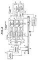
- Fig. 2 is a block diagram showing an embodiment of a feedback controller together with waveforms of signals output from respective parts.
- the sensor 7 outputs signals to a comparator 21.
- the sensor to be measured is the normal ZrO2 type solid electrolyte oxygen sensor, its output voltage in a lean atmosphere is at most 200 mV (hereinafter, termed lean voltage) and the output voltage in a rich atmosphere is at least 700 mV (hereinafter, termed rich voltage).
- an intermediate voltage between the rich voltage and the lean voltage (for example 450 mV) is used as the reference voltage to transduce the sensor output voltage in the comparator 21 to a pulse wave form (a) as shown in the drawing.
- the pulse signal is supplied to an integral operation regulator 22 to transduce the pulse wave form to a sawtooth wave form (b), and thirdly the signal is supplied to a skip operation regulator 23 to transduce the wave form (b) to another wave form (c) as shown in the drawing.
- a pulse generator 24 outputs a pulse signal having a constant frequency of at least 10 Hz.
- a pulse width modulator 26 modulates the pulse width of a signal (d) together with the signal (c) which has been skip transduced to output a feedback controlling pulse signal (e) which has the same frequency and a different duty ratio.
- This feedback controlling pulse signal is supplied to the solenoid valve driver 14 to control the supply amount of the additional gas supplied to the cylindrical port 6 in such a manner that the flow rate of the gas is increased when the pulse signal is positive and the flow rate is decreased when the pulse signal is negative.
- the solenoid valve 11-1 and 12-1 for discontinuously supplying the oxidation gas and reduction gas respectively operate in such a manner that when the oxidation gas is increased, the reduction gas is decreased and when the oxidation gas is decreased, the reduction gas is increased.
- the feedback control signal is added with an integral operation and a skip operation each of which can be voluntarily set. Accordingly, the integral operation and the skip operation can be regulated to match easily to feedback properties of various engines.
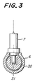
- Fig. 3 is a partially sectional view of the sensor measuring part in the apparatus shown in Fig. 1.
- a throttle member 32 is arranged around a detecting portion 31 of the sensor 7 in the cylindrical port 6 to locally limit the gas flow passage of the cylindrical port at the sensor mounting portion.
- the burnt gas from the burnt gas producing part for use in measurement has a flow rate and pressure lower than those of exhaust gas discharged from an engine and a difference in responsiveness from the value measured using engine exhaust gas may arise depending on the configuration of the detecting portion 31 of the sensor 7 and the tip vent mechanism. Therefore, the sectional area of the gas flow passage at the sensor mount position is limited to increase the flow resistance around the detecting portion of the sensor to thereby increase the substituting speed of the test gas in the sensor. As the result, a response relationship similar to an engine can be obtained and the gas flow rate required can be economically reduced.
- Fig. 4 is a block diagram showing another embodiment of the apparatus for evaluating an air-fuel ratio sensor according to the present invention.
- portions corresponding to those shown in Fig. 1 are designated by the same reference numeral and no detailed description is given here.
- the embodiment of Fig. 4 is different from the embodiment shown in Fig. 1 in that the air supply 4 consists of an air supply part 4-1 and a mass flow controller 4-2 (hereinafter, called MFC for short) and the fuel gas supply 3 consists of a fuel gas supplying part 3-1 and MFC 3-2. Moreover, a large range air-fuel ratio sensor 35 is arranged downstream of the gas burner 1. The sensor 35 outputs to a primary gas ⁇ controller 36 which controls the MFC 3-2. Consequently, the ⁇ can be accurately maintained a constant.
- the additional gas supply 8 includes an oxidation gas supply 9 for supplying air, a reduction gas supply 10 for supplying CO gas and a further reduction gas supply 36 for supplying H2 gas.
- the reduction gas supply 36 also supplies H2 gas through the same supply port together with the air and CO gas under the control of the solenoid valves 37-1 and 37-2 to make the burnt gas similar to the exhaust gas. Furthermore, a large range air-fuel ratio sensor 38 is arranged in place of the ⁇ detector 16 to determine the properties of the sensor to be measured.
- the arrangement of the feedback controller 13 in this embodiment is the same as that shown in Fig. 2.
- the gas burner 1 and the primary gas supply 2 constitute the burnt gas producing part
- a portion of the cylindrical port 6 constitutes the measuring part
- a portion of the cylindrical port 6 constitutes the connecting part
- the additional gas supply 8 and the solenoid valves 11-1, 12-1 and 37-1 constitute the additional gas introducing part
- a portion of the feedback controller 13 and the solenoid valve driver 14 constitute the gas flow rate controlling part
- a portion of the feedback controller 13 constitutes the pulse width controlling part.
- the primary gas and the additional gas were supplied at the flow rate shown in Table 1 and the frequency of open and close operation of the solenoid valve was 20 Hz.
- the increasing and decreasing of the additional gas was feedback controlled so as to maintain the measuring sensor at a predetermined voltage (for example 450 mV) and the excess air ratio ⁇ AVG and the feedback frequency F B was measured.
- the same sensor to be measured was mounted on an actual internal combustion engine. This engine was driven at 1150 rpm and the excess air ratio ⁇ AVG and the feedback frequency F LC was measured during feedback controlling by the sensor.
- Fig. 5 shows a correlation of excess air ratio
- Fig. 6 shows a correlation of feedback frequency. It will be seen from the results shown in Figs.
- the dispersion of the excess air ratio ⁇ was determined for the cases that the distance (L) from the additional gas mixing part to a position of the sensor to be measured is respectively 10 times and 3 times the inner diameter "d" of the cylindrical port 6 shown in Fig. 4.
- Fig. 11 shows another embodiment of the apparatus for evaluating an air-fuel ratio sensor according to the present invention.
- This embodiment is adapted for an open loop measurement, but not the feedback control as mentioned above.
- portions corresponding to those shown in Fig. 1 are designated by the same reference numeral and no detailed description is given here.
- the sensor 7 to be measured directly supplies output to the data processor 15, and a controller 41 which differs from the feedback controller 13 of Fig.1 is provided to cooperate with a programmer 42 so as to control the solenoid valve driver 14 to thereby increase and decrease the supply of the additional gas at high speed.
- the gas burner 1 and the primary gas supply 2 constitute the burnt gas producing part
- a portion of the cylindrical part 6 constitutes the connecting part
- the additional gas supply 8 and the solenoid valve 11-1 ⁇ 12-1 constitute the additional gas introducing part
- a portion of the controller 41 and the solenoid valve driver 41 constitute the gas flow rate controlling part
- a portion of the controller 41 constitutes the pulse width controlling part.
- a programmer 42 firstly generates a pulse-like signal (a) which is limited to an output of a sensor 7 to be measured.
- a pulse generator 43 generates a pulse signal (b) of a constant frequency of at least 10 Hz, and the pulse-like signal (a) from the programmer 42 and the pulse signal (b) from the pulse generator 43 are supplied to a pulse width modulator 45 to modulate, thereby obtaining a controlling pulse signal (c).
- the controlling pulse signal (C) changes its duty ratio by every several pulse signals, and if the pulse-like signal from the programmer 42 has a waveform (B) which is changed to coincide with ⁇ variation in an engine, the controlling pulse signal (d) has different duty ratio by every pulse signal.
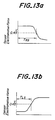
- Figs. 13a and 13b are graphs showing the variation of sensor electromotive force by every switching operation in the above described operation in the above described embodiment.
- T RS and T LS are response times from generation of respective solenoid valve switching signals to the time when the sensor electromotive force becomes a predetermined value (0.45 V in this embodiment).
- T LS shows the time for varying the sensor electromotive force from the rich side to a predetermined value
- T LS shows the time for varying the sensor electromotive force from the lean side to a predetermined value, respectively.
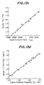
- the data processor 15 can evaluate properties of the sensor 7 by using 1/(T RS +T LS ) and T RS /T LS as an index of property evaluation.
- Figs. 13c and 13d show an example of the evaluation. It will be seen from Figs. 13c and 13d that the values measured in an actual engine correlates well with the results evaluated according to the present invention.
- the gas control response is better than that of a thermal type mass flow controller, a flow rate can continuously be varied, and even if the supply flow rate is large, a small ⁇ variation can be set with high precision.
- the present invention is not limited to the above embodiments, but can be modified in various mode.
- three kinds of CO, H2 and air are used as an additional gas, but in order to imitate an exhaust gas combustion, it is possible to obtain a good result by using further kinds of addition gas or adding other gases such as NO or C3H6, C3H8 and the like represented by C n H 2n and C n H 2n+2 .
- a gas analyzer or an oxygen sensor may be used for measuring a duty ratio to thereby evaluate properties of the sensor to be measured.
Landscapes
- Chemical & Material Sciences (AREA)
- Life Sciences & Earth Sciences (AREA)
- Health & Medical Sciences (AREA)
- Pathology (AREA)
- General Physics & Mathematics (AREA)
- Engineering & Computer Science (AREA)
- Physics & Mathematics (AREA)
- Analytical Chemistry (AREA)
- Biochemistry (AREA)
- General Health & Medical Sciences (AREA)
- Immunology (AREA)
- Chemical Kinetics & Catalysis (AREA)
- Molecular Biology (AREA)
- Electrochemistry (AREA)
- Combustion & Propulsion (AREA)
- Food Science & Technology (AREA)
- Medicinal Chemistry (AREA)
- Investigating Or Analyzing Materials By The Use Of Electric Means (AREA)
- Measuring Oxygen Concentration In Cells (AREA)
Claims (6)
- Procédé d'évaluation des propriétés d'un détecteur d'oxygène (7) utilisé pour détecter le rapport air-carburant d'un gaz d'échappement d'un moteur à combustion interne, comprenant les opérations de préparer un gaz brûlé ayant un rapport à air en excès prédéterminé, de fournir alternativement un gaz d'oxydation et un gaz de réduction comme gaz additionnel au gaz brûlé pour former un écoulement de gaz mélangé, et de détecter la sortie du capteur exposée à l'écoulement de gaz mélangé, où le gaz d'oxydation est fourni pour une première période de fourniture et le gaz de réduction est fourni pendant une seconde période de fourniture, lesdites première et seconde périodes de fourniture étant alternantes à une fréquence de cycle prédéterminé, caractérisé en ce que la fréquence de cycle prédéterminé est au moins de 10 Hz, et que le rapport cyclique des premier et second cycles de fourniture dans un cycle varie pour faire varier ainsi le rapport à air en excès (λ) de l'écoulement de gaz mélangé global.
- Procédé pour évaluer les propriétés d'un capteur d'oxygène (7) utilisé pour détecter le rapport air-carburant du gaz d'échappement d'un moteur à combustion interne, comprenant les opérations de préparer un gaz brûlé ayant un rapport à air en excès prédéterminé, de fournir un gaz d'oxydation ou un gaz de réduction comme gaz additionnel au gaz brûlé pour former un écoulement de gaz mélangé, et de détecter une sortie du détecteur exposé à l'écoulement de gaz mélangé, où la fourniture du gaz additionnel effectuée pendant une première période de fourniture et est arrêté pendant une seconde période d'arrêt de fourniture, la première période de fourniture et la seconde période d'arrêt de fourniture étant alternantes à une fréquence de cycle prédéterminée, caractérisé en ce que la fréquence de cycle prédéterminé est au moins de 10 Hz et le rapport cyclique de la première période de fourniture et de la seconde période d'arrêt de fourniture dans un cycle est changé pour changer ainsi le rapport à air en excès (λ) de l'écoulement de gaz mélangé dans son ensemble.
- Procédé selon la revendication 1 ou 2, dans lequel la quantité fournie du gaz additionnel est commandée par rétro-action par la sortie du détecteur et les propriétés du détecteur sont évaluées par les propriétés de rétro-action de la commande de rétro-action.
- Un appareil pour évaluer les propriétés d'un capteur d'oxygène qui est utilisé pour détecter le rapport air-carburant d'un gaz d'échappement d'un moteur à combustion interne, comprenant des moyens de production d'un gaz brûlé (31, 2) pour produire un gaz brûlé ayant un rapport à air en excès prédéterminé en brûlant un mélange de gaz de combustion d'un gaz de carburant et de l'air de combustion, une partie de mesure pour recevoir le détecteur d'oxygène (7) devant être évalué, une partie de connexion (6) pour guider un écoulement du gaz brûlé vers la partie de mesure, des moyens d'introduction de gaz additionnel (8, 11, 12) pour introduire alternativement un gaz d'oxydation et un gaz de réduction comme gaz additionnel dans l'écoulement de gaz brûlé, et des moyens de commande de la vitesse d'écoulement de gaz (13, 14; 41) pour commander la vitesse d'écoulement du gaz additionnel introduite dans le gaz brûlé, arrangé pour réaliser une alimentation en gaz d'oxydation pendant une première période d'alimentation ou de fourniture et en gaz réducteur pendant une seconde période de fourniture ou d'alimentation, les première et seconde périodes d'alimentation de fourniture étant alternantes à une fréquence de cycle prédéterminé, caractérisée en ce que les moyens de commande de vitesse d'écoulement de gaz (13, 14, 41) sont adaptées pour que la fréquence de cycle prédéterminé soit au moins de 10 Hz et soit arrangée pour changer le rapport cyclique des première et seconde périodes d'alimentation.
- Un appareil pour évaluer les propriétés d'un capteur d'oxygène qui est utilisé pour détecter le rapport air-carburant d'un gaz d'échappement d'un moteur à combustion interne, comprenant des moyens producteurs de gaz brûlé (31, 32) pour produire un gaz brûlé ayant un rapport à air en excès prédéterminé en brûlant un mélange de gaz de combustion d'un gaz de carburant et de l'air de combustion, une partie de mesure pour recevoir le détecteur d'oxygène (7) devant être évalué, une partie de connexion (6) pour guider un écoulement du gaz brûlé à la partie de mesure, des moyens d'introduction de gaz additionnel (8, 11, 12) pour introduire un gaz d'oxydation ou un gaz réducteur comme gaz additionnel dans l'écoulement de gaz brûlé, et des moyens de commande de vitesse d'écoulement de gaz (13, 14; 41) pour commander et contrôler la vitesse d'écoulement du gaz additionnel introduit dans le gaz brûlé, arrangés de façon que la fourniture de gaz additionnel soit effectuée pendant une première période d'alimentation ou de fourniture et arrêtée pendant une seconde période de fourniture ou d'alimentation et la première période de fourniture et la seconde période d'arrêt de fourniture sont alternantes à une fréquence de cycle prédéterminée, caractérisée en ce que lesdits moyens de commande de vitesse d'écoulement de gaz (13, 14; 41) sont adaptées de façon que la fréquence de cycle prédéterminée soit au moins de 10 Hz et sont arrangés pour changer le rapport cyclique des première et seconde périodes.
- Un appareil selon la revendication 4 ou la revendication 5, caractérisé en ce que les moyens d'introduction de gaz additionnel sont pourvus d'au moins une vanne de sécurité ou de surpression (11-2, 12-2) pour maintenir une pression de fourniture constante du gaz additionnel.
Applications Claiming Priority (2)
| Application Number | Priority Date | Filing Date | Title |
|---|---|---|---|
| JP1168314A JPH0670619B2 (ja) | 1989-07-01 | 1989-07-01 | 空燃比センサ評価法および装置 |
| JP168314/89 | 1989-07-01 |
Publications (2)
| Publication Number | Publication Date |
|---|---|
| EP0407128A1 EP0407128A1 (fr) | 1991-01-09 |
| EP0407128B1 true EP0407128B1 (fr) | 1995-02-22 |
Family
ID=15865738
Family Applications (1)
| Application Number | Title | Priority Date | Filing Date |
|---|---|---|---|
| EP90307219A Expired - Lifetime EP0407128B1 (fr) | 1989-07-01 | 1990-07-02 | Procédé et dispositif pour l'évaluation d'une sonde lambda |
Country Status (4)
| Country | Link |
|---|---|
| US (1) | US5027646A (fr) |
| EP (1) | EP0407128B1 (fr) |
| JP (1) | JPH0670619B2 (fr) |
| DE (1) | DE69017104T2 (fr) |
Families Citing this family (11)
| Publication number | Priority date | Publication date | Assignee | Title |
|---|---|---|---|---|
| JP2827719B2 (ja) * | 1992-07-16 | 1998-11-25 | 三菱自動車工業株式会社 | O2 センサの故障判定方法 |
| DE59306790D1 (de) * | 1993-03-15 | 1997-07-24 | Siemens Ag | Verfahren zur Überprüfung von Lambdasonden |
| JP3262682B2 (ja) * | 1994-11-14 | 2002-03-04 | 株式会社豊田中央研究所 | 空燃比センサ特性解析装置 |
| US5831145A (en) * | 1997-04-30 | 1998-11-03 | Ford Global Technologies, Inc. | Method of introducing selectivity to nonselective gas sensors |
| US5823044A (en) * | 1997-04-30 | 1998-10-20 | Ford Global Technologies, Inc. | Method for selective gas sensors based on nonlinear gas reactions |
| US7090806B1 (en) | 2000-05-01 | 2006-08-15 | Peter Lenehan | Portable oxygen sensor analyzer |
| US6667622B1 (en) | 2000-05-03 | 2003-12-23 | Peter J. Lenehan | Vehicle engine pulse stream analyzer |
| US6481273B2 (en) * | 2001-02-13 | 2002-11-19 | Delphi Technologies, Inc. | Frequency response test method for an in-vehicle air/fuel ratio sensor |
| DE102009047646A1 (de) * | 2009-12-08 | 2011-06-09 | Robert Bosch Gmbh | Verfahren zum Betreiben einer mit einem Gas als Kraftstoff betriebenen Brennkraftmaschine |
| US9606092B2 (en) | 2014-08-07 | 2017-03-28 | Cummins Emission Solutions, Inc. | NOx sensor diagnosis system and method |
| JP2019158758A (ja) * | 2018-03-15 | 2019-09-19 | 日本碍子株式会社 | ガスセンサの応答時間評価装置及び方法 |
Family Cites Families (7)
| Publication number | Priority date | Publication date | Assignee | Title |
|---|---|---|---|---|
| JPS57208442A (en) * | 1981-06-18 | 1982-12-21 | Murata Mfg Co Ltd | Humidity detector |
| JPS57208443A (en) * | 1981-06-18 | 1982-12-21 | Nissan Motor Co Ltd | Apparatus for evaluating performance of oxygen sensor |
| JPS57208441A (en) * | 1981-06-19 | 1982-12-21 | Hitachi Ltd | Detection system of deviation in pattern position by 2-chip comparison |
| US4389881A (en) * | 1981-07-31 | 1983-06-28 | Ford Motor Company | Method of measuring an air to fuel ratio |
| JPH0713600B2 (ja) * | 1986-12-29 | 1995-02-15 | 日本特殊陶業株式会社 | 酸素センサ評価装置 |
| DE3743315A1 (de) * | 1987-12-21 | 1989-06-29 | Bosch Gmbh Robert | Auswerteinrichtung fuer das messsignal einer lambdasonde |
| US4878380A (en) * | 1988-10-03 | 1989-11-07 | Goodman Lynn R | Method of testing catalytic converters and oxygen sensors |
-
1989
- 1989-07-01 JP JP1168314A patent/JPH0670619B2/ja not_active Expired - Fee Related
-
1990
- 1990-07-02 EP EP90307219A patent/EP0407128B1/fr not_active Expired - Lifetime
- 1990-07-02 DE DE69017104T patent/DE69017104T2/de not_active Expired - Fee Related
- 1990-07-02 US US07/546,765 patent/US5027646A/en not_active Expired - Lifetime
Also Published As
| Publication number | Publication date |
|---|---|
| DE69017104T2 (de) | 1995-08-31 |
| EP0407128A1 (fr) | 1991-01-09 |
| DE69017104D1 (de) | 1995-03-30 |
| US5027646A (en) | 1991-07-02 |
| JPH0670619B2 (ja) | 1994-09-07 |
| JPH0335155A (ja) | 1991-02-15 |
Similar Documents
| Publication | Publication Date | Title |
|---|---|---|
| EP0407128B1 (fr) | Procédé et dispositif pour l'évaluation d'une sonde lambda | |
| Reinmann et al. | Local air-fuel ratio measurements using the spark plug as an ionization sensor | |
| JPS6022293B2 (ja) | 内燃機関に供給される燃料混合気の組成を解析しかつ混合気を制御する方法 | |
| US4580539A (en) | Air-fuel ratio control apparatus | |
| EP0576932B1 (fr) | Circuit de commande et d'évaluation pour un capteur de chaleur de réaction | |
| EP0273765B2 (fr) | Appareil pour l'évaluation d'un capteur d'oxygène | |
| JPH0362898B2 (fr) | ||
| EP0152940B1 (fr) | Appareil et méthode de détection de rapport air/carburant | |
| DE19960227A1 (de) | Aktivierungsbestimmungsverfahren und Aktivierungsbestimmungsvorrichtung für einen Luft-Kraftstoff-Verhältnis-Sensor | |
| DE10124129A1 (de) | Vorrichtung und Verfahren zum Messen der Elementtemperatur eines Luft-/Kraftstoffverhältnissensors und Vorrichtung und Verfahren zum Steuern der Heizvorrichung eines Luft-/Kraftstoffverhälntissensors | |
| Nielsen et al. | An ion-sense engine fine-tuner | |
| US20020108432A1 (en) | Frequency response test method for an in-vehicle air/fuel ratio sensor | |
| DE19629554C2 (de) | Verfahren zur Temperaturregelung für eine Lambdasonde | |
| CA2175295C (fr) | Moteur a combustion interne dote d'une sonde d'oxygene avec etalonnage par critere de reference | |
| EP0026642A2 (fr) | Procédé pour commander l'alimentation en carburant pour un moteur à combustion interne | |
| JP2624531B2 (ja) | センサ特性評価法 | |
| GB2327268A (en) | Determining resistance of an exhaust gas concentration sensor | |
| GB2307557A (en) | Exhaust gas sensor and associated circuit arrangement | |
| DE3303617C2 (fr) | ||
| Ueno et al. | Wide-range air-fuel ratio sensor | |
| EP0034013A2 (fr) | Analyse de gaz | |
| US6314953B1 (en) | Method and system for regulating the air/fuel stream fed to an internal-combustion engine | |
| EP0816656A2 (fr) | Dispositif pour détecter le rapport air/carburant et pour commander le rapport air/carburant | |
| JPH02173337A (ja) | 内燃機関における燃空比の調整方法 | |
| JPH0531660B2 (fr) |
Legal Events
| Date | Code | Title | Description |
|---|---|---|---|
| PUAI | Public reference made under article 153(3) epc to a published international application that has entered the european phase |
Free format text: ORIGINAL CODE: 0009012 |
|
| AK | Designated contracting states |
Kind code of ref document: A1 Designated state(s): DE FR GB |
|
| 17P | Request for examination filed |
Effective date: 19910626 |
|
| 17Q | First examination report despatched |
Effective date: 19930428 |
|
| GRAA | (expected) grant |
Free format text: ORIGINAL CODE: 0009210 |
|
| AK | Designated contracting states |
Kind code of ref document: B1 Designated state(s): DE FR GB |
|
| REF | Corresponds to: |
Ref document number: 69017104 Country of ref document: DE Date of ref document: 19950330 |
|
| ET | Fr: translation filed | ||
| PLBE | No opposition filed within time limit |
Free format text: ORIGINAL CODE: 0009261 |
|
| STAA | Information on the status of an ep patent application or granted ep patent |
Free format text: STATUS: NO OPPOSITION FILED WITHIN TIME LIMIT |
|
| 26N | No opposition filed | ||
| REG | Reference to a national code |
Ref country code: GB Ref legal event code: IF02 |
|
| PGFP | Annual fee paid to national office [announced via postgrant information from national office to epo] |
Ref country code: DE Payment date: 20070731 Year of fee payment: 18 |
|
| PGFP | Annual fee paid to national office [announced via postgrant information from national office to epo] |
Ref country code: GB Payment date: 20070618 Year of fee payment: 18 |
|
| PGFP | Annual fee paid to national office [announced via postgrant information from national office to epo] |
Ref country code: FR Payment date: 20070706 Year of fee payment: 18 |
|
| GBPC | Gb: european patent ceased through non-payment of renewal fee |
Effective date: 20080702 |
|
| PG25 | Lapsed in a contracting state [announced via postgrant information from national office to epo] |
Ref country code: DE Free format text: LAPSE BECAUSE OF NON-PAYMENT OF DUE FEES Effective date: 20090203 |
|
| REG | Reference to a national code |
Ref country code: FR Ref legal event code: ST Effective date: 20090331 |
|
| PG25 | Lapsed in a contracting state [announced via postgrant information from national office to epo] |
Ref country code: GB Free format text: LAPSE BECAUSE OF NON-PAYMENT OF DUE FEES Effective date: 20080702 |
|
| PG25 | Lapsed in a contracting state [announced via postgrant information from national office to epo] |
Ref country code: FR Free format text: LAPSE BECAUSE OF NON-PAYMENT OF DUE FEES Effective date: 20080731 |