EP0407226A2 - Leckkabelübertragungssystem - Google Patents
Leckkabelübertragungssystem Download PDFInfo
- Publication number
- EP0407226A2 EP0407226A2 EP90307441A EP90307441A EP0407226A2 EP 0407226 A2 EP0407226 A2 EP 0407226A2 EP 90307441 A EP90307441 A EP 90307441A EP 90307441 A EP90307441 A EP 90307441A EP 0407226 A2 EP0407226 A2 EP 0407226A2
- Authority
- EP
- European Patent Office
- Prior art keywords
- leaky feeder
- transmission system
- cable
- signals
- leaky
- Prior art date
- Legal status (The legal status is an assumption and is not a legal conclusion. Google has not performed a legal analysis and makes no representation as to the accuracy of the status listed.)
- Withdrawn
Links
Images

Classifications
-
- H—ELECTRICITY
- H04—ELECTRIC COMMUNICATION TECHNIQUE
- H04B—TRANSMISSION
- H04B5/00—Near-field transmission systems, e.g. inductive or capacitive transmission systems
- H04B5/20—Near-field transmission systems, e.g. inductive or capacitive transmission systems characterised by the transmission technique; characterised by the transmission medium
- H04B5/28—Near-field transmission systems, e.g. inductive or capacitive transmission systems characterised by the transmission technique; characterised by the transmission medium using the near field of leaky cables, e.g. of leaky coaxial cables
Definitions
- This invention relates to communications systems incorporating so-called leaky feeder cables.
- Leaky feeder communication systems are employed in environments where full radio communication using high power broadcasting is undesirable, for example in terms of feasibility because of channel availability and regulatory conditions, or due to potential hazard. Nevertheless in such environments radiative communication may still be required for purposes such as communication between a mobile station and a base or between mobiles.
- a leaky feeder cable distributed low power transmission occurs along the length of the cable, the cable being disposed along a route such that at any point a mobile station is within range of the low power transmission. In a converse manner the leaky feeder cable also picks up externally generated signals.
- a typical leaky feeder cable may comprise a coaxial cable which has deliberately imperfect screening so that radio frequency signals being conducted along the cable progressively leak from the cable, and externally generated signals are picked up by the cable.
- Our copending UK patent application No. 9013909.8 describes such a system with an additional external housing that itself has discontinuities to enable ingress and egress of signals.
- the present invention is directed towards increasing the potential range of leaky feeder communication systems.
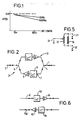
- FIG 1 a typical attenuation/frequency characteristic of a leaky feeder cable over a 500 metre length is shown.
- the rate of attenuation may be around 3dB per 100 metre length.
- the attenuation rate is greater, for example at 500MHz it may be around 10dB per 100 metres.
- the present invention is principally concerned with signal frequencies that may be in the range of 10MHz to 500MHz.
- signal frequencies that may be in the range of 10MHz to 500MHz.
- the available total bandwidth between 10 and 500MHz should generally enable each transmitter to utilise different pre-assigned channels, but for configurations enabling duplication of channel selection a priority interrogation control system can be incorporated.
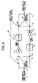
- FIG. 2 and 3 A preferred embodiment of the invention is illustrated in Figures 2 and 3 in which a first leaky feeder cable 1 is connected to a second leaky feeder cable 2 via a repeater 3.
- the leaky feeder cables 1 and 2 may be carrying signals in both directions.
- the repeater comprises asymmetric power couplers 4 and 5.
- the incident signals are predominantly diverted into an output port 6 (Figure3) of power divider 4 and onward into a branch 7 of the repeater.
- This signal is then filtered by a filter 8 to remove unwanted signals and the filtered signal is then amplified by amplifier 9 and applied as an input to a port 10 ( Figure 3) of a power divider 5.
- the amplified signal is then output from the power divider 5 via port 11 and onward into leaky feeder 2, which then continues to conduct onward in the direction leftwards as viewed in the drawing, but at an increased power level compared with the signal incident into coupler 4.
- Figure 4 illustrates schematically a base station launching and receiving signals.
- the base station is connected to a leaky feeder cable 1 which is connected via one or more repeaters (not shown) to further lengths of leaky feeder cable and eventually to a termination (not shown).
- the termination is impedance-matched to the cable to prevent end reflection.
- the base station comprises a transmitter 18 connected via a filter 19 to a port 20 of an asymmetric power divider 21. Transmitted signals pass out into the leaky feeder via port 22 of the power divider.
- the base station also comprises a receiver 23 which receives signals returning to the base station from the leaky feeder cable, these signals being input to port 24 of the power divider and output predominantly via port 22.
- a filter 25 filters out residual transmitted signal from transmitter 18 that appears at port 24, and similarly filter 19 removes unwanted received signal appearing as an output at port 20. Power for the repeaters is transmitted from the base station along the leaky feeder and transferred forward for the next repeater.
- Signals radiated by the leaky feeder are picked up by a mobile receiver 26, and signals may be picked up by the leaky feeder from a mobile transmitter 27.
- the leaky feeder is disposed in a duct or housing which is provided with discontinuities such as perforations, slots or discrete lengths of ducting. This ducting may constitute ruggedisation for the leaky feeder but also may provide RF shielding other than at the discontinuities in order to minimise pick up of ambient RF radiation.
- the power dividers utilised in the embodiment may be as illustrated in Figure 5. Power dividers of this type are known and are for example available from Minicircuits, Brooklyn, New York 11235-0003 (USA).
- the power divider is a three port device having ports 30, 31 and 32, and works generally in one direction as a power divider and in the other direction as a power combiner.
- signal input to a "common" port port 30 is divided as output between the pair of ports 31 and 32, and signals input to port 31 and/or port 32 appear as output at port 30.
- Port 30 is connected to a tap, normally a centre tap on an auto-transformer 33 which is connected between ports 31 and 32, which are also connected by a resistor 34.
- the impedances e.g. the impedance of the cable, the input impedance of the amplifier 15 and the output impedance of the filter 8 in figure 3
- the ports of the pair 31, 32 are substantially isolated from each other.
- ports 31 and 32 which correspond to ports 6 and 16 and 10 and 12 of power dividers 4 and 5 enables isolation between the two directions of signal path shown in Figures 2 and 3 which is necessary in order to inhibit oscillations.
- the gain of the repeater stage needs to be sufficient to compensate for transmission losses in the preceding length of leaky feeder and for the insertion loss of the repeater which is essentially 3dB for each power divider.
- the loss in the leaky feeder cable varies with frequency, and to compensate for this feedback is added to the amplifiers.
- the filters may also compensate for the frequency response of the cable before wide-band amplification to restore power levels.
- the separation between input and output terminals from a node will be 20dB
- the amplifier gain is linear between 5 and 500MHz after correction for the frequency characteristic of the preceding cable.
- Figure 6 illustrates a system in which signal in a given direction is restricted to a respective one of the cables 61 and 62.
- Each section of each cable has a respective filter 63 and amplifier 64 providing a charateristic whci compensates for the loss shown in Figure 1.
- the length of continuous length cable in such a system may be typically between 50 and 2000 m, and the effective length of the feeder may be extended indefinitely by cascading lengths of feeder and active filters and couplers.
- frequency discrimination may be consciously employed to define the performance of such a line for a particular purpose.
Landscapes
- Engineering & Computer Science (AREA)
- Computer Networks & Wireless Communication (AREA)
- Signal Processing (AREA)
- Mobile Radio Communication Systems (AREA)
- Near-Field Transmission Systems (AREA)
Applications Claiming Priority (2)
| Application Number | Priority Date | Filing Date | Title |
|---|---|---|---|
| GB8915542 | 1989-07-06 | ||
| GB898915542A GB8915542D0 (en) | 1989-07-06 | 1989-07-06 | Communication systems |
Publications (2)
| Publication Number | Publication Date |
|---|---|
| EP0407226A2 true EP0407226A2 (de) | 1991-01-09 |
| EP0407226A3 EP0407226A3 (en) | 1992-08-05 |
Family
ID=10659661
Family Applications (1)
| Application Number | Title | Priority Date | Filing Date |
|---|---|---|---|
| EP19900307441 Withdrawn EP0407226A3 (en) | 1989-07-06 | 1990-07-06 | Leaky feeder transmission system |
Country Status (2)
| Country | Link |
|---|---|
| EP (1) | EP0407226A3 (de) |
| GB (2) | GB8915542D0 (de) |
Cited By (4)
| Publication number | Priority date | Publication date | Assignee | Title |
|---|---|---|---|---|
| EP0501314A1 (de) * | 1991-02-28 | 1992-09-02 | Hewlett-Packard Company | Modulbauförmiges Antennensystem mit verteilten Elementen |
| WO2004027918A1 (en) * | 2002-09-17 | 2004-04-01 | Nokia Corporation | Arrangement and method for combining electric signals |
| CN102710354A (zh) * | 2012-04-20 | 2012-10-03 | 南京矿通科技有限公司 | 井下无线广播系统及其控制方法 |
| US20220034727A1 (en) * | 2018-12-20 | 2022-02-03 | Schaeffler Technologies AG & Co. KG | Detection system and wind driven generator |
Family Cites Families (6)
| Publication number | Priority date | Publication date | Assignee | Title |
|---|---|---|---|---|
| GB1497288A (en) * | 1975-03-07 | 1978-01-05 | Coal Ind | Telecommunication system |
| GB1478895A (en) * | 1975-07-21 | 1977-07-06 | British Railways Board | Radiating line communication systems |
| GB2057817B (en) * | 1979-09-03 | 1983-10-12 | Coal Industry Patents Ltd | Telecommunication system |
| GB2057818B (en) * | 1979-09-03 | 1983-08-10 | Coal Industry Patents Ltd | Telecommunication system |
| GB2073552B (en) * | 1979-09-03 | 1983-08-17 | Coal Industry Patents Ltd | Telecommunication system |
| GB2084430B (en) * | 1980-09-17 | 1984-10-03 | Us Energy | Radio frequency communication system utilizing radiating transmission lines |
-
1989
- 1989-07-06 GB GB898915542A patent/GB8915542D0/en active Pending
-
1990
- 1990-07-06 EP EP19900307441 patent/EP0407226A3/en not_active Withdrawn
- 1990-07-06 GB GB9014967A patent/GB2235608A/en not_active Withdrawn
Cited By (7)
| Publication number | Priority date | Publication date | Assignee | Title |
|---|---|---|---|---|
| EP0501314A1 (de) * | 1991-02-28 | 1992-09-02 | Hewlett-Packard Company | Modulbauförmiges Antennensystem mit verteilten Elementen |
| US5379455A (en) * | 1991-02-28 | 1995-01-03 | Hewlett-Packard Company | Modular distributed antenna system |
| WO2004027918A1 (en) * | 2002-09-17 | 2004-04-01 | Nokia Corporation | Arrangement and method for combining electric signals |
| US7098756B2 (en) | 2002-09-17 | 2006-08-29 | Nokia Corporation | Arrangement and method for combining electric signals |
| CN102710354A (zh) * | 2012-04-20 | 2012-10-03 | 南京矿通科技有限公司 | 井下无线广播系统及其控制方法 |
| US20220034727A1 (en) * | 2018-12-20 | 2022-02-03 | Schaeffler Technologies AG & Co. KG | Detection system and wind driven generator |
| US12146797B2 (en) * | 2018-12-20 | 2024-11-19 | Schaeffler Technologies AG & Co. KG | Detection system and wind driven generator |
Also Published As
| Publication number | Publication date |
|---|---|
| GB8915542D0 (en) | 1989-08-23 |
| GB2235608A (en) | 1991-03-06 |
| GB9014967D0 (en) | 1990-08-29 |
| EP0407226A3 (en) | 1992-08-05 |
Similar Documents
| Publication | Publication Date | Title |
|---|---|---|
| EP0501314B1 (de) | Modulbauförmiges Antennensystem mit verteilten Elementen | |
| AU770637B2 (en) | A radio transceiver and a method of preventing transmission spurious response | |
| US8010061B2 (en) | Combining multimedia signaling and wireless network signaling on a common communication medium | |
| US4317216A (en) | Bi-directional filter system for amplifying signals in separate frequency bands | |
| US3886454A (en) | Control apparatus for a two-way cable television system | |
| US4476574A (en) | Radio frequency communication system utilizing radiating transmission lines | |
| US5465395A (en) | Communication via leaky cables | |
| CN1185085A (zh) | 移动通信系统的基站的射频控制电路 | |
| US20060133598A1 (en) | Isolation of transmit and receive signals in full-duplex communication systems | |
| US5953659A (en) | Method and apparatus for producing delay of a carrier signal for implementing spatial diversity in a communications system | |
| EP0905914A2 (de) | Gerät und Sendeempfänger mit Unterdrückung des Sendesignals an der Empfangsantenne | |
| US6025948A (en) | Optical signal transmission installation including a repeater monitoring system | |
| US5697067A (en) | Communication system utilizing radiating transmission line | |
| GB2266028A (en) | Active two-way radio repeater | |
| US6384695B2 (en) | High power combiner apparatus | |
| GB2235608A (en) | Leaky feeder transmission line compensates for losses | |
| GB2084430A (en) | Radio Frequency Communication System Utilizing Radiating Transmission Lines | |
| US3566046A (en) | Two-way amplifier for single-line transmission | |
| US6072363A (en) | Facility for combining and amplifying two broadband signals | |
| EP0894372A1 (de) | Kanalselektiver wiederholer fur mobiles telefonsystem | |
| USH1879H (en) | Signal equalizer circuit for cable tap | |
| KR100928625B1 (ko) | 무선 통신용 광중계기의 확장 시스템 | |
| JP2006295309A (ja) | 光多段中継システム | |
| GB2057817A (en) | Telecommunication system | |
| CA2132036C (en) | Communication system utilizing radiating transmission line |
Legal Events
| Date | Code | Title | Description |
|---|---|---|---|
| PUAI | Public reference made under article 153(3) epc to a published international application that has entered the european phase |
Free format text: ORIGINAL CODE: 0009012 |
|
| AK | Designated contracting states |
Kind code of ref document: A2 Designated state(s): DE FR GB IT SE |
|
| PUAL | Search report despatched |
Free format text: ORIGINAL CODE: 0009013 |
|
| AK | Designated contracting states |
Kind code of ref document: A3 Designated state(s): DE FR GB IT SE |
|
| STAA | Information on the status of an ep patent application or granted ep patent |
Free format text: STATUS: THE APPLICATION IS DEEMED TO BE WITHDRAWN |
|
| 18D | Application deemed to be withdrawn |
Effective date: 19930206 |