EP0407352A2 - Dispositif pour le raccordement d'un cadre pour un appareil sanitaire - Google Patents
Dispositif pour le raccordement d'un cadre pour un appareil sanitaire Download PDFInfo
- Publication number
- EP0407352A2 EP0407352A2 EP90810505A EP90810505A EP0407352A2 EP 0407352 A2 EP0407352 A2 EP 0407352A2 EP 90810505 A EP90810505 A EP 90810505A EP 90810505 A EP90810505 A EP 90810505A EP 0407352 A2 EP0407352 A2 EP 0407352A2
- Authority
- EP
- European Patent Office
- Prior art keywords
- connecting part
- holder
- opening
- parts
- mounting frame
- Prior art date
- Legal status (The legal status is an assumption and is not a legal conclusion. Google has not performed a legal analysis and makes no representation as to the accuracy of the status listed.)
- Granted
Links
Images


Classifications
-
- A—HUMAN NECESSITIES
- A47—FURNITURE; DOMESTIC ARTICLES OR APPLIANCES; COFFEE MILLS; SPICE MILLS; SUCTION CLEANERS IN GENERAL
- A47K—SANITARY EQUIPMENT; ACCESSORIES THEREFOR, e.g. TOILET ACCESSORIES
- A47K1/00—Wash-stands; Appurtenances therefor
- A47K1/04—Basins; Jugs; Holding devices therefor
- A47K1/05—Holding devices for basins or jugs
-
- E—FIXED CONSTRUCTIONS
- E03—WATER SUPPLY; SEWERAGE
- E03C—DOMESTIC PLUMBING INSTALLATIONS FOR FRESH WATER OR WASTE WATER; SINKS
- E03C1/00—Domestic plumbing installations for fresh water or waste water; Sinks
- E03C1/12—Plumbing installations for waste water; Basins or fountains connected thereto; Sinks
- E03C1/32—Holders or supports for basins
- E03C1/322—Holders or supports for basins connected to the wall only
-
- E—FIXED CONSTRUCTIONS
- E03—WATER SUPPLY; SEWERAGE
- E03D—WATER-CLOSETS OR URINALS WITH FLUSHING DEVICES; FLUSHING VALVES THEREFOR
- E03D11/00—Other component parts of water-closets, e.g. noise-reducing means in the flushing system, flushing pipes mounted in the bowl, seals for the bowl outlet, devices preventing overflow of the bowl contents; devices forming a water seal in the bowl after flushing, devices eliminating obstructions in the bowl outlet or preventing backflow of water and excrements from the waterpipe
- E03D11/13—Parts or details of bowls; Special adaptations of pipe joints or couplings for use with bowls, e.g. provisions in bowl construction preventing backflow of waste-water from the bowl in the flushing pipe or cistern, provisions for a secondary flushing, for noise-reducing
- E03D11/14—Means for connecting the bowl to the wall, e.g. to a wall outlet
- E03D11/143—Mounting frames for toilets and urinals
- E03D11/146—Mounting frames for toilets and urinals with incorporated cistern
-
- F—MECHANICAL ENGINEERING; LIGHTING; HEATING; WEAPONS; BLASTING
- F16—ENGINEERING ELEMENTS AND UNITS; GENERAL MEASURES FOR PRODUCING AND MAINTAINING EFFECTIVE FUNCTIONING OF MACHINES OR INSTALLATIONS; THERMAL INSULATION IN GENERAL
- F16B—DEVICES FOR FASTENING OR SECURING CONSTRUCTIONAL ELEMENTS OR MACHINE PARTS TOGETHER, e.g. NAILS, BOLTS, CIRCLIPS, CLAMPS, CLIPS OR WEDGES; JOINTS OR JOINTING
- F16B2200/00—Constructional details of connections not covered for in other groups of this subclass
- F16B2200/40—Clamping arrangements where clamping parts are received in recesses of elements to be connected
Definitions
- the invention relates to a device according to the preamble of independent claim 1.
- a device of this type has become known.
- This has a sheet metal plate which is inserted and fixed in a rail fastened to a building wall.
- the sheet metal plate fixed to the rail is screwed onto the mounting frame to fasten it.
- a concealed cistern can be used in the frame.
- the mounting frame is particularly suitable for subsequent bricking or pre-bricking.
- a washstand or urinoir can be attached to two threaded rods attached to the frame.
- the invention has for its object to provide a device of the type mentioned, which allows a faster and easier, yet stable attachment of a mounting frame to a building wall.
- the object is achieved by the invention according to claim 1. Further advantageous developments of the invention result from the dependent claims and the description.
- FIG. 1 shows a mounting frame 1 with two parallel side walls 1a, a rear wall 1c and a floor 1d.
- Sanitary appliances, fittings, pipe parts and pipes are attached in a known manner to the frame, which is made of galvanized sheet metal, for example.
- the mounting frame 1 is attached to a mounting rail 4 at a distance from a building wall 12, the holder 2 and connecting parts 10 are used det.
- the mounting device 1 is to be fastened directly to the building wall 12 without mounting rails 4, holders 2 and connecting parts 6 are suitable. If the mounting frame 1 can be fastened to the building wall 12 without clearance, punched-out tabs 5 are bent outwards by 90 ° and attached to the wall with suitable fixation means.
- the holders 2 are made of a suitable plastic and, as can be seen from FIG. 11, are each fastened to an opening 1b of a side wall 1a.
- the holders 2 each have resilient flanks 2i of an attachment 2h latching cams 2g which engage behind the opening 1b.
- the holders In order to fasten a holder 2 to the mounting frame 1, only the attachment 2h has to be inserted into the opening 1b, whereupon the latching cams 2g engage automatically and fix the holder 2 immovably on the mounting frame.
- the holders each have edges 2k which resiliently abut the outer wall of the wall 1b.
- a receiving part 2a On the holder 2, a receiving part 2a is formed, which has a horizontally running opening 2e and a vertically running opening 2f. A connecting part 10 or a connecting part 6 is inserted into the opening 2e. In FIG. 5, from above, a fixation is made in the vertical opening 2f to fix the connecting parts 10 or 6 bolt 3 inserted.
- three identical holders 2 are fastened to each side wall 1 a, versions here being conceivable in which a holder 2 on each side wall 1 is sufficient.
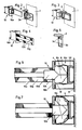
- the connecting part 10 can also be largely made of plastic and has a rod-shaped shaft 10g which, as shown in FIGS. 2 and 3, is inserted into the opening 2e of the holder. Before the connecting part 10 is pushed in, a shaft 3b of the latch 3 is partially inserted into the opening 2f of the holder 2. After the connecting part 10 has been inserted into the opening 2e, the bolt 3 in the holder 2 is moved downward, whereby corrugations 3a and 10h on the bolt 3 and on the connecting part 10 come into mutual engagement. As can be readily seen, the connecting part 10 can thereby be releasably fixed to the holder 2 practically continuously at any insertion depth. Accordingly, the desired distance of the mounting frame from the building wall 12 can be set and fixed.
- a holding member 10b which is shown in more detail in FIGS. 6 and 7, is arranged on the shaft 10g.
- This has a collar 10b which bears on the outside of the rail 4.
- a projection 10f molded onto it, which is inserted into the rail 4 and are accommodated in the two parts 10c held together by a resilient metal clip.
- these parts are brought into the spreading position shown in FIG. 7 with a wedge-shaped piece 10e.
- the piece 10e is pushed through an opening 10h in the collar 10b and through the slot 13 of the rail 4 into the extension 10f.
- the parts 10c are offset against the force of the clamp 8 transversely to the longitudinal direction of the rail 4 and lock the connecting part 10 in the rail 4.
- the connecting part 10 can thus be fixed at any point on the rail 4 without tools. Due to the lateral support of the parts 10c and the shoulder 10f on the inside of the rail 4, a stable attachment of the connecting part 10 to the rail 4 is achieved.
- the angular connecting parts 6 shown in FIGS. 8 and 9 are inserted into the brackets 2.
- These parts 6 each have corrugations 6d on a shaft 6c which correspond to the corrugations 10a of the connecting part 10.
- the connecting parts 6 can be inserted into the holder 2 and fixed in the desired insertion depth with the bolts 3.
- An arm 6a protruding at a right angle is formed on the shaft 6c with an opening 6d.
- a suitable one is used to fasten the connecting part 6 to the building wall 12 Pin or bolt inserted through the opening 6b in the building wall 12.
- the connecting part 6 is also preferably made of plastic.
Landscapes
- Health & Medical Sciences (AREA)
- Engineering & Computer Science (AREA)
- Public Health (AREA)
- Life Sciences & Earth Sciences (AREA)
- Hydrology & Water Resources (AREA)
- Water Supply & Treatment (AREA)
- Environmental & Geological Engineering (AREA)
- Connection Of Plates (AREA)
- Joining Of Building Structures In Genera (AREA)
- Mirrors, Picture Frames, Photograph Stands, And Related Fastening Devices (AREA)
- Audible-Bandwidth Dynamoelectric Transducers Other Than Pickups (AREA)
- Sanitary Device For Flush Toilet (AREA)
- Sink And Installation For Waste Water (AREA)
- Lining Or Joining Of Plastics Or The Like (AREA)
- Finishing Walls (AREA)
Priority Applications (1)
| Application Number | Priority Date | Filing Date | Title |
|---|---|---|---|
| AT90810505T ATE93561T1 (de) | 1989-07-07 | 1990-07-05 | Vorrichtung zur befestigung eines montagerahmens fuer sanitaerapparate. |
Applications Claiming Priority (2)
| Application Number | Priority Date | Filing Date | Title |
|---|---|---|---|
| CH255089 | 1989-07-07 | ||
| CH2550/89 | 1989-07-07 |
Publications (3)
| Publication Number | Publication Date |
|---|---|
| EP0407352A2 true EP0407352A2 (fr) | 1991-01-09 |
| EP0407352A3 EP0407352A3 (en) | 1991-03-20 |
| EP0407352B1 EP0407352B1 (fr) | 1993-08-25 |
Family
ID=4236316
Family Applications (1)
| Application Number | Title | Priority Date | Filing Date |
|---|---|---|---|
| EP90810505A Expired - Lifetime EP0407352B1 (fr) | 1989-07-07 | 1990-07-05 | Dispositif pour le raccordement d'un cadre pour un appareil sanitaire |
Country Status (7)
| Country | Link |
|---|---|
| US (1) | US5138802A (fr) |
| EP (1) | EP0407352B1 (fr) |
| JP (1) | JPH0366841A (fr) |
| AT (1) | ATE93561T1 (fr) |
| CA (1) | CA2018276A1 (fr) |
| DE (2) | DE8914495U1 (fr) |
| PT (1) | PT94590A (fr) |
Cited By (3)
| Publication number | Priority date | Publication date | Assignee | Title |
|---|---|---|---|---|
| EP0588766A1 (fr) * | 1992-09-14 | 1994-03-23 | Geberit AG | Container en particulier réservoir de chasse munie d'un élément de montage |
| EP2105544A1 (fr) * | 2008-03-27 | 2009-09-30 | Geberit Technik Ag | Elément ignifuge pour un dispositif sanitaire, dispositif sanitaire doté d'un tel élément ignifuge et ensemble d'extinction de feu pour un dispositif sanitaire |
| EP4352311A4 (fr) * | 2021-06-09 | 2025-04-09 | Eczacibasi Yapi Gerecleri Sanayi Ve Ticaret Anonim Sirketi | Système de réservoir de chasse d'eau dissimulé |
Families Citing this family (5)
| Publication number | Priority date | Publication date | Assignee | Title |
|---|---|---|---|---|
| US5718493A (en) * | 1995-04-04 | 1998-02-17 | Nikolai; Gerhard | Cabinet construction system |
| US6389772B2 (en) | 2000-04-19 | 2002-05-21 | William B. Gleckman | Universal building unit for building structures |
| PL203127B1 (pl) † | 2001-05-21 | 2009-08-31 | Geberit Technik Ag | Wspornik przyścienny ramy montażowej urządzeń sanitarnych |
| USD701173S1 (en) * | 2012-05-09 | 2014-03-18 | Brainwave Research Corporation | Electric device mounting bracket |
| USD711833S1 (en) * | 2012-05-10 | 2014-08-26 | Brainwave Research Corporation | Electric device mounting bracket |
Family Cites Families (12)
| Publication number | Priority date | Publication date | Assignee | Title |
|---|---|---|---|---|
| GB916805A (en) * | 1958-03-24 | 1963-01-30 | Warner & Sons Ltd S | Improvements in or relating to metal windows, curtain walling, partitions and the like |
| GB1417178A (en) * | 1972-12-13 | 1975-12-10 | Ickler O H | Apparatus for mounting facing panels in front of facades |
| FR2221608B3 (fr) * | 1973-03-15 | 1978-03-03 | Angers Grpt Interet Eco Ardois | |
| US4030261A (en) * | 1975-04-08 | 1977-06-21 | The Babcock & Wilcox Company | Ceramic cap for insulation anchor |
| FR2343870A2 (fr) * | 1976-03-08 | 1977-10-07 | Sadacem | Structure de mur-rideau |
| US4432182A (en) * | 1981-09-17 | 1984-02-21 | Armstrong World Industries, Inc. | Ceiling tile suspension system |
| DE3140861A1 (de) * | 1981-10-14 | 1983-04-21 | Hilti AG, 9494 Schaan | Verfahren, stuetzkoerper und duebel zur abstandsbefestigung von fassadenplatten bzw. fassadentraegern |
| US4519173A (en) * | 1982-06-07 | 1985-05-28 | Mercury Development Corp. | Slab-hanging system |
| FR2543192B1 (fr) * | 1983-03-23 | 1985-07-19 | Importation Diffusion Export S | Complexe d'isolation thermique par l'exterieur |
| CH667121A5 (de) * | 1985-03-08 | 1988-09-15 | Geberit Ag | Haltevorrichtung fuer die vorwandmontage von sanitaerapparaten, armaturen, rohrteilen und leitungen. |
| DE3517907A1 (de) * | 1985-05-17 | 1986-11-20 | Sanbloc GmbH Installations-Fertigbau, 8120 Weilheim | Wc-installationseinheit |
| DE3611072A1 (de) * | 1986-04-03 | 1987-10-08 | Siegfried Fricker | Vorrichtung zur verankerung von platten |
-
1989
- 1989-12-08 DE DE8914495U patent/DE8914495U1/de not_active Expired - Lifetime
-
1990
- 1990-06-05 CA CA002018276A patent/CA2018276A1/fr not_active Abandoned
- 1990-07-04 PT PT94590A patent/PT94590A/pt not_active Application Discontinuation
- 1990-07-05 DE DE90810505T patent/DE59002451D1/de not_active Expired - Fee Related
- 1990-07-05 JP JP2176508A patent/JPH0366841A/ja active Pending
- 1990-07-05 AT AT90810505T patent/ATE93561T1/de not_active IP Right Cessation
- 1990-07-05 EP EP90810505A patent/EP0407352B1/fr not_active Expired - Lifetime
- 1990-07-09 US US07/550,074 patent/US5138802A/en not_active Expired - Fee Related
Cited By (4)
| Publication number | Priority date | Publication date | Assignee | Title |
|---|---|---|---|---|
| EP0588766A1 (fr) * | 1992-09-14 | 1994-03-23 | Geberit AG | Container en particulier réservoir de chasse munie d'un élément de montage |
| US5396667A (en) * | 1992-09-14 | 1995-03-14 | Geberit Ag | Tank, in particular a flush tank, with a mounting element attached thereon |
| EP2105544A1 (fr) * | 2008-03-27 | 2009-09-30 | Geberit Technik Ag | Elément ignifuge pour un dispositif sanitaire, dispositif sanitaire doté d'un tel élément ignifuge et ensemble d'extinction de feu pour un dispositif sanitaire |
| EP4352311A4 (fr) * | 2021-06-09 | 2025-04-09 | Eczacibasi Yapi Gerecleri Sanayi Ve Ticaret Anonim Sirketi | Système de réservoir de chasse d'eau dissimulé |
Also Published As
| Publication number | Publication date |
|---|---|
| PT94590A (pt) | 1991-03-20 |
| CA2018276A1 (fr) | 1991-01-07 |
| JPH0366841A (ja) | 1991-03-22 |
| DE59002451D1 (de) | 1993-09-30 |
| EP0407352B1 (fr) | 1993-08-25 |
| EP0407352A3 (en) | 1991-03-20 |
| US5138802A (en) | 1992-08-18 |
| DE8914495U1 (de) | 1990-02-08 |
| ATE93561T1 (de) | 1993-09-15 |
Similar Documents
| Publication | Publication Date | Title |
|---|---|---|
| DE19511464A1 (de) | Vorrichtung zum Halten und Führen von Kabeln und Schläuchen in Schaltschränken | |
| DE69908576T2 (de) | Verbindungsvorrichtung | |
| WO2003050422A1 (fr) | Dispositif d'assemblage de jonction pour fixer des rails de montage | |
| EP0730081B1 (fr) | Dispositif de fixation pour le montage d'un élément décoratif, de protection solaire ou de protection contre la vue ou similaire | |
| EP0404726B1 (fr) | Dispositif pour la connexion de rails en forme de C, en particulier rails de montage | |
| EP0407352B1 (fr) | Dispositif pour le raccordement d'un cadre pour un appareil sanitaire | |
| DE9300178U1 (de) | Vorrichtung zur Kupplung von Stulpschienen | |
| EP0960983A2 (fr) | Dispositif pour le recouvrement d'un support mural | |
| DE102009050159A1 (de) | Montagevorrichtung für eine Einbauleuchte | |
| DE19707564A1 (de) | Montagesystem zur Halterung von Verkleidungselementen an Bauwerken | |
| EP0787909A1 (fr) | Dispositif de fixation pour profilés assemblés de façon télescopique | |
| DE19716165A1 (de) | Gerätehalterung, insbesondere für Wasser- oder Gaszähler | |
| EP3599338A1 (fr) | Dispositif de suspension permettant de fixer des stores | |
| CH650847A5 (en) | Mounting device for fastening on profiled rails having an essentially C-shaped cross-section | |
| EP0959536A1 (fr) | Bloc multiprises | |
| DE19853061C1 (de) | Wandkonsole für Heizkörper | |
| EP0271705A1 (fr) | Dispositif de fixation pour montage d'une cuvette de cuisine ou autre chose semblable | |
| DE102016108037A1 (de) | Befestigungsklammer | |
| DE19860743C1 (de) | Wandhalter für Verkleidungstafeln, insbesondere Fassadenelemente | |
| EP1531208B1 (fr) | Système de conduite pour l'évacuation d'un liquide | |
| DE29921834U1 (de) | Rohrhalterung für einen Dachrinnenentwässerungsrohrstrang | |
| DE3805257C2 (de) | Aufhängevorrichtung zum Befestigen einer Kabelmuffe an einem Tragseil | |
| DE19618515A1 (de) | Befestigungsvorrichtung | |
| EP1837446B1 (fr) | Structure de support sanitaire avec au moins un poteau et méthode de montage d'une structure de support | |
| DE102012004679A1 (de) | Befestigungseinrichtung zur Festlegung eines Heiz- oder Kühlkörpers |
Legal Events
| Date | Code | Title | Description |
|---|---|---|---|
| PUAI | Public reference made under article 153(3) epc to a published international application that has entered the european phase |
Free format text: ORIGINAL CODE: 0009012 |
|
| AK | Designated contracting states |
Kind code of ref document: A2 Designated state(s): AT BE CH DE DK ES FR GB IT LI NL |
|
| PUAL | Search report despatched |
Free format text: ORIGINAL CODE: 0009013 |
|
| AK | Designated contracting states |
Kind code of ref document: A3 Designated state(s): AT BE CH DE DK ES FR GB IT LI NL |
|
| 17P | Request for examination filed |
Effective date: 19910506 |
|
| 17Q | First examination report despatched |
Effective date: 19910920 |
|
| GRAA | (expected) grant |
Free format text: ORIGINAL CODE: 0009210 |
|
| AK | Designated contracting states |
Kind code of ref document: B1 Designated state(s): AT BE CH DE DK ES FR GB IT LI NL |
|
| PG25 | Lapsed in a contracting state [announced via postgrant information from national office to epo] |
Ref country code: GB Effective date: 19930825 Ref country code: ES Free format text: THE PATENT HAS BEEN ANNULLED BY A DECISION OF A NATIONAL AUTHORITY Effective date: 19930825 Ref country code: DK Effective date: 19930825 |
|
| REF | Corresponds to: |
Ref document number: 93561 Country of ref document: AT Date of ref document: 19930915 Kind code of ref document: T |
|
| ITF | It: translation for a ep patent filed | ||
| REF | Corresponds to: |
Ref document number: 59002451 Country of ref document: DE Date of ref document: 19930930 |
|
| ET | Fr: translation filed | ||
| GBV | Gb: ep patent (uk) treated as always having been void in accordance with gb section 77(7)/1977 [no translation filed] |
Effective date: 19930825 |
|
| PLBE | No opposition filed within time limit |
Free format text: ORIGINAL CODE: 0009261 |
|
| STAA | Information on the status of an ep patent application or granted ep patent |
Free format text: STATUS: NO OPPOSITION FILED WITHIN TIME LIMIT |
|
| PG25 | Lapsed in a contracting state [announced via postgrant information from national office to epo] |
Ref country code: BE Effective date: 19940731 |
|
| 26N | No opposition filed | ||
| BERE | Be: lapsed |
Owner name: GEBERIT A.G. Effective date: 19940731 |
|
| PG25 | Lapsed in a contracting state [announced via postgrant information from national office to epo] |
Ref country code: FR Effective date: 19950331 |
|
| REG | Reference to a national code |
Ref country code: FR Ref legal event code: ST |
|
| REG | Reference to a national code |
Ref country code: CH Ref legal event code: PUE Owner name: GEBERIT PRODUKTIONS AG TRANSFER- GEBERIT TECHNIK A Ref country code: CH Ref legal event code: PFA Free format text: GEBERIT AG TRANSFER- GEBERIT PRODUKTIONS AG |
|
| NLS | Nl: assignments of ep-patents |
Owner name: GEBERIT TECHNIK AG |
|
| NLT1 | Nl: modifications of names registered in virtue of documents presented to the patent office pursuant to art. 16 a, paragraph 1 |
Owner name: GEBERIT PRODUKTIONS AG |
|
| PGFP | Annual fee paid to national office [announced via postgrant information from national office to epo] |
Ref country code: CH Payment date: 20010518 Year of fee payment: 12 |
|
| PG25 | Lapsed in a contracting state [announced via postgrant information from national office to epo] |
Ref country code: LI Free format text: LAPSE BECAUSE OF NON-PAYMENT OF DUE FEES Effective date: 20020731 Ref country code: CH Free format text: LAPSE BECAUSE OF NON-PAYMENT OF DUE FEES Effective date: 20020731 |
|
| REG | Reference to a national code |
Ref country code: CH Ref legal event code: PL |
|
| PGFP | Annual fee paid to national office [announced via postgrant information from national office to epo] |
Ref country code: NL Payment date: 20030619 Year of fee payment: 14 |
|
| PGFP | Annual fee paid to national office [announced via postgrant information from national office to epo] |
Ref country code: DE Payment date: 20030625 Year of fee payment: 14 |
|
| PGFP | Annual fee paid to national office [announced via postgrant information from national office to epo] |
Ref country code: AT Payment date: 20040608 Year of fee payment: 15 |
|
| PG25 | Lapsed in a contracting state [announced via postgrant information from national office to epo] |
Ref country code: NL Free format text: LAPSE BECAUSE OF NON-PAYMENT OF DUE FEES Effective date: 20050201 Ref country code: DE Free format text: LAPSE BECAUSE OF NON-PAYMENT OF DUE FEES Effective date: 20050201 |
|
| NLV4 | Nl: lapsed or anulled due to non-payment of the annual fee |
Effective date: 20050201 |
|
| PG25 | Lapsed in a contracting state [announced via postgrant information from national office to epo] |
Ref country code: IT Free format text: LAPSE BECAUSE OF NON-PAYMENT OF DUE FEES;WARNING: LAPSES OF ITALIAN PATENTS WITH EFFECTIVE DATE BEFORE 2007 MAY HAVE OCCURRED AT ANY TIME BEFORE 2007. THE CORRECT EFFECTIVE DATE MAY BE DIFFERENT FROM THE ONE RECORDED. Effective date: 20050705 Ref country code: AT Free format text: LAPSE BECAUSE OF NON-PAYMENT OF DUE FEES Effective date: 20050705 |