EP0407730A2 - Foyer, notamment foyer à lit fluidisÀ© - Google Patents
Foyer, notamment foyer à lit fluidisÀ© Download PDFInfo
- Publication number
- EP0407730A2 EP0407730A2 EP90110535A EP90110535A EP0407730A2 EP 0407730 A2 EP0407730 A2 EP 0407730A2 EP 90110535 A EP90110535 A EP 90110535A EP 90110535 A EP90110535 A EP 90110535A EP 0407730 A2 EP0407730 A2 EP 0407730A2
- Authority
- EP
- European Patent Office
- Prior art keywords
- train
- furnace according
- gas
- combustion chamber
- fluidized bed
- Prior art date
- Legal status (The legal status is an assumption and is not a legal conclusion. Google has not performed a legal analysis and makes no representation as to the accuracy of the status listed.)
- Granted
Links
Images

Classifications
-
- F—MECHANICAL ENGINEERING; LIGHTING; HEATING; WEAPONS; BLASTING
- F23—COMBUSTION APPARATUS; COMBUSTION PROCESSES
- F23C—METHODS OR APPARATUS FOR COMBUSTION USING FLUID FUEL OR SOLID FUEL SUSPENDED IN A CARRIER GAS OR AIR
- F23C10/00—Fluidised bed combustion apparatus
- F23C10/16—Fluidised bed combustion apparatus specially adapted for operation at superatmospheric pressures, e.g. by the arrangement of the combustion chamber and its auxiliary systems inside a pressure vessel
-
- B—PERFORMING OPERATIONS; TRANSPORTING
- B01—PHYSICAL OR CHEMICAL PROCESSES OR APPARATUS IN GENERAL
- B01J—CHEMICAL OR PHYSICAL PROCESSES, e.g. CATALYSIS OR COLLOID CHEMISTRY; THEIR RELEVANT APPARATUS
- B01J8/00—Chemical or physical processes in general, conducted in the presence of fluids and solid particles; Apparatus for such processes
- B01J8/18—Chemical or physical processes in general, conducted in the presence of fluids and solid particles; Apparatus for such processes with fluidised particles
- B01J8/24—Chemical or physical processes in general, conducted in the presence of fluids and solid particles; Apparatus for such processes with fluidised particles according to "fluidised-bed" technique
- B01J8/38—Chemical or physical processes in general, conducted in the presence of fluids and solid particles; Apparatus for such processes with fluidised particles according to "fluidised-bed" technique with fluidised bed containing a rotatable device or being subject to rotation or to a circulatory movement, i.e. leaving a vessel and subsequently re-entering it
- B01J8/384—Chemical or physical processes in general, conducted in the presence of fluids and solid particles; Apparatus for such processes with fluidised particles according to "fluidised-bed" technique with fluidised bed containing a rotatable device or being subject to rotation or to a circulatory movement, i.e. leaving a vessel and subsequently re-entering it being subject to a circulatory movement only
- B01J8/388—Chemical or physical processes in general, conducted in the presence of fluids and solid particles; Apparatus for such processes with fluidised particles according to "fluidised-bed" technique with fluidised bed containing a rotatable device or being subject to rotation or to a circulatory movement, i.e. leaving a vessel and subsequently re-entering it being subject to a circulatory movement only externally, i.e. the particles leaving the vessel and subsequently re-entering it
-
- F—MECHANICAL ENGINEERING; LIGHTING; HEATING; WEAPONS; BLASTING
- F22—STEAM GENERATION
- F22B—METHODS OF STEAM GENERATION; STEAM BOILERS
- F22B31/00—Modifications of boiler construction, or of tube systems, dependent on installation of combustion apparatus; Arrangements or dispositions of combustion apparatus
- F22B31/0007—Modifications of boiler construction, or of tube systems, dependent on installation of combustion apparatus; Arrangements or dispositions of combustion apparatus with combustion in a fluidized bed
- F22B31/0084—Modifications of boiler construction, or of tube systems, dependent on installation of combustion apparatus; Arrangements or dispositions of combustion apparatus with combustion in a fluidized bed with recirculation of separated solids or with cooling of the bed particles outside the combustion bed
-
- F—MECHANICAL ENGINEERING; LIGHTING; HEATING; WEAPONS; BLASTING
- F23—COMBUSTION APPARATUS; COMBUSTION PROCESSES
- F23C—METHODS OR APPARATUS FOR COMBUSTION USING FLUID FUEL OR SOLID FUEL SUSPENDED IN A CARRIER GAS OR AIR
- F23C10/00—Fluidised bed combustion apparatus
- F23C10/02—Fluidised bed combustion apparatus with means specially adapted for achieving or promoting a circulating movement of particles within the bed or for a recirculation of particles entrained from the bed
- F23C10/04—Fluidised bed combustion apparatus with means specially adapted for achieving or promoting a circulating movement of particles within the bed or for a recirculation of particles entrained from the bed the particles being circulated to a section, e.g. a heat-exchange section or a return duct, at least partially shielded from the combustion zone, before being reintroduced into the combustion zone
- F23C10/08—Fluidised bed combustion apparatus with means specially adapted for achieving or promoting a circulating movement of particles within the bed or for a recirculation of particles entrained from the bed the particles being circulated to a section, e.g. a heat-exchange section or a return duct, at least partially shielded from the combustion zone, before being reintroduced into the combustion zone characterised by the arrangement of separation apparatus, e.g. cyclones, for separating particles from the flue gases
- F23C10/10—Fluidised bed combustion apparatus with means specially adapted for achieving or promoting a circulating movement of particles within the bed or for a recirculation of particles entrained from the bed the particles being circulated to a section, e.g. a heat-exchange section or a return duct, at least partially shielded from the combustion zone, before being reintroduced into the combustion zone characterised by the arrangement of separation apparatus, e.g. cyclones, for separating particles from the flue gases the separation apparatus being located outside the combustion chamber
-
- F—MECHANICAL ENGINEERING; LIGHTING; HEATING; WEAPONS; BLASTING
- F23—COMBUSTION APPARATUS; COMBUSTION PROCESSES
- F23C—METHODS OR APPARATUS FOR COMBUSTION USING FLUID FUEL OR SOLID FUEL SUSPENDED IN A CARRIER GAS OR AIR
- F23C2206/00—Fluidised bed combustion
- F23C2206/10—Circulating fluidised bed
- F23C2206/103—Cooling recirculating particles
Definitions
- the invention relates to a furnace, in particular a fluidized bed furnace with the features of the preamble of claim 1.
- the solid In a known fluidized bed furnace provided with a circulating fluidized bed (EP-PS 103 613), the solid is separated from the flue gas by means of a swirl separator, collected in a collecting bunker and from there returned to the fluidized bed.
- the separated solid is not significantly cooled before it is returned to the fluidized bed, since the collecting bunker contains no heating surfaces with the exception of the walls formed from the tube walls and because the solid is only fluidized with so much air that even conveying is achieved.
- circulating fluidized bed furnace In another known circulating fluidized bed furnace (DE-PS 26 24 302) the solid is circulated through a circulation system consisting of a fluidized bed reactor, cyclone separator and return line with a high suspension density in the flue gas and at a constant system temperature. Part of the solids is removed from this circuit, cooled in a separate fluidized bed cooler provided with heating surfaces and through which air flows, and returned at least as a partial stream to the fluidized bed furnace.
- a fluidized bed combustion with a fluidized bed and an increased solids circulation is also known (BWK 40 (1988), pages 273 to 276), in which bundle heating surfaces for cooling flue gas and airborne dust are arranged in the space above the fluidized bed.
- Immersion heating surfaces are arranged in the stationary fluidized bed of another known fluidized bed furnace (VGB Kraftwerkstechnik 67 (1987), number 8, pages 571 to 577).
- the fluidized bed combustion is operated under pressure, the fluidized bed combustion chamber being surrounded by a pressure vessel. That means the Flue gas leaving the vortex combustion chamber is fed to a gas turbine.
- immersion heating surfaces are not arranged in the fluidized bed combustion chamber. Instead, the vortex combustion chamber is provided with wall and / or bulkhead heating surfaces, which are flown over by the flue gas, which is heavily laden with dust. For a given output, the amount of gas generated is also given.
- the flow cross sections cannot be increased arbitrarily for design reasons. This results in certain minimum gas velocities that cannot be undercut. The dust-laden gas flowing at these speeds leads to erosions on the wall and bulkhead heating surfaces.
- Fluidized bed furnaces operated under pressure with a stationary fluidized bed are regulated by reducing the bed height as the load decreases. With a reduced bed height, the protrude Immersion heating surfaces partly out of the fluidized bed so that less heat is removed from the fluidized bed. At the same time, the gas temperature drops, as a result of which gas is fed to the downstream gas turbine at a temperature which is dependent on the load.
- the invention has for its object to design the generic firing so that the disadvantages with regard to the design of the reaction chamber and the erosion and corrosion on the heating surfaces are avoided, that the geometric dimensions of the firing largely largely freely selectable, especially with respect to the ratio of reactor cross section to reactor height and that the gas temperature is independent of the load.
- the volume-related processes of heat release in a reaction zone, the after-reaction in an after-combustion zone and the flue gas cleaning and heat dissipation in a solid cooling zone separated from each other can thus be varied without having an effect on the overall process.
- the height and the cross section of the section of the furnace assigned to one of these processes can thus be freely selected. It is thus possible to reduce the gas velocity in the section which contains heating surfaces at risk of erosion to such an extent that these heating surfaces are not subject to any significant attack by erosion.
- the solid that collects in the cooling zone in the second pass has a small grain size due to a sighting in the combustion chamber. Even low gas velocities are sufficient to fluidize this solid.
- the high heat transfer coefficient caused by the fluidization enables small Use heating surfaces. Since there is no reducing gas atmosphere in the cooling zone, highly resilient heating surfaces made of austenitic materials can also be used here.
- the heating surfaces at risk of erosion can be removed from the section in which high gas velocities are to be set.
- the dwell time necessary for the burnout of the fuel can be optimally adjusted by the freely selectable ratio of cross-section to the height of the furnace and thus by the gas velocity, so that coal with a wide grain spectrum can be fed in if the burnout is good.
- the swirl temperature and thus the gas temperature can be set for all load conditions by removing the heat from the separated solid in the cooling zone and choosing the excess air in the reaction zone.
- the gas temperature at the end of the afterburning zone can be raised to values which are above the temperature required for the operation of a fluidized bed.
- the amount of the solid returned to the reaction zone is freely selectable, since the solid can be cooled to an adjustable temperature in the cooling zone.
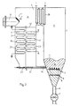
- the furnace is flowed through from bottom to top Combustion chamber 1 carried out, which is followed by a second train 2 via a transverse train 5.
- the combustion chamber 1 and the second train 2 are delimited by walls, preferably by tube walls made of tubes which are welded together in a gastight manner.
- a solid, liquid or gaseous fuel and combustion air are supplied via feeds, not shown.
- the furnace can be a fluidized bed firing with a stationary or a circulating fluidized bed or a transport reactor with entrained-flow combustion.
- This furnace represents a reaction zone R, which is followed by an afterburning zone A, which ends in front of a separator 10, which is located in the flow direction of the gas behind the connection of the combustion chamber 1 with the second train 2.
- the post-combustion zone A is supplied with additional combustion air and, if appropriate, additional fuel.
- a cooling zone C is formed within the second train 2.
- the invention is explained below using the example of a furnace designed as a fluidized bed furnace.
- This furnace comprises a fluidized bed with an increased solids circulation.
- the following description also applies analogously to a highly circulating fluidized bed or dust firing with solids recirculation.
- a nozzle base 3 is arranged, through which air is blown in as combustion air and as fluidizing air.
- the air is introduced at such a speed and in such an amount that a fluidized bed 4 preferably with a defined bed surface forms above the nozzle base 3.
- the fluidized bed 4 represents the reaction zone R.
- the combustion chamber 1 is provided with an ash discharge 6, in which a discharge element 7, for example a cellular wheel sluice, is arranged.
- a resting ash layer 8 is located between the nozzle base 3 and the discharge element 7.
- Nozzles 9 are arranged within the resting ash layer 8.
- a gaseous medium for example air or flue gas, is blown through these nozzles to cool the ash layer 8. The gas comes together with the fluidizing air from the nozzle base 3 into the combustion chamber 1.
- a flow of flue gas and entrained solid particles is set up in the combustion chamber 1.
- a separator 10 is arranged behind the connection of the combustion chamber 1 and the second train 2.
- the gas-side discharge of the separator 10 is connected to a gas discharge line 11.
- the gas discharge line 11 is connected to a system for further treatment of the flue gas.
- This further treatment plant can be either a waste heat boiler or a gas turbine if the fluidized bed combustion, as will be described below, under an overpressure of e.g. 20 bar is operated.
- the separator 10 which is only shown schematically in FIGS. 1 and 2, is designed as a filtering separator, the solids discharge of which protrudes into the second train 2.
- Such separators are known for cleaning flue gas from fluidized bed furnaces (VDI report No. 715 (1989) pp. 289-322, esp. Pp. 299-309, 315-317) and are characterized by a high degree of separation.
- a packed bed filter can be used as the separator, which comprises a perforated, inclined bottom on which a filter layer made of a granular filter material, e.g. Quartz sand.
- Bed material from the fluidized bed 4 can also be used as the filter material. The dust deposited on the filter layer when the flue gas passes through is blown off from time to time and reaches the second train 2, in which a solid layer 12 is formed in this way.
- a candle filter is preferably used.
- a filter is shown in Fig. 3 and consists of filter tubes 13 made of porous, ceramic material.
- the filter tubes 13 are fastened in a holding device in the second train 2.
- the solids-laden gas flows through the porous filter material in order to get to the clean gas side and into the gas discharge line 11.
- the Solid is separated on the gas side of the filter tubes 13. The deposit that forms falls out of its own accord or during backwashing in the second pass 2 and thus forms the solid layer 12.
- the second train 2 is connected at the lower end via a solids return line 14 to the combustion chamber 1 above the nozzle base 3.
- a nozzle grate 15 is arranged, through which air is blown through the solid layer 12.
- another gas e.g. recirculated flue gas can be used. After flowing through the solid layer 12, this air or this gas is discharged together with the flue gas from the combustion chamber 1 through the separator 10 and the gas discharge pipe 11.
- the air can also be used as secondary combustion air, e.g. be blown into the afterburning zone A using an ejector.
- Heating surfaces 16, 17 are arranged within the solid layer 12 of the second train 2.
- a liquid or gaseous heat exchange medium such as gas, air, steam, water, thermal oil or liquid metal flows through these heating surfaces 16, 17.
- the heating surfaces can be connected to a water-steam circuit together with the tube walls of the second train 2 and the combustion chamber 1.
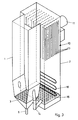
- the second train 2 can be divided into two or more superimposed chambers 19, 20 by inserting further nozzle grids 18.
- the second train 2 can be divided into a plurality of adjacent chambers 21, 22 by one or more vertical, uncooled or partition walls formed from tubes welded to one another in a gastight manner.
- Each of these adjacent chambers is provided with its own nozzle grate 23, 24.
- the nozzle gratings 23, 24 can therefore be acted upon with different volume flows.
- Each chamber 19, 20, 21, 22 also has its own heating surface 16, 17 which can be connected in different ways, for example as an economizer, evaporator or superheater of a water-steam cycle.
- the solid of the solid layer 12 within the second train 2 is cooled by giving off heat to the blown air or to the blown gas and to the heat exchange medium flowing through the heating surfaces 16, 17.
- the solid separated in the separator 10 and cooled in the second train 2 is completely or partially returned to the combustion chamber 1 via the solids return line 14.
- the temperature in the combustion chamber 1 is thereby kept constant at 750 to 900 degrees C, preferably at 850 degrees C, since the combustion heat released during the combustion of the fuel with air is transferred to the heat exchange medium in the tube walls delimiting the combustion chamber 1 and to the recirculated, cooled ones Solid is discharged.
- the flue gas enters the separator 10 at the temperature of the fluidized bed. It is also possible to carry out incomplete combustion in the combustion chamber 1 by air deficiency, so that the gas emerging from the fluidized bed 4 still contains combustible constituents. These combustible components are re-burned in afterburning zone A. In this way the temperature of the flue gas emerging from the gas discharge line 11 can be raised to a temperature above the bed temperature, e.g. be raised to 1000 degrees C.
- the air flowing through the solid layer 12 serves as combustion air for the afterburning zone A. Separate secondary and tertiary combustion air can optionally be blown into the afterburning zone A together with additional fuel. Such a procedure is advantageous if the fluidized bed combustion is operated under excess pressure.
- a fixed bed is formed at gas velocities below the fluidization point and a fluidized bed at gas velocities above the fluidization point. Since the heat transfer coefficient in the fluidized bed is significantly greater than in the fixed bed, the distribution of the heat extracted from the solid to the air and the heat exchange medium can be changed by changing the speed in the vicinity of the fluidization point of the air flowing through the solid layer 12 be influenced in the heating surfaces 16, 17. In order to transfer the heat preferentially to air or the gas, a fixed bed is desirable. If the heat is to be increasingly transferred to the heat exchange medium in the heating surfaces 16, 17, the solid layer 12 is to be fluidized. This influence on the distribution of heat dissipation can be achieved in a favorable manner in the described division of the second train 2 into several chambers 19, 20, 21, 22. It is also possible to maintain a fixed bed in one chamber and a fluidized bed in another chamber.
- heating surfaces 29 touched by the flue gas can be arranged behind the reaction zone R between the combustion chamber 1 and the second train 2, that is to say in the afterburning zone A, in the flow direction of the flue gas.
- a corresponding cross-sectional design ensures that the gas velocity does not become too high at this point.
- the furnace described can be operated at a pressure slightly exceeding the atmospheric pressure in order to be able to dispense with an induced draft.
- An overpressure of more than 1 bar to 30 bar, preferably 20 bar, can also be set in the combustion chamber 1 and the second train 2.
- the cleaned gas entering the gas discharge line 11 can be expanded in a gas turbine or fed to a chemical process.
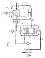
- FIG. 4 A particular furnace operated under positive pressure is shown in FIG. 4.
- the combustion chamber 1 and the second train 2 are arranged in separate pressure vessels 26, 27.
- a pressure line 28, which penetrates the pressure vessels 26, 27, connects the combustion chamber 1 to the second train 2.
- the gas discharge line 11 is connected to a gas turbine 25.
- the combustion chamber 1 and the second train 2 can also be enclosed by a common pressure vessel.
- the embodiment operated under pressure according to FIG. 4 corresponds to the fluidized bed firing operated under atmospheric pressure or under pressure according to FIGS. 1 to 3 in the basic principle.
Landscapes
- Engineering & Computer Science (AREA)
- Chemical & Material Sciences (AREA)
- Combustion & Propulsion (AREA)
- Mechanical Engineering (AREA)
- General Engineering & Computer Science (AREA)
- Thermal Sciences (AREA)
- Physics & Mathematics (AREA)
- Organic Chemistry (AREA)
- Chemical Kinetics & Catalysis (AREA)
- Fluidized-Bed Combustion And Resonant Combustion (AREA)
- Industrial Gases (AREA)
- Emergency Alarm Devices (AREA)
- Processing Of Solid Wastes (AREA)
- Crucibles And Fluidized-Bed Furnaces (AREA)
- Preparation Of Clay, And Manufacture Of Mixtures Containing Clay Or Cement (AREA)
Priority Applications (1)
| Application Number | Priority Date | Filing Date | Title |
|---|---|---|---|
| AT90110535T ATE96895T1 (de) | 1989-07-11 | 1990-06-02 | Feuerung insbesondere wirbelschichtfeuerung. |
Applications Claiming Priority (2)
| Application Number | Priority Date | Filing Date | Title |
|---|---|---|---|
| DE3922765 | 1989-07-11 | ||
| DE3922765A DE3922765A1 (de) | 1989-07-11 | 1989-07-11 | Feuerung, insbesondere wirbelschichtfeuerung |
Publications (3)
| Publication Number | Publication Date |
|---|---|
| EP0407730A2 true EP0407730A2 (fr) | 1991-01-16 |
| EP0407730A3 EP0407730A3 (en) | 1991-03-20 |
| EP0407730B1 EP0407730B1 (fr) | 1993-11-03 |
Family
ID=6384731
Family Applications (1)
| Application Number | Title | Priority Date | Filing Date |
|---|---|---|---|
| EP90110535A Expired - Lifetime EP0407730B1 (fr) | 1989-07-11 | 1990-06-02 | Foyer, notamment foyer à lit fluidisé |
Country Status (7)
| Country | Link |
|---|---|
| US (1) | US5054435A (fr) |
| EP (1) | EP0407730B1 (fr) |
| JP (1) | JP2969369B2 (fr) |
| AT (1) | ATE96895T1 (fr) |
| DD (1) | DD296542A5 (fr) |
| DE (2) | DE3922765A1 (fr) |
| ES (1) | ES2045648T3 (fr) |
Cited By (3)
| Publication number | Priority date | Publication date | Assignee | Title |
|---|---|---|---|---|
| EP0515878A3 (en) * | 1991-05-31 | 1993-04-21 | A. Ahlstrom Corporation | Cleaning of high temperature high pressure (hthp) gases |
| EP0550923A1 (fr) * | 1992-01-08 | 1993-07-14 | METALLGESELLSCHAFT Aktiengesellschaft | Procédé et appareil pour le refroidissement de matières solides chaudes d'un réacteur à lit fluidisé |
| EP0784186A1 (fr) * | 1996-01-13 | 1997-07-16 | LLB Lurgi Lentjes Babcock Energietechnik GmbH | Générateur de vapeur avec combustion sous pression en lit fluidisé circulant |
Families Citing this family (10)
| Publication number | Priority date | Publication date | Assignee | Title |
|---|---|---|---|---|
| ES2050059B1 (es) * | 1991-07-03 | 1996-07-16 | Babcock & Wilcox Espanola | Instalacion perfeccionada para la generacion de energia electrica por combustion en lecho fluido a presion. |
| DE4141227C2 (de) * | 1991-12-13 | 2002-06-27 | Babcock Energie Umwelt | Wirbelschichtreaktor |
| DE4310952A1 (de) * | 1993-04-02 | 1994-10-06 | Adolf Schmidt | Verfeuerungsverfahren |
| US6010821A (en) | 1997-05-23 | 2000-01-04 | Minnesota Mining And Manufacturing Company | Aqueous developable color proofing elements |
| US5938697A (en) * | 1998-03-04 | 1999-08-17 | Scimed Life Systems, Inc. | Stent having variable properties |
| FR2803020B1 (fr) * | 1999-12-22 | 2002-04-12 | Abb Alstom Power Comb | Procede pour reduire les emissions d'oxydes d'azote dans une installation de combustion en lit fluidise circulant |
| DE102008028600A1 (de) * | 2008-06-18 | 2009-12-31 | Gea Brewery Systems Gmbh | Sudhausanlage mit Filtrationseinrichtung und Verfahren zur thermischen Verwertung von feuchten Filtrationspartikeln |
| US20100169044A1 (en) * | 2008-12-18 | 2010-07-01 | Benefiel John R | Method of Determining Weight Of Segments Of An Item |
| US8308836B2 (en) * | 2009-04-20 | 2012-11-13 | Southern Company | Continuous coarse ash depressurization system |
| FI129147B (en) * | 2017-12-19 | 2021-08-13 | Valmet Technologies Oy | Fluidized bed boiler with gas lock heat exchanger |
Family Cites Families (23)
| Publication number | Priority date | Publication date | Assignee | Title |
|---|---|---|---|---|
| US2818049A (en) * | 1954-08-05 | 1957-12-31 | Combustion Eng | Method of heating |
| US4286548A (en) * | 1979-11-19 | 1981-09-01 | Brash Leslie O | Gas recirculation apparatus with integral ash hoppers |
| US4419965A (en) * | 1981-11-16 | 1983-12-13 | Foster Wheeler Energy Corporation | Fluidized reinjection of carryover in a fluidized bed combustor |
| FI66297C (fi) * | 1982-11-15 | 1984-10-10 | Ahlstroem Oy | Anordning foer avlaegsnande av fasta komponenter ur roekgaser |
| DE3338107A1 (de) * | 1982-11-30 | 1984-05-30 | BBC Aktiengesellschaft Brown, Boveri & Cie., Baden, Aargau | Kohlegefeuertes kraftwerk mit wirbelschichtfeuerung |
| GB8327074D0 (en) * | 1983-10-10 | 1983-11-09 | English Electric Co Ltd | Fluidised-bed heat and power plant |
| US4672918A (en) * | 1984-05-25 | 1987-06-16 | A. Ahlstrom Corporation | Circulating fluidized bed reactor temperature control |
| DE3440583A1 (de) * | 1984-11-07 | 1986-05-07 | Buderus Ag, 6330 Wetzlar | Dampf- oder heisswassererzeuger |
| US4809623A (en) * | 1985-08-07 | 1989-03-07 | Foster Wheeler Energy Corporation | Fluidized bed reactor and method of operating same |
| FI853464A0 (fi) * | 1985-09-11 | 1985-09-11 | Ahlstroem Oy | Reaktor med cirkulerande baedd. |
| SE451628B (sv) * | 1986-02-21 | 1987-10-19 | Asea Stal Ab | Kraftanleggning med fluidiserad bedd och renare av centrifugaltyp for forbrenningsgaser |
| US4640201A (en) * | 1986-04-30 | 1987-02-03 | Combustion Engineering, Inc. | Fluidized bed combustor having integral solids separator |
| US4682567A (en) * | 1986-05-19 | 1987-07-28 | Foster Wheeler Energy Corporation | Fluidized bed steam generator and method of generating steam including a separate recycle bed |
| SE460146B (sv) * | 1986-08-14 | 1989-09-11 | Goetaverken Energy Syst Ab | Anordning vid foerbraenningsanlaeggning med cirkulerande fluidbaedd |
| US4712514A (en) * | 1986-09-05 | 1987-12-15 | Qinghua University | Fluidized bed boiler and high temperature separators used therein |
| SE459986B (sv) * | 1987-04-09 | 1989-08-28 | Asea Stal Ab | Kraftanlaeggning med cyklonrenare med kylda cyklonben |
| DE3715516A1 (de) * | 1987-05-09 | 1988-11-17 | Inter Power Technologie | Wirbelschichtfeuerung |
| US4869207A (en) * | 1987-07-13 | 1989-09-26 | A. Ahlstrom Corporation | Circulating fluidized bed reactor |
| FI873735A0 (fi) * | 1987-08-28 | 1987-08-28 | Ahlstroem Oy | Foerfarande och anordning foer foergasning av fast kolhaltigt material. |
| DK633488D0 (da) * | 1988-11-11 | 1988-11-11 | Risoe Forskningscenter | Reaktor |
| US4899695A (en) * | 1989-02-14 | 1990-02-13 | Air Products And Chemicals, Inc. | Fluidized bed combustion heat transfer enhancement |
| US4951611A (en) * | 1989-06-09 | 1990-08-28 | Foster Wheeler Energy Corporation | Fluidized bed reactor utilizing an internal solids separator |
| US4955295A (en) * | 1989-08-18 | 1990-09-11 | Foster Wheeler Energy Corporation | Method and system for controlling the backflow sealing efficiency and recycle rate in fluidized bed reactors |
-
1989
- 1989-07-11 DE DE3922765A patent/DE3922765A1/de not_active Withdrawn
-
1990
- 1990-06-02 ES ES90110535T patent/ES2045648T3/es not_active Expired - Lifetime
- 1990-06-02 DE DE90110535T patent/DE59003303D1/de not_active Expired - Fee Related
- 1990-06-02 EP EP90110535A patent/EP0407730B1/fr not_active Expired - Lifetime
- 1990-06-02 AT AT90110535T patent/ATE96895T1/de active
- 1990-07-05 JP JP2178496A patent/JP2969369B2/ja not_active Expired - Fee Related
- 1990-07-10 DD DD90342658A patent/DD296542A5/de not_active IP Right Cessation
- 1990-07-10 US US07/550,463 patent/US5054435A/en not_active Expired - Lifetime
Cited By (4)
| Publication number | Priority date | Publication date | Assignee | Title |
|---|---|---|---|---|
| EP0515878A3 (en) * | 1991-05-31 | 1993-04-21 | A. Ahlstrom Corporation | Cleaning of high temperature high pressure (hthp) gases |
| EP0550923A1 (fr) * | 1992-01-08 | 1993-07-14 | METALLGESELLSCHAFT Aktiengesellschaft | Procédé et appareil pour le refroidissement de matières solides chaudes d'un réacteur à lit fluidisé |
| US5308585A (en) * | 1992-01-08 | 1994-05-03 | Metallgesellschaft Aktiengesellschaft | Process and apparatus for cooling hot solids coming from a fluidized bed reactor |
| EP0784186A1 (fr) * | 1996-01-13 | 1997-07-16 | LLB Lurgi Lentjes Babcock Energietechnik GmbH | Générateur de vapeur avec combustion sous pression en lit fluidisé circulant |
Also Published As
| Publication number | Publication date |
|---|---|
| US5054435A (en) | 1991-10-08 |
| JP2969369B2 (ja) | 1999-11-02 |
| JPH0391602A (ja) | 1991-04-17 |
| DE59003303D1 (de) | 1993-12-09 |
| EP0407730A3 (en) | 1991-03-20 |
| ES2045648T3 (es) | 1994-01-16 |
| EP0407730B1 (fr) | 1993-11-03 |
| DE3922765A1 (de) | 1991-01-17 |
| DD296542A5 (de) | 1991-12-05 |
| ATE96895T1 (de) | 1993-11-15 |
Similar Documents
| Publication | Publication Date | Title |
|---|---|---|
| AT401418B (de) | Verfahren und vorrichtung zur steuerung der funktion eines wirbelschichtreaktors mit zirkulierender wirbelschicht | |
| DE2624302C2 (de) | Verfahren zur Durchführung exothermer Prozesse | |
| EP0206066B1 (fr) | Dispositif de combustion à lit fluidisé circulant | |
| DE69330182T2 (de) | Heissgasfilter | |
| EP0281165B1 (fr) | Installation à lit fluidisé | |
| DE69514170T2 (de) | Wirbelschichtfeuerungsanlage und Verfahren mit einem Mehrkammerrezirkulationswärmetauscher mit veränderlicher Leistung | |
| EP0407730B1 (fr) | Foyer, notamment foyer à lit fluidisé | |
| DE3625992C2 (fr) | ||
| DE69519891T2 (de) | Druckwirbelschicht-Feuerung mit integriertem Rezirkulationswärmetauscher | |
| DE2539546A1 (de) | Verfahren zur verbrennung kohlenstoffhaltiger materialien | |
| DE3640377A1 (de) | Verfahren zur verbrennung von kohlenstoffhaltigen materialien in einem wirbelschichtreaktor und vorrichtung zur durchfuehrung des verfahrens | |
| EP0152529A2 (fr) | Générateur de vapeur avec combustion en lit fluidisé stationnaire | |
| EP0748647A1 (fr) | Procédé et dispositif pour réduire la teneur en poussière d'un gaz provenant de la combustion d'un générateur de vapeur | |
| EP0903536A1 (fr) | Générateur de vapeur avec séparateur de poussière intégré | |
| DE69628280T2 (de) | Wirbelbettanordnung mit durchflussausgleich | |
| EP0186756B1 (fr) | Combustion en lit fluidisé avec des surfaces de chauffe immergées | |
| EP0181626B1 (fr) | Installation de génération de vapeur pour chambre de combustion à plusieurs lits fluidisés et procédé de son contrôle et sa régulation | |
| DE2804073C2 (de) | Wirbelschicht-Verbrennungsvorrichtung | |
| DE3644083A1 (de) | Dampferzeuger | |
| DE69526968T2 (de) | Abtrennung von teilchen aus rauchgasen bei der verbrennung und vergasung fossiler brennstoffe | |
| DE69223415T2 (de) | Verfahren und vorrichtung zur kühlung der in einem wirbelbettkessel zirkulierenden stoffe | |
| DE3519159A1 (de) | Wasserrohr - dampferzeuger bzw. wasserrohr - heisswassererzeuger | |
| DE4336100C1 (de) | Vorrichtung zur Abscheidung flüssiger Asche | |
| DE3544425A1 (de) | Verfahren zum verbrennen von festen brennstoffen in einer zirkulierenden wirbelschicht und vorrichtung zum durchfuehren dieses verfahrens | |
| DE4141227C2 (de) | Wirbelschichtreaktor |
Legal Events
| Date | Code | Title | Description |
|---|---|---|---|
| PUAI | Public reference made under article 153(3) epc to a published international application that has entered the european phase |
Free format text: ORIGINAL CODE: 0009012 |
|
| AK | Designated contracting states |
Kind code of ref document: A2 Designated state(s): AT BE DE DK ES FR GB GR IT NL SE |
|
| PUAL | Search report despatched |
Free format text: ORIGINAL CODE: 0009013 |
|
| RAP1 | Party data changed (applicant data changed or rights of an application transferred) |
Owner name: DEUTSCHE BABCOCK ENERGIE- UND UMWELTTECHNIK AKTIEN |
|
| AK | Designated contracting states |
Kind code of ref document: A3 Designated state(s): AT BE DE DK ES FR GB GR IT NL SE |
|
| 17P | Request for examination filed |
Effective date: 19910327 |
|
| 17Q | First examination report despatched |
Effective date: 19920220 |
|
| GRAA | (expected) grant |
Free format text: ORIGINAL CODE: 0009210 |
|
| AK | Designated contracting states |
Kind code of ref document: B1 Designated state(s): AT BE DE DK ES FR GB GR IT NL SE |
|
| PG25 | Lapsed in a contracting state [announced via postgrant information from national office to epo] |
Ref country code: GR Free format text: LAPSE BECAUSE OF FAILURE TO SUBMIT A TRANSLATION OF THE DESCRIPTION OR TO PAY THE FEE WITHIN THE PRESCRIBED TIME-LIMIT Effective date: 19931103 |
|
| REF | Corresponds to: |
Ref document number: 96895 Country of ref document: AT Date of ref document: 19931115 Kind code of ref document: T |
|
| GBT | Gb: translation of ep patent filed (gb section 77(6)(a)/1977) |
Effective date: 19931109 |
|
| REF | Corresponds to: |
Ref document number: 59003303 Country of ref document: DE Date of ref document: 19931209 |
|
| ET | Fr: translation filed | ||
| REG | Reference to a national code |
Ref country code: ES Ref legal event code: FG2A Ref document number: 2045648 Country of ref document: ES Kind code of ref document: T3 |
|
| ITF | It: translation for a ep patent filed | ||
| REG | Reference to a national code |
Ref country code: GR Ref legal event code: FG4A Free format text: 3010037 |
|
| PG25 | Lapsed in a contracting state [announced via postgrant information from national office to epo] |
Ref country code: AT Effective date: 19940602 Ref country code: DK Effective date: 19940602 |
|
| PG25 | Lapsed in a contracting state [announced via postgrant information from national office to epo] |
Ref country code: BE Effective date: 19940630 |
|
| PLBE | No opposition filed within time limit |
Free format text: ORIGINAL CODE: 0009261 |
|
| STAA | Information on the status of an ep patent application or granted ep patent |
Free format text: STATUS: NO OPPOSITION FILED WITHIN TIME LIMIT |
|
| 26N | No opposition filed | ||
| BERE | Be: lapsed |
Owner name: DEUTSCHE BABCOCK ENERGIE- UND UMWELTTECHNIK A.G. Effective date: 19940630 |
|
| PG25 | Lapsed in a contracting state [announced via postgrant information from national office to epo] |
Ref country code: NL Effective date: 19950101 |
|
| EAL | Se: european patent in force in sweden |
Ref document number: 90110535.3 |
|
| NLV4 | Nl: lapsed or anulled due to non-payment of the annual fee | ||
| REG | Reference to a national code |
Ref country code: GR Ref legal event code: MM2A Free format text: 3010037 |
|
| REG | Reference to a national code |
Ref country code: GB Ref legal event code: IF02 |
|
| PG25 | Lapsed in a contracting state [announced via postgrant information from national office to epo] |
Ref country code: IT Free format text: LAPSE BECAUSE OF NON-PAYMENT OF DUE FEES;WARNING: LAPSES OF ITALIAN PATENTS WITH EFFECTIVE DATE BEFORE 2007 MAY HAVE OCCURRED AT ANY TIME BEFORE 2007. THE CORRECT EFFECTIVE DATE MAY BE DIFFERENT FROM THE ONE RECORDED. Effective date: 20050602 |
|
| PGFP | Annual fee paid to national office [announced via postgrant information from national office to epo] |
Ref country code: ES Payment date: 20080627 Year of fee payment: 19 |
|
| PGFP | Annual fee paid to national office [announced via postgrant information from national office to epo] |
Ref country code: DE Payment date: 20080620 Year of fee payment: 19 Ref country code: SE Payment date: 20080612 Year of fee payment: 19 |
|
| PGFP | Annual fee paid to national office [announced via postgrant information from national office to epo] |
Ref country code: GB Payment date: 20080620 Year of fee payment: 19 |
|
| GBPC | Gb: european patent ceased through non-payment of renewal fee |
Effective date: 20090602 |
|
| REG | Reference to a national code |
Ref country code: FR Ref legal event code: ST Effective date: 20100226 |
|
| PG25 | Lapsed in a contracting state [announced via postgrant information from national office to epo] |
Ref country code: FR Free format text: LAPSE BECAUSE OF NON-PAYMENT OF DUE FEES Effective date: 20090630 |
|
| PGFP | Annual fee paid to national office [announced via postgrant information from national office to epo] |
Ref country code: FR Payment date: 20080425 Year of fee payment: 19 |
|
| PG25 | Lapsed in a contracting state [announced via postgrant information from national office to epo] |
Ref country code: GB Free format text: LAPSE BECAUSE OF NON-PAYMENT OF DUE FEES Effective date: 20090602 |
|
| PG25 | Lapsed in a contracting state [announced via postgrant information from national office to epo] |
Ref country code: DE Free format text: LAPSE BECAUSE OF NON-PAYMENT OF DUE FEES Effective date: 20100101 |
|
| REG | Reference to a national code |
Ref country code: ES Ref legal event code: FD2A Effective date: 20090603 |
|
| PG25 | Lapsed in a contracting state [announced via postgrant information from national office to epo] |
Ref country code: ES Free format text: LAPSE BECAUSE OF NON-PAYMENT OF DUE FEES Effective date: 20090603 |
|
| PG25 | Lapsed in a contracting state [announced via postgrant information from national office to epo] |
Ref country code: SE Free format text: LAPSE BECAUSE OF NON-PAYMENT OF DUE FEES Effective date: 20090603 |