EP0407851A2 - Méthode pour l'interconnexion de signaux multiplexés par des connecteurs de répartitions - Google Patents
Méthode pour l'interconnexion de signaux multiplexés par des connecteurs de répartitions Download PDFInfo
- Publication number
- EP0407851A2 EP0407851A2 EP90112593A EP90112593A EP0407851A2 EP 0407851 A2 EP0407851 A2 EP 0407851A2 EP 90112593 A EP90112593 A EP 90112593A EP 90112593 A EP90112593 A EP 90112593A EP 0407851 A2 EP0407851 A2 EP 0407851A2
- Authority
- EP
- European Patent Office
- Prior art keywords
- tug
- data blocks
- frame
- cross
- line
- Prior art date
- Legal status (The legal status is an assumption and is not a legal conclusion. Google has not performed a legal analysis and makes no representation as to the accuracy of the status listed.)
- Granted
Links
- 238000000034 method Methods 0.000 title claims abstract description 17
- 230000005540 biological transmission Effects 0.000 claims description 22
- 230000001360 synchronised effect Effects 0.000 description 11
- 239000008186 active pharmaceutical agent Substances 0.000 description 8
- 239000011159 matrix material Substances 0.000 description 8
- 238000012544 monitoring process Methods 0.000 description 6
- 238000003780 insertion Methods 0.000 description 5
- 230000037431 insertion Effects 0.000 description 5
- 230000008878 coupling Effects 0.000 description 4
- 238000010168 coupling process Methods 0.000 description 4
- 238000005859 coupling reaction Methods 0.000 description 4
- 238000010586 diagram Methods 0.000 description 3
- 230000015572 biosynthetic process Effects 0.000 description 1
- 238000006243 chemical reaction Methods 0.000 description 1
- 238000011161 development Methods 0.000 description 1
- 230000018109 developmental process Effects 0.000 description 1
- 230000000717 retained effect Effects 0.000 description 1
- 230000008054 signal transmission Effects 0.000 description 1
- 238000012546 transfer Methods 0.000 description 1
Images






Classifications
-
- H—ELECTRICITY
- H04—ELECTRIC COMMUNICATION TECHNIQUE
- H04J—MULTIPLEX COMMUNICATION
- H04J3/00—Time-division multiplex systems
- H04J3/02—Details
- H04J3/06—Synchronising arrangements
- H04J3/062—Synchronisation of signals having the same nominal but fluctuating bit rates, e.g. using buffers
- H04J3/0623—Synchronous multiplexing systems, e.g. synchronous digital hierarchy/synchronous optical network (SDH/SONET), synchronisation with a pointer process
-
- H—ELECTRICITY
- H04—ELECTRIC COMMUNICATION TECHNIQUE
- H04J—MULTIPLEX COMMUNICATION
- H04J3/00—Time-division multiplex systems
- H04J3/16—Time-division multiplex systems in which the time allocation to individual channels within a transmission cycle is variable, e.g. to accommodate varying complexity of signals, to vary number of channels transmitted
- H04J3/1605—Fixed allocated frame structures
- H04J3/1611—Synchronous digital hierarchy [SDH] or SONET
Definitions
- the invention relates to a method for switching multiplex signals according to the preamble of patent claim 1.
- the digital signals to be transmitted at the input node to the synchronous network are converted into special data blocks, so-called synchronous containers Cn, by positive stuffing
- Each container is supplemented by adding an additional signal (POH) to a virtual container VC-n.
- POH additional signal
- the virtual containers are transmitted periodically.
- the first byte of a virtual container is specified by a pointer whose position in time is defined in the transmission frame As a rule, the virtual container serves a higher hierarchical level.
- a virtual container VC-n forms a "tributary unit" TU-n with the pointer assigned to it.
- tributary units of the same structure can again form a “tributary unit group” TUG- n are summarized in the above CCITT recommendations literally only di e "Tributary Unit Groups" TUG-21 for the 1.5 Mbit / s hierarchy (USA) and the TUG-22 for the 2 Mbit / s hierarchy, which include is common in Europe.
- CCITT recommendation G.709 also shows higher order "tributary unit groups”.
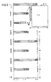
- FIG. 1 shows the French proposal for the formation of a synchronous transmission signal STM-1.
- Different plesiochronous signals H11 to H22 (M here means Mbit / s) indicated on the right-hand side can be combined via different multiplex paths to form the synchronous transmission signal STM-1.
- the arrow directions in FIG. 1 each indicate the direction to a more complex multiplex signal or to a multiplex signal of a higher level. The same multiplex path must be used on both sides of a digital connection.
- the top half shows the multiplex routes for signals of the 1.5 Mbit / s hierarchy (USA) and the bottom half shows the multiplex routes of the 2 Mbit / s hierarchy.
- the STM-1 frame has a period of 8 KHz and has 270 columns and 9 rows, corresponding to 270 x 9 bytes.
- the frame password determines the position of all required pointers of the data blocks to be transmitted directly or indirectly via further pointers.
- So-called cross-connectors are provided in the connection line network (FIG. 2), which make it possible to switch multiplex signals via different connection paths.
- the cross connectors can be switched through using a mechanical or electronic switching matrix. This can be a synchronous space switching matrix, but also a synchronous time slot switching matrix, a time slot coupled space switching matrix or a combination thereof.
- subscribers here are telephone subscribers with fixed or dial-up connections (F + W) who have access to the connecting line network directly or via a switching level.
- plesiochronous hierarchy allows for switching or reassignment in every hierarchy level (multiplex level)
- no interfaces are standardized in the synchronous hierarchy between the individual hierarchy levels below the STM-1 signal of 155.520 Mbit / s, which means switching through and switching is initially not possible.
- Desired switching levels in the 2 Mbit / s hierarchy would have to be provided for the data blocks TU-12, TU-22, TUG-22, TU-31, TUG-31, AU-31 and AU-4.
- the corresponding switching levels for data blocks TU-11, TU-21, TUG-21, TU-32, TUG-32, AU-32 and AU-4 would be desirable.
- the switching level AU-4 administers, which is not the subject of the invention
- the switching levels for the 2 Mbit / s hierarchy and for the 1.5 Mbit / s hierarchy require different devices.
- the object of the invention is therefore to provide a method that enables the switching of multiplex signals of the synchronous digital hierarchy. Suitable pulse frames must also be specified.
- the multiplex structure is shown both for the 2 Mbit / s hierarchy and for the 1.5 Mbit / s hierarchy.
- the specification 2M means a data rate of approx. 2 Mbit / s.
- the virtual containers C are transmitted periodically and combined to form larger data blocks.
- FIG. 3 shows a basic circuit diagram for converting the received signals into switchable signals DS 39 (DS 39 digital signal) of the switching level DE.
- DS 39 switchable signals
- 2 Mbit / s several signals (2 Mbit / s) are combined to form the DS 39 signal, which will be discussed in more detail later, while signals with a higher data rate are broken down into several DS 39 signals or converted into DS 39 signals.
- the diagram shown in FIG. 3 naturally also applies to the combination and division of switched through DS 39 signals.
- the STM-0 signal has not yet been set. It has a quarter of the data rate of the STM-0 signal.
- the received data blocks are arranged in an overframe under phase and frequency compensation (buffer memory, pointer action (i.e. change in the distance address specified by the pointer)) and by positive zero-negative stuffing.
- buffer memory pointer action (i.e. change in the distance address specified by the pointer)
- positive zero-negative stuffing When switching through, all data blocks such as TUs, TUGs or AUs newly combined in the superframe must be classified in the time slots assigned to them. For this purpose, all pointers must be arranged in the time slots provided for this, taking into account the superframe structure. An identifier must also be added to each signal to be switched through for coupling route monitoring.
- a suitable frame structure can be found for both the 2 Mbit / s hierarchy and the 1.5 Mbit / s hierarchy, which allows all TUs and TUGs to be switched through via a single time slot-controlled switching matrix.
- FIG. 4 shows the intermediate frame according to the invention for the 2 Mbit / s hierarchy.
- the superframe RM has - in two-dimensional representation - 152 rows with 16 columns each. It is divided into 4 frames RI to RIV, each containing 38 rows with 16 columns, i.e. 38 x 16 bytes.
- the transmission takes place line by line, starting with byte 1 in line Z1 and column S1. With a superframe period of 2 kHz, the transmission rate is 38 912 kbit / s (19 x 20 48 kbit / s). This transmission signal is the signal labeled DS 39.
- a frame identifier RRR ... is transmitted in the first line Z1 of the first frame RI.
- the first lines of the remaining frames RII to RIV and the first 7 bytes of an additional line - here the 20th line of each frame - are available for monitoring and management tasks (data A, B, C and x).
- the net transmission capacity of each frame is therefore 65 x 9 bytes. This corresponds exactly to the transmission rate of a TU-31 tributary unit.
- the frame identifier With the frame identifier in line 1 of the superframe or the frame RI, the frame structure with the additional lines and the lines for monitoring and management is defined. At the same time, the frame identifier determines the position of the pointers in the frame or superframe (arbitrarily).
- a TU-31 pointer consists of three bytes V1, V2 and V3, which occupy the same position in each of the frames RI-RIV. Which three time slots are used only has to be standardized if the signal packed in the frame is to be routed via an external interface.
- Bytes V1 and V2 indicate the location of the assigned data blocks.
- V3 is used as an "action byte" for tamping operations.
- the TU-31 pointers are arranged in time slots 8, 9 and 10 of the additional lines.
- the pointer In the TUG-22 tributary unit group, the pointer consists of 4 TU-12 pointers lined up; on the TU-31 the pointer consists of 16 TU-12 pointers lined up, each individual pointer in turn consists of four bytes V1-V4, which are distributed in this order to the frames RI-RIV.
- bytes V3 and V4 in frames RIII and RIV In principle, it does not matter which line number is used in the frame.
- the bytes are arranged on the 2nd line of each frame.
- the first lines of frames RII and RIII are preferably used for signal addresses for monitoring the coupling path, while the bytes of the 1st line of frame RIV can be used for quality monitoring of the coupling paths.
- FIG. 5 shows the insertion of a TU-31 in the overframe.
- the associated pointer H1, H2, H3 is arranged in three bytes (columns 8, 9 and 10) of the additional line.
- the pointer determines the position of the first byte (J1) of the virtual container VC-31.
- a total of four data blocks of a TU-31 signal can be inserted into the superframe RM.
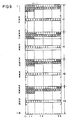
- FIG. 6 shows the division of the internal frame for signals TU-12, TU-22, TUG-22 and TUG-31.
- the bytes of the additional lines 20 of each frame remain unused for these signals.
- FIG. 7 shows the arrangement of 16 TU-12 (or a TUG-31). Each column is used to transmit a TU-12.
- the TU-12.1 is transmitted in the first column S1 and the TU-12.16 in the 16th column S16.
- the associated pointers V1-V4 are each arranged in the associated column in the second rows of the frames RI to RIV.
- FIG. 8 shows the arrangement of four TUG-22. 4 columns are required for each TUG-22, the first TUG-22 being assigned to columns S1, S5, S9 and S13, the second TUG-22 the columns S2, S6, S10 and S14, and the third TUG-22 the columns S3, S7, S11 and S15 and the fourth TUG-22 the remaining columns.
- the first TUG-22.1 is shown in FIG. 8 by puncturing the corresponding columns. The same column assignment applies to the transfer of tributary units TU-22.
- a TUG-22 can be formed from 5 x TU-11 instead of 4 x TU-12. In this case you need five instead of four pointers.
- the fifth pointers are each arranged in the first four bytes of the third line of each frame, into which the first, second, third and fourth bytes of the pointers are written. If the assignment is mixed, the corresponding pointers are omitted.
- five TU-11s are contained in all TUG-22s.
- FIG. 10 shows the insertion of five TUG-21 into the superframe RM for insertion into a TUG-31.
- the superframe - here RM - of the hierarchy into which the hierarchy is inserted is always used.
- the information bytes of the first column are set to a constant value (fixed stuff).
- the pointers are each divided into 2 lines of a frame.
- a similar RM 1.5 superframe according to FIG. 11 can be constructed for the 1.5 Mbit / s hierarchy; here each superframe consists of four frames R1-R4.
- the transmission rate is 51 968 kbit / s (29 x 1792 kbit / s). This signal is called DS 52.
- Line 15 is preferably used here as an additional line.
- the line Z1 from the frame R1 is given the frame identifier RR ...
- the first line of the frames R2 and R3 is used for the transmission of switching network addresses, and the first line of the frame R3 is used for the transmission of quality features.
- This superframe can be used to transmit a TU-32 or a TUG-32, seven TUG-21 or 28 TU-11.
- the additional lines for transmitting 28 TU-11 or seven TUG-21 or one TUG-32 are not used for information transmission.
- the pointer values V1, V2, V3 and V4 each occupy an entire line of the same position in the frames R1 to R4.
- 12 bytes of the additional line of each frame are required for the transmission of a TU-32.
- three TU-12 can also be transmitted.
- the two superframes for the 2 Mbit / s hierarchy and the 1.5 Mbit / s hierarchy it is possible to set up a cross connector for each of the two hierarchies, which with its switching matrix is capable of a TUG-31 or TUG-32 as a whole or divided into TUG-22 or TUG-21 or divided into TUG-22 and TU-12 or TUG-21 and TU-11.
- the cross-connector for the 2 Mbit / s is also able to connect 1 to 4 TUG-22s of a TUG-31, even if they are made up of 5 TU-11s each.
- switching from 1 to 7 TUG-21 or one TUG-32 applies accordingly, even if it contains three TU-12.
- TU-31 and AU-31 can also be switched through via the switching matrix.
- the AU-31 is referred to as the "Administrative Unit”.
- TU-32 or AU-32 can also be switched through via the switching matrix.
- the pointers can then be added to the 12 bytes of the additional line.
- the exact structure of the cross-connect data blocks to be switched can be found in the respective literature references.
Landscapes
- Engineering & Computer Science (AREA)
- Computer Networks & Wireless Communication (AREA)
- Signal Processing (AREA)
- Computer Hardware Design (AREA)
- Time-Division Multiplex Systems (AREA)
- Coupling Device And Connection With Printed Circuit (AREA)
- Use Of Switch Circuits For Exchanges And Methods Of Control Of Multiplex Exchanges (AREA)
- Emergency Protection Circuit Devices (AREA)
Applications Claiming Priority (2)
| Application Number | Priority Date | Filing Date | Title |
|---|---|---|---|
| DE3923172 | 1989-07-13 | ||
| DE3923172 | 1989-07-13 |
Publications (3)
| Publication Number | Publication Date |
|---|---|
| EP0407851A2 true EP0407851A2 (fr) | 1991-01-16 |
| EP0407851A3 EP0407851A3 (en) | 1992-06-17 |
| EP0407851B1 EP0407851B1 (fr) | 1996-02-07 |
Family
ID=6384954
Family Applications (1)
| Application Number | Title | Priority Date | Filing Date |
|---|---|---|---|
| EP90112593A Expired - Lifetime EP0407851B1 (fr) | 1989-07-13 | 1990-07-02 | Méthode pour l'interconnexion de signaux multiplexés par des connecteurs de répartitions |
Country Status (10)
| Country | Link |
|---|---|
| US (1) | US5123010A (fr) |
| EP (1) | EP0407851B1 (fr) |
| JP (1) | JPH0352428A (fr) |
| AT (1) | ATE134095T1 (fr) |
| AU (1) | AU627338B2 (fr) |
| CA (1) | CA2020937A1 (fr) |
| DE (1) | DE59010111D1 (fr) |
| DK (1) | DK0407851T3 (fr) |
| ES (1) | ES2082802T3 (fr) |
| GR (1) | GR3019081T3 (fr) |
Cited By (5)
| Publication number | Priority date | Publication date | Assignee | Title |
|---|---|---|---|---|
| WO1992014315A1 (fr) * | 1991-02-12 | 1992-08-20 | Siemens Aktiengesellschaft | Procede de reception et d'emission de binaires auxiliaires de signaux stm-1 dans des serveurs de binaires auxiliaires de n×uds de reseau |
| WO1993014582A1 (fr) * | 1992-01-15 | 1993-07-22 | Siemens Aktiengesellschaft | Procede de commutation de signaux numeriques |
| DE4309778C1 (de) * | 1993-03-25 | 1994-08-18 | Siemens Ag | Verfahren und Anordnung zum Einfügen eines 34 Mbit/s-Signals in D39-Pulsrahmen |
| US5555262A (en) * | 1992-11-19 | 1996-09-10 | Lucent Technologies Inc. | Transmission system of the synchronous digital hierarchy |
| DE19813936A1 (de) * | 1998-03-28 | 1999-09-30 | Cit Alcatel | Verfahren und Vorrichtung zur Mehrfachausnutzung eines Telekommunikationskanal |
Families Citing this family (9)
| Publication number | Priority date | Publication date | Assignee | Title |
|---|---|---|---|---|
| FR2659813B1 (fr) * | 1990-03-19 | 1994-06-03 | Cit Alcatel | Unite de commutation elementaire pour equipement de brassage de trains numeriques multiplexes par multiplexage temporel d'affluents numeriques a differents debits. |
| DE4108429A1 (de) * | 1991-03-15 | 1992-09-17 | Philips Patentverwaltung | Uebertragungssystem fuer die digitale synchrone hierarchie |
| DE4110933A1 (de) * | 1991-04-04 | 1992-10-08 | Philips Patentverwaltung | Uebertragungssystem fuer die synchrone digitale hierachie |
| JP2723699B2 (ja) * | 1991-07-31 | 1998-03-09 | 日本電気株式会社 | Tu−3ポインター付替処理方式 |
| FI93066C (fi) * | 1992-12-09 | 1995-02-10 | Nokia Telecommunications Oy | Multiplekseri ja demultiplekseri |
| US5436890A (en) * | 1993-12-30 | 1995-07-25 | Dsc Communications Corporation | Integrated multi-rate cross-connect system |
| DE19611236C1 (de) * | 1996-03-21 | 1996-11-21 | Siemens Ag | Verfahren zur Zuordnung von Zeitlagen zu einer Mehrkanal-Verbindung in einer Vermittlungseinrichtung |
| GB9718831D0 (en) * | 1997-09-05 | 1997-11-12 | Plessey Telecomm | Data transmission in an sdh network |
| EP1573945A2 (fr) * | 2000-06-15 | 2005-09-14 | Tyco Telecommunications (US) Inc. | Systeme et procede d'application de signaux a une structure de donnees a longueur de trame fixe |
Family Cites Families (6)
| Publication number | Priority date | Publication date | Assignee | Title |
|---|---|---|---|---|
| US3982077A (en) * | 1975-04-07 | 1976-09-21 | International Telephone And Telegraph Corporation | Asynchronous multiplexer and demultiplexer combination |
| EP0210611B1 (fr) * | 1985-07-31 | 1989-12-13 | Siemens Aktiengesellschaft | Méthode pour combiner un signal d'image numérique et trois signaux numériques à bande étroite dans un signal de 139 264-kbits/s |
| KR910001743B1 (ko) * | 1986-11-28 | 1991-03-22 | 미쓰비시덴기 가부시기가이샤 | 데이타 멀티 플렉스 전송 장치 |
| CA1264876A (fr) * | 1987-06-01 | 1990-01-23 | James Angus Mceachern | Synchronisation de signaux de donnees asynchrones |
| JPH01202946A (ja) * | 1988-02-08 | 1989-08-15 | Sumitomo Electric Ind Ltd | データ伝送方式 |
| US5214643A (en) * | 1988-05-11 | 1993-05-25 | Siemens Aktiengesellschaft | Method for inserting an asynchronous 139,264 kbit/s signal into a 155,520 kbit/s signal |
-
1990
- 1990-06-18 US US07/539,890 patent/US5123010A/en not_active Expired - Fee Related
- 1990-07-02 AT AT90112593T patent/ATE134095T1/de not_active IP Right Cessation
- 1990-07-02 EP EP90112593A patent/EP0407851B1/fr not_active Expired - Lifetime
- 1990-07-02 ES ES90112593T patent/ES2082802T3/es not_active Expired - Lifetime
- 1990-07-02 DE DE59010111T patent/DE59010111D1/de not_active Expired - Fee Related
- 1990-07-02 DK DK90112593.0T patent/DK0407851T3/da active
- 1990-07-10 JP JP2180721A patent/JPH0352428A/ja active Pending
- 1990-07-11 CA CA002020937A patent/CA2020937A1/fr not_active Abandoned
- 1990-07-12 AU AU58972/90A patent/AU627338B2/en not_active Ceased
-
1996
- 1996-02-22 GR GR960400491T patent/GR3019081T3/el unknown
Non-Patent Citations (6)
| Title |
|---|
| IEEE Global Telecommunications Conference & Exhibition 1987; Tokyo, JP ; 15.- 18. Nov. 1987; Band 1 Seiten 485 - 489 N.B. SANDESARA et al. : ' SYNCHRONOUS OPTICAL NETWORK FORMAT AND TERMINAL APPLICATIONS ' * |
| IEEE Global Telecommunications Conference & Exhibition 1989 ; Dallas, US 27 - 30. Nov. 1989 ; Band 3 Seiten 1506 - 1510 H. UEDA ET AL. : ' NEW SYNCHRONOUS DIGITAL TRANSMISSION SYSTEM WITH NETWORK NODE INTERFACE * |
| IEEE Global Telecommunications Conference & Exhibition; Hollywood, US 28. Nov. - 1. Dez. 1988; Band 2 Seiten 960 - 964 K. Maki et al. : ' IMPLEMENTATION AND APPLICATION OF EQUIPMENT WITH NETWORK NODE INTERFACE ' * |
| IEEE JOURNAL ON SELECTED AREAS IN COMMUNICATION. Bd. SAC-5, Nr. 1, Januar 1987, NEW YORK US Seiten 6 - 18; A. F. GRAVES ET AL.: 'An Experimental Cross-Connect System for Metropolitan Applications' * |
| NEC RESEARCH AND DEVELOPMENT. Bd. 92, Nr. 1, Januar 1989, TOKYO JP Seiten 81 - 88; Y. ROKUGO ET AL.: 'Digital Cross-Connect System NDC-A31' * |
| The International Symposium On Subscriber Loops And Services 1988 ; Boston, US 11-16 Sep. 1988 ; Seiten 174 - 178 ; G. Chopping et al. : ' TRANSMISSION PROTECTION AND INTERFACING IN THE SYNCHRONOUS LOCAL NETWORK' * |
Cited By (7)
| Publication number | Priority date | Publication date | Assignee | Title |
|---|---|---|---|---|
| WO1992014315A1 (fr) * | 1991-02-12 | 1992-08-20 | Siemens Aktiengesellschaft | Procede de reception et d'emission de binaires auxiliaires de signaux stm-1 dans des serveurs de binaires auxiliaires de n×uds de reseau |
| US5465252A (en) * | 1991-02-12 | 1995-11-07 | Siemens Aktiengesellschaft | Method for receiving and delivering section overheads of and for STM-1 signals in a section-overhead server of a network node |
| WO1993014582A1 (fr) * | 1992-01-15 | 1993-07-22 | Siemens Aktiengesellschaft | Procede de commutation de signaux numeriques |
| US5579310A (en) * | 1992-01-15 | 1996-11-26 | Siemens Aktiengesellschaft | Method for switching through digital signals |
| US5555262A (en) * | 1992-11-19 | 1996-09-10 | Lucent Technologies Inc. | Transmission system of the synchronous digital hierarchy |
| DE4309778C1 (de) * | 1993-03-25 | 1994-08-18 | Siemens Ag | Verfahren und Anordnung zum Einfügen eines 34 Mbit/s-Signals in D39-Pulsrahmen |
| DE19813936A1 (de) * | 1998-03-28 | 1999-09-30 | Cit Alcatel | Verfahren und Vorrichtung zur Mehrfachausnutzung eines Telekommunikationskanal |
Also Published As
| Publication number | Publication date |
|---|---|
| GR3019081T3 (en) | 1996-05-31 |
| DE59010111D1 (de) | 1996-03-21 |
| ATE134095T1 (de) | 1996-02-15 |
| AU5897290A (en) | 1991-01-17 |
| EP0407851B1 (fr) | 1996-02-07 |
| ES2082802T3 (es) | 1996-04-01 |
| DK0407851T3 (da) | 1996-04-15 |
| EP0407851A3 (en) | 1992-06-17 |
| CA2020937A1 (fr) | 1991-01-14 |
| US5123010A (en) | 1992-06-16 |
| AU627338B2 (en) | 1992-08-20 |
| JPH0352428A (ja) | 1991-03-06 |
Similar Documents
| Publication | Publication Date | Title |
|---|---|---|
| EP0429888B1 (fr) | Méthode de transmission par un réseau multiplex hierarchisé synchrone et numérique d'un signal à large bande distribué entre des unités de transmission subordonnées | |
| DE69327479T2 (de) | Verfahren zum zerlegen und zusammensetzen von rahmenstrukturen mit zeigern | |
| EP0422443B1 (fr) | Multiplexeur et démultiplexeur, notamment pour réseaux de transmission d'informations sur une hiérarchie synchrone de signaux numériques | |
| EP0407851B1 (fr) | Méthode pour l'interconnexion de signaux multiplexés par des connecteurs de répartitions | |
| DE69227736T2 (de) | Einfügen des "virtueller untergeordneter Pfad ist leer" Signals unter Verwendung des Zeitschlitzvermittlungsverfahrens | |
| DE69132247T2 (de) | Phasenverriegelte Schleifenanordnung | |
| DE2825954C2 (de) | Digitale Zeitmultiplexanlage | |
| DE69327412T2 (de) | Verfahren und einrichtung zur elastischen pufferung in einem synchronen digitalen fernmeldesystem | |
| DE69322784T2 (de) | Verfahren zur durchführung einer vermittlung im zeit- oder raumbereich | |
| DE4326664C2 (de) | V.110-Kommunikationsprotokoll-Teildatenratenadapter für ein ISDN-Netz | |
| EP0598455B1 (fr) | Système de transmission pour la hiérarchie numérique synchrone | |
| EP0777351A2 (fr) | Système de transmission numérique synchrone | |
| DE69320478T2 (de) | Verfahren und einrichtung zur überwachung der füllrate eines elastischen pufferspeichers in einem synchronen digitalen fernmeldesystem | |
| DE60320266T2 (de) | Synchroner übertragungsnetzknoten | |
| LU87713A1 (de) | Kreuzschaltungsverfahren(cross-connect)fuer stm-1-signale der synchron-digital-multiplexhierarchie | |
| DE68921917T2 (de) | Zeitmultiplex-Datenübertragungssystem. | |
| DE19943625A1 (de) | Verfahren und Vorrichtung zum Umwandeln eines SONET-Signals in ein SDH-Signal | |
| DE19627728A1 (de) | Netzelement und Ein-/Ausgabeeinheit für ein synchrones Übertragungssystem | |
| DE69028436T2 (de) | Sonet-Sendesignalierungsumsetzer | |
| EP0647379B1 (fr) | Procede de commutation de signaux numeriques | |
| DE69420719T2 (de) | Verfahren und vorrichtung zum bestimmen einer stopfentscheidung in einem knoten eines synchronen digitalen nachrichtenübertragungssystems (sdh) | |
| EP0565890A2 (fr) | Méthode et dispositif de transmission d'un signal numérique par un support VC-12 sur des canaux de données | |
| DE69326468T2 (de) | Verfahren zur durchführung einer zeitvermittlung und zeitvermittlungsanlage | |
| EP0143268A2 (fr) | Procédé et dispositif pour intercaler un signal numérique binaire à bande étroite dans, ou pour extraire ce signal à bande étroite d'un signal à multiplexage dans le temps | |
| DE69703718T2 (de) | Hybrider Multiplexer |
Legal Events
| Date | Code | Title | Description |
|---|---|---|---|
| PUAI | Public reference made under article 153(3) epc to a published international application that has entered the european phase |
Free format text: ORIGINAL CODE: 0009012 |
|
| AK | Designated contracting states |
Kind code of ref document: A2 Designated state(s): AT BE CH DE DK ES FR GB GR IT LI NL SE |
|
| 17P | Request for examination filed |
Effective date: 19901205 |
|
| PUAL | Search report despatched |
Free format text: ORIGINAL CODE: 0009013 |
|
| AK | Designated contracting states |
Kind code of ref document: A3 Designated state(s): AT BE CH DE DK ES FR GB GR IT LI NL SE |
|
| 17Q | First examination report despatched |
Effective date: 19940816 |
|
| GRAA | (expected) grant |
Free format text: ORIGINAL CODE: 0009210 |
|
| AK | Designated contracting states |
Kind code of ref document: B1 Designated state(s): AT BE CH DE DK ES FR GB GR IT LI NL SE |
|
| PG25 | Lapsed in a contracting state [announced via postgrant information from national office to epo] |
Ref country code: GR Free format text: LAPSE BECAUSE OF FAILURE TO SUBMIT A TRANSLATION OF THE DESCRIPTION OR TO PAY THE FEE WITHIN THE PRESCRIBED TIME-LIMIT Effective date: 19960207 |
|
| REF | Corresponds to: |
Ref document number: 134095 Country of ref document: AT Date of ref document: 19960215 Kind code of ref document: T |
|
| REF | Corresponds to: |
Ref document number: 59010111 Country of ref document: DE Date of ref document: 19960321 |
|
| REG | Reference to a national code |
Ref country code: CH Ref legal event code: NV Representative=s name: SIEMENS SCHWEIZ AG |
|
| REG | Reference to a national code |
Ref country code: ES Ref legal event code: FG2A Ref document number: 2082802 Country of ref document: ES Kind code of ref document: T3 |
|
| REG | Reference to a national code |
Ref country code: DK Ref legal event code: T3 |
|
| ITF | It: translation for a ep patent filed | ||
| REG | Reference to a national code |
Ref country code: GR Ref legal event code: FG4A Free format text: 3019081 |
|
| ET | Fr: translation filed | ||
| GBT | Gb: translation of ep patent filed (gb section 77(6)(a)/1977) |
Effective date: 19960515 |
|
| PG25 | Lapsed in a contracting state [announced via postgrant information from national office to epo] |
Ref country code: DK Effective date: 19960702 Ref country code: AT Effective date: 19960702 |
|
| REG | Reference to a national code |
Ref country code: DK Ref legal event code: EBP |
|
| PG25 | Lapsed in a contracting state [announced via postgrant information from national office to epo] |
Ref country code: SE Effective date: 19960703 |
|
| PG25 | Lapsed in a contracting state [announced via postgrant information from national office to epo] |
Ref country code: LI Effective date: 19960731 Ref country code: CH Effective date: 19960731 Ref country code: BE Effective date: 19960731 |
|
| PLBE | No opposition filed within time limit |
Free format text: ORIGINAL CODE: 0009261 |
|
| STAA | Information on the status of an ep patent application or granted ep patent |
Free format text: STATUS: NO OPPOSITION FILED WITHIN TIME LIMIT |
|
| BERE | Be: lapsed |
Owner name: SIEMENS A.G. Effective date: 19960731 |
|
| PG25 | Lapsed in a contracting state [announced via postgrant information from national office to epo] |
Ref country code: NL Effective date: 19970201 |
|
| 26N | No opposition filed | ||
| REG | Reference to a national code |
Ref country code: GR Ref legal event code: MM2A Free format text: 3019081 |
|
| REG | Reference to a national code |
Ref country code: CH Ref legal event code: PL |
|
| NLV4 | Nl: lapsed or anulled due to non-payment of the annual fee |
Effective date: 19970201 |
|
| EUG | Se: european patent has lapsed |
Ref document number: 90112593.0 |
|
| PGFP | Annual fee paid to national office [announced via postgrant information from national office to epo] |
Ref country code: GB Payment date: 19980623 Year of fee payment: 9 |
|
| PGFP | Annual fee paid to national office [announced via postgrant information from national office to epo] |
Ref country code: ES Payment date: 19980707 Year of fee payment: 9 |
|
| PGFP | Annual fee paid to national office [announced via postgrant information from national office to epo] |
Ref country code: FR Payment date: 19980729 Year of fee payment: 9 |
|
| PGFP | Annual fee paid to national office [announced via postgrant information from national office to epo] |
Ref country code: DE Payment date: 19980917 Year of fee payment: 9 |
|
| PG25 | Lapsed in a contracting state [announced via postgrant information from national office to epo] |
Ref country code: GB Free format text: LAPSE BECAUSE OF NON-PAYMENT OF DUE FEES Effective date: 19990702 |
|
| PG25 | Lapsed in a contracting state [announced via postgrant information from national office to epo] |
Ref country code: ES Free format text: LAPSE BECAUSE OF NON-PAYMENT OF DUE FEES Effective date: 19990703 |
|
| PG25 | Lapsed in a contracting state [announced via postgrant information from national office to epo] |
Ref country code: FR Free format text: THE PATENT HAS BEEN ANNULLED BY A DECISION OF A NATIONAL AUTHORITY Effective date: 19990731 |
|
| GBPC | Gb: european patent ceased through non-payment of renewal fee |
Effective date: 19990702 |
|
| PG25 | Lapsed in a contracting state [announced via postgrant information from national office to epo] |
Ref country code: DE Free format text: LAPSE BECAUSE OF NON-PAYMENT OF DUE FEES Effective date: 20000503 |
|
| REG | Reference to a national code |
Ref country code: FR Ref legal event code: ST |
|
| REG | Reference to a national code |
Ref country code: ES Ref legal event code: FD2A Effective date: 20020603 |
|
| PG25 | Lapsed in a contracting state [announced via postgrant information from national office to epo] |
Ref country code: IT Free format text: LAPSE BECAUSE OF NON-PAYMENT OF DUE FEES;WARNING: LAPSES OF ITALIAN PATENTS WITH EFFECTIVE DATE BEFORE 2007 MAY HAVE OCCURRED AT ANY TIME BEFORE 2007. THE CORRECT EFFECTIVE DATE MAY BE DIFFERENT FROM THE ONE RECORDED. Effective date: 20050702 |