EP0407915A2 - Catalyseur pour la purification de gaz d'échappement - Google Patents
Catalyseur pour la purification de gaz d'échappement Download PDFInfo
- Publication number
- EP0407915A2 EP0407915A2 EP90112951A EP90112951A EP0407915A2 EP 0407915 A2 EP0407915 A2 EP 0407915A2 EP 90112951 A EP90112951 A EP 90112951A EP 90112951 A EP90112951 A EP 90112951A EP 0407915 A2 EP0407915 A2 EP 0407915A2
- Authority
- EP
- European Patent Office
- Prior art keywords
- catalyst
- weight
- coat layer
- cerium oxide
- oxide
- Prior art date
- Legal status (The legal status is an assumption and is not a legal conclusion. Google has not performed a legal analysis and makes no representation as to the accuracy of the status listed.)
- Granted
Links
- 239000003054 catalyst Substances 0.000 title claims abstract description 192
- 239000007789 gas Substances 0.000 title claims description 47
- 238000000746 purification Methods 0.000 title description 22
- QVQLCTNNEUAWMS-UHFFFAOYSA-N barium oxide Chemical compound [Ba]=O QVQLCTNNEUAWMS-UHFFFAOYSA-N 0.000 claims abstract description 145
- 229910000420 cerium oxide Inorganic materials 0.000 claims abstract description 98
- BMMGVYCKOGBVEV-UHFFFAOYSA-N oxo(oxoceriooxy)cerium Chemical compound [Ce]=O.O=[Ce]=O BMMGVYCKOGBVEV-UHFFFAOYSA-N 0.000 claims abstract description 98
- PNEYBMLMFCGWSK-UHFFFAOYSA-N aluminium oxide Inorganic materials [O-2].[O-2].[O-2].[Al+3].[Al+3] PNEYBMLMFCGWSK-UHFFFAOYSA-N 0.000 claims abstract description 34
- 239000002245 particle Substances 0.000 claims abstract description 31
- 229910000510 noble metal Inorganic materials 0.000 claims abstract description 17
- MRELNEQAGSRDBK-UHFFFAOYSA-N lanthanum(3+);oxygen(2-) Chemical compound [O-2].[O-2].[O-2].[La+3].[La+3] MRELNEQAGSRDBK-UHFFFAOYSA-N 0.000 claims description 50
- BASFCYQUMIYNBI-UHFFFAOYSA-N platinum Chemical compound [Pt] BASFCYQUMIYNBI-UHFFFAOYSA-N 0.000 claims description 35
- KDLHZDBZIXYQEI-UHFFFAOYSA-N Palladium Chemical compound [Pd] KDLHZDBZIXYQEI-UHFFFAOYSA-N 0.000 claims description 16
- 239000010948 rhodium Substances 0.000 claims description 16
- 229910052697 platinum Inorganic materials 0.000 claims description 15
- 229910052703 rhodium Inorganic materials 0.000 claims description 14
- MHOVAHRLVXNVSD-UHFFFAOYSA-N rhodium atom Chemical compound [Rh] MHOVAHRLVXNVSD-UHFFFAOYSA-N 0.000 claims description 14
- 229910052763 palladium Inorganic materials 0.000 claims description 8
- 239000013078 crystal Substances 0.000 abstract description 7
- 229910052684 Cerium Inorganic materials 0.000 abstract description 3
- GWXLDORMOJMVQZ-UHFFFAOYSA-N cerium Chemical compound [Ce] GWXLDORMOJMVQZ-UHFFFAOYSA-N 0.000 abstract 1
- RWSOTUBLDIXVET-UHFFFAOYSA-N Dihydrogen sulfide Chemical compound S RWSOTUBLDIXVET-UHFFFAOYSA-N 0.000 description 40
- 229910000037 hydrogen sulfide Inorganic materials 0.000 description 39
- 239000002002 slurry Substances 0.000 description 36
- RAHZWNYVWXNFOC-UHFFFAOYSA-N Sulphur dioxide Chemical compound O=S=O RAHZWNYVWXNFOC-UHFFFAOYSA-N 0.000 description 30
- 238000000034 method Methods 0.000 description 24
- IWOUKMZUPDVPGQ-UHFFFAOYSA-N barium nitrate Chemical compound [Ba+2].[O-][N+]([O-])=O.[O-][N+]([O-])=O IWOUKMZUPDVPGQ-UHFFFAOYSA-N 0.000 description 21
- 239000000446 fuel Substances 0.000 description 21
- 229930195733 hydrocarbon Natural products 0.000 description 20
- 150000002430 hydrocarbons Chemical class 0.000 description 20
- 230000000052 comparative effect Effects 0.000 description 17
- PXHVJJICTQNCMI-UHFFFAOYSA-N Nickel Chemical compound [Ni] PXHVJJICTQNCMI-UHFFFAOYSA-N 0.000 description 15
- 238000012360 testing method Methods 0.000 description 15
- 230000000694 effects Effects 0.000 description 13
- 229910052751 metal Inorganic materials 0.000 description 12
- 239000002184 metal Substances 0.000 description 12
- QVGXLLKOCUKJST-UHFFFAOYSA-N atomic oxygen Chemical compound [O] QVGXLLKOCUKJST-UHFFFAOYSA-N 0.000 description 10
- 239000001301 oxygen Substances 0.000 description 10
- 229910052760 oxygen Inorganic materials 0.000 description 10
- 238000006722 reduction reaction Methods 0.000 description 10
- 238000007664 blowing Methods 0.000 description 9
- 230000003197 catalytic effect Effects 0.000 description 9
- 230000009467 reduction Effects 0.000 description 9
- XLYOFNOQVPJJNP-UHFFFAOYSA-N water Substances O XLYOFNOQVPJJNP-UHFFFAOYSA-N 0.000 description 9
- 229910015853 MSO4 Inorganic materials 0.000 description 8
- 229910052788 barium Inorganic materials 0.000 description 8
- DSAJWYNOEDNPEQ-UHFFFAOYSA-N barium atom Chemical compound [Ba] DSAJWYNOEDNPEQ-UHFFFAOYSA-N 0.000 description 8
- 229910001593 boehmite Inorganic materials 0.000 description 8
- 230000006866 deterioration Effects 0.000 description 8
- FAHBNUUHRFUEAI-UHFFFAOYSA-M hydroxidooxidoaluminium Chemical compound O[Al]=O FAHBNUUHRFUEAI-UHFFFAOYSA-M 0.000 description 8
- FYDKNKUEBJQCCN-UHFFFAOYSA-N lanthanum(3+);trinitrate Chemical compound [La+3].[O-][N+]([O-])=O.[O-][N+]([O-])=O.[O-][N+]([O-])=O FYDKNKUEBJQCCN-UHFFFAOYSA-N 0.000 description 8
- 239000000203 mixture Substances 0.000 description 8
- 229910052759 nickel Inorganic materials 0.000 description 8
- TZCXTZWJZNENPQ-UHFFFAOYSA-L barium sulfate Chemical compound [Ba+2].[O-]S([O-])(=O)=O TZCXTZWJZNENPQ-UHFFFAOYSA-L 0.000 description 7
- 230000015572 biosynthetic process Effects 0.000 description 7
- MWUXSHHQAYIFBG-UHFFFAOYSA-N nitrogen oxide Inorganic materials O=[N] MWUXSHHQAYIFBG-UHFFFAOYSA-N 0.000 description 7
- 150000003839 salts Chemical class 0.000 description 7
- UFHFLCQGNIYNRP-UHFFFAOYSA-N Hydrogen Chemical compound [H][H] UFHFLCQGNIYNRP-UHFFFAOYSA-N 0.000 description 6
- GRYLNZFGIOXLOG-UHFFFAOYSA-N Nitric acid Chemical class O[N+]([O-])=O GRYLNZFGIOXLOG-UHFFFAOYSA-N 0.000 description 5
- NINIDFKCEFEMDL-UHFFFAOYSA-N Sulfur Chemical compound [S] NINIDFKCEFEMDL-UHFFFAOYSA-N 0.000 description 5
- 238000006243 chemical reaction Methods 0.000 description 5
- 239000001257 hydrogen Substances 0.000 description 5
- 229910052739 hydrogen Inorganic materials 0.000 description 5
- 230000003647 oxidation Effects 0.000 description 5
- 238000007254 oxidation reaction Methods 0.000 description 5
- 229910052717 sulfur Inorganic materials 0.000 description 5
- 239000011593 sulfur Substances 0.000 description 5
- AZRCLCUGADNYQP-UHFFFAOYSA-H cerium(3+) trisulfite Chemical compound [Ce+3].[Ce+3].[O-]S([O-])=O.[O-]S([O-])=O.[O-]S([O-])=O AZRCLCUGADNYQP-UHFFFAOYSA-H 0.000 description 4
- 231100001261 hazardous Toxicity 0.000 description 4
- 229910017604 nitric acid Inorganic materials 0.000 description 4
- 239000011148 porous material Substances 0.000 description 4
- 239000000843 powder Substances 0.000 description 4
- 239000004215 Carbon black (E152) Substances 0.000 description 3
- 229910052593 corundum Inorganic materials 0.000 description 3
- 238000000151 deposition Methods 0.000 description 3
- 238000005516 engineering process Methods 0.000 description 3
- 230000007246 mechanism Effects 0.000 description 3
- 150000002736 metal compounds Chemical class 0.000 description 3
- PIBWKRNGBLPSSY-UHFFFAOYSA-L palladium(II) chloride Chemical compound Cl[Pd]Cl PIBWKRNGBLPSSY-UHFFFAOYSA-L 0.000 description 3
- 150000003058 platinum compounds Chemical class 0.000 description 3
- CLSUSRZJUQMOHH-UHFFFAOYSA-L platinum dichloride Chemical compound Cl[Pt]Cl CLSUSRZJUQMOHH-UHFFFAOYSA-L 0.000 description 3
- 150000003284 rhodium compounds Chemical class 0.000 description 3
- 239000007787 solid Substances 0.000 description 3
- 229910001845 yogo sapphire Inorganic materials 0.000 description 3
- XEEYBQQBJWHFJM-UHFFFAOYSA-N Iron Chemical compound [Fe] XEEYBQQBJWHFJM-UHFFFAOYSA-N 0.000 description 2
- QCWXUUIWCKQGHC-UHFFFAOYSA-N Zirconium Chemical compound [Zr] QCWXUUIWCKQGHC-UHFFFAOYSA-N 0.000 description 2
- 230000004931 aggregating effect Effects 0.000 description 2
- CJDPJFRMHVXWPT-UHFFFAOYSA-N barium sulfide Chemical compound [S-2].[Ba+2] CJDPJFRMHVXWPT-UHFFFAOYSA-N 0.000 description 2
- 238000001354 calcination Methods 0.000 description 2
- ZMIGMASIKSOYAM-UHFFFAOYSA-N cerium Chemical compound [Ce][Ce][Ce][Ce][Ce][Ce][Ce][Ce][Ce][Ce][Ce][Ce][Ce][Ce][Ce][Ce][Ce][Ce][Ce][Ce][Ce][Ce][Ce][Ce][Ce][Ce][Ce][Ce][Ce][Ce][Ce][Ce][Ce][Ce][Ce][Ce][Ce][Ce] ZMIGMASIKSOYAM-UHFFFAOYSA-N 0.000 description 2
- 239000011248 coating agent Substances 0.000 description 2
- 238000000576 coating method Methods 0.000 description 2
- 238000002485 combustion reaction Methods 0.000 description 2
- 238000007599 discharging Methods 0.000 description 2
- 238000001035 drying Methods 0.000 description 2
- 230000001473 noxious effect Effects 0.000 description 2
- VXNYVYJABGOSBX-UHFFFAOYSA-N rhodium(3+);trinitrate Chemical compound [Rh+3].[O-][N+]([O-])=O.[O-][N+]([O-])=O.[O-][N+]([O-])=O VXNYVYJABGOSBX-UHFFFAOYSA-N 0.000 description 2
- SONJTKJMTWTJCT-UHFFFAOYSA-K rhodium(iii) chloride Chemical compound [Cl-].[Cl-].[Cl-].[Rh+3] SONJTKJMTWTJCT-UHFFFAOYSA-K 0.000 description 2
- 238000005245 sintering Methods 0.000 description 2
- 229910052726 zirconium Inorganic materials 0.000 description 2
- OYPRJOBELJOOCE-UHFFFAOYSA-N Calcium Chemical compound [Ca] OYPRJOBELJOOCE-UHFFFAOYSA-N 0.000 description 1
- 208000005623 Carcinogenesis Diseases 0.000 description 1
- VYZAMTAEIAYCRO-UHFFFAOYSA-N Chromium Chemical compound [Cr] VYZAMTAEIAYCRO-UHFFFAOYSA-N 0.000 description 1
- XUIMIQQOPSSXEZ-UHFFFAOYSA-N Silicon Chemical compound [Si] XUIMIQQOPSSXEZ-UHFFFAOYSA-N 0.000 description 1
- ATJFFYVFTNAWJD-UHFFFAOYSA-N Tin Chemical compound [Sn] ATJFFYVFTNAWJD-UHFFFAOYSA-N 0.000 description 1
- 230000002411 adverse Effects 0.000 description 1
- 239000004411 aluminium Substances 0.000 description 1
- 229910052782 aluminium Inorganic materials 0.000 description 1
- XAGFODPZIPBFFR-UHFFFAOYSA-N aluminium Chemical compound [Al] XAGFODPZIPBFFR-UHFFFAOYSA-N 0.000 description 1
- 229910000329 aluminium sulfate Inorganic materials 0.000 description 1
- DIZPMCHEQGEION-UHFFFAOYSA-H aluminium sulfate (anhydrous) Chemical compound [Al+3].[Al+3].[O-]S([O-])(=O)=O.[O-]S([O-])(=O)=O.[O-]S([O-])(=O)=O DIZPMCHEQGEION-UHFFFAOYSA-H 0.000 description 1
- 235000011128 aluminium sulphate Nutrition 0.000 description 1
- 229910001422 barium ion Inorganic materials 0.000 description 1
- 229910052791 calcium Inorganic materials 0.000 description 1
- 239000011575 calcium Substances 0.000 description 1
- 230000036952 cancer formation Effects 0.000 description 1
- 229910052799 carbon Inorganic materials 0.000 description 1
- 231100000504 carcinogenesis Toxicity 0.000 description 1
- 238000006555 catalytic reaction Methods 0.000 description 1
- 239000000919 ceramic Substances 0.000 description 1
- 229910000421 cerium(III) oxide Inorganic materials 0.000 description 1
- 229910000355 cerium(IV) sulfate Inorganic materials 0.000 description 1
- 229910052804 chromium Inorganic materials 0.000 description 1
- 239000011651 chromium Substances 0.000 description 1
- 239000000470 constituent Substances 0.000 description 1
- 238000010276 construction Methods 0.000 description 1
- 229910052878 cordierite Inorganic materials 0.000 description 1
- 230000008021 deposition Effects 0.000 description 1
- YDIQKOIXOOOXQQ-UHFFFAOYSA-H dialuminum;trisulfite Chemical compound [Al+3].[Al+3].[O-]S([O-])=O.[O-]S([O-])=O.[O-]S([O-])=O YDIQKOIXOOOXQQ-UHFFFAOYSA-H 0.000 description 1
- JSKIRARMQDRGJZ-UHFFFAOYSA-N dimagnesium dioxido-bis[(1-oxido-3-oxo-2,4,6,8,9-pentaoxa-1,3-disila-5,7-dialuminabicyclo[3.3.1]nonan-7-yl)oxy]silane Chemical compound [Mg++].[Mg++].[O-][Si]([O-])(O[Al]1O[Al]2O[Si](=O)O[Si]([O-])(O1)O2)O[Al]1O[Al]2O[Si](=O)O[Si]([O-])(O1)O2 JSKIRARMQDRGJZ-UHFFFAOYSA-N 0.000 description 1
- 239000006185 dispersion Substances 0.000 description 1
- 238000002474 experimental method Methods 0.000 description 1
- 150000002431 hydrogen Chemical class 0.000 description 1
- -1 i.e. Chemical compound 0.000 description 1
- 239000012784 inorganic fiber Substances 0.000 description 1
- 229910052742 iron Inorganic materials 0.000 description 1
- 229910044991 metal oxide Inorganic materials 0.000 description 1
- 150000004706 metal oxides Chemical class 0.000 description 1
- 229910052976 metal sulfide Inorganic materials 0.000 description 1
- 230000005012 migration Effects 0.000 description 1
- 238000013508 migration Methods 0.000 description 1
- 238000012986 modification Methods 0.000 description 1
- 230000004048 modification Effects 0.000 description 1
- 230000001590 oxidative effect Effects 0.000 description 1
- 230000002265 prevention Effects 0.000 description 1
- 238000009877 rendering Methods 0.000 description 1
- 229910052710 silicon Inorganic materials 0.000 description 1
- 239000010703 silicon Substances 0.000 description 1
- 230000000087 stabilizing effect Effects 0.000 description 1
- 229910052712 strontium Inorganic materials 0.000 description 1
- CIOAGBVUUVVLOB-UHFFFAOYSA-N strontium atom Chemical compound [Sr] CIOAGBVUUVVLOB-UHFFFAOYSA-N 0.000 description 1
- 125000001424 substituent group Chemical group 0.000 description 1
- WWNBZGLDODTKEM-UHFFFAOYSA-N sulfanylidenenickel Chemical compound [Ni]=S WWNBZGLDODTKEM-UHFFFAOYSA-N 0.000 description 1
- 150000003467 sulfuric acid derivatives Chemical class 0.000 description 1
- 230000001629 suppression Effects 0.000 description 1
- 229910052718 tin Inorganic materials 0.000 description 1
- WFKWXMTUELFFGS-UHFFFAOYSA-N tungsten Chemical compound [W] WFKWXMTUELFFGS-UHFFFAOYSA-N 0.000 description 1
- 229910052721 tungsten Inorganic materials 0.000 description 1
- 239000010937 tungsten Substances 0.000 description 1
Images





Classifications
-
- B—PERFORMING OPERATIONS; TRANSPORTING
- B01—PHYSICAL OR CHEMICAL PROCESSES OR APPARATUS IN GENERAL
- B01J—CHEMICAL OR PHYSICAL PROCESSES, e.g. CATALYSIS OR COLLOID CHEMISTRY; THEIR RELEVANT APPARATUS
- B01J23/00—Catalysts comprising metals or metal oxides or hydroxides, not provided for in group B01J21/00
- B01J23/38—Catalysts comprising metals or metal oxides or hydroxides, not provided for in group B01J21/00 of noble metals
- B01J23/54—Catalysts comprising metals or metal oxides or hydroxides, not provided for in group B01J21/00 of noble metals combined with metals, oxides or hydroxides provided for in groups B01J23/02 - B01J23/36
- B01J23/56—Platinum group metals
- B01J23/63—Platinum group metals with rare earths or actinides
-
- B—PERFORMING OPERATIONS; TRANSPORTING
- B01—PHYSICAL OR CHEMICAL PROCESSES OR APPARATUS IN GENERAL
- B01D—SEPARATION
- B01D53/00—Separation of gases or vapours; Recovering vapours of volatile solvents from gases; Chemical or biological purification of waste gases, e.g. engine exhaust gases, smoke, fumes, flue gases, aerosols
- B01D53/34—Chemical or biological purification of waste gases
- B01D53/92—Chemical or biological purification of waste gases of engine exhaust gases
- B01D53/94—Chemical or biological purification of waste gases of engine exhaust gases by catalytic processes
- B01D53/9445—Simultaneously removing carbon monoxide, hydrocarbons or nitrogen oxides making use of three-way catalysts [TWC] or four-way-catalysts [FWC]
- B01D53/945—Simultaneously removing carbon monoxide, hydrocarbons or nitrogen oxides making use of three-way catalysts [TWC] or four-way-catalysts [FWC] characterised by a specific catalyst
-
- B—PERFORMING OPERATIONS; TRANSPORTING
- B01—PHYSICAL OR CHEMICAL PROCESSES OR APPARATUS IN GENERAL
- B01J—CHEMICAL OR PHYSICAL PROCESSES, e.g. CATALYSIS OR COLLOID CHEMISTRY; THEIR RELEVANT APPARATUS
- B01J23/00—Catalysts comprising metals or metal oxides or hydroxides, not provided for in group B01J21/00
- B01J23/38—Catalysts comprising metals or metal oxides or hydroxides, not provided for in group B01J21/00 of noble metals
- B01J23/54—Catalysts comprising metals or metal oxides or hydroxides, not provided for in group B01J21/00 of noble metals combined with metals, oxides or hydroxides provided for in groups B01J23/02 - B01J23/36
- B01J23/56—Platinum group metals
- B01J23/58—Platinum group metals with alkali- or alkaline earth metals
-
- Y—GENERAL TAGGING OF NEW TECHNOLOGICAL DEVELOPMENTS; GENERAL TAGGING OF CROSS-SECTIONAL TECHNOLOGIES SPANNING OVER SEVERAL SECTIONS OF THE IPC; TECHNICAL SUBJECTS COVERED BY FORMER USPC CROSS-REFERENCE ART COLLECTIONS [XRACs] AND DIGESTS
- Y02—TECHNOLOGIES OR APPLICATIONS FOR MITIGATION OR ADAPTATION AGAINST CLIMATE CHANGE
- Y02T—CLIMATE CHANGE MITIGATION TECHNOLOGIES RELATED TO TRANSPORTATION
- Y02T10/00—Road transport of goods or passengers
- Y02T10/10—Internal combustion engine [ICE] based vehicles
- Y02T10/12—Improving ICE efficiencies
Definitions
- the present invention relates to a catalyst for the purification of exhaust gases and, more particularly, to a catalyst mounted to an exhaust system for purifying exhaust gases by adsorbing hazardous components thereof.
- Exhaust gases from vehicles are purified by removing their hazardous and noxious components such as NOx, CO and so on by, for example, ternary catalysts which may be disposed in the exhaust system.
- U. S. Patent No. 4,888,320 discloses a catalyst composed of a catalyst carrier with two coats deposited thereon. Specifically, a first coat is deposited on a surface of the catalyst carrier and a second coat is further deposited on a surface of the first coat and, more specifically, the first coat is comprised of alumina and the second coat is comprised of alumina containing cerium oxide CeO2, platinum Pt and rhodium Rh. As the second coat is formed on the alumina layer as the first coat, the second coat containing a catalyst constituent such as platinum can be made uniform in coat thickness, preventing the catalyst component from sintering.
- Japanese Patent Unexamined Publication (kokai) No. 113,487/1975 discloses a catalyst for the purification of exhaust gases in which a platinum group metal is deposited on the coat layer formed on the catalyst carrier comprised of active alumina by preparing a slurry solution containing at least one of chromium and tungsten and at least one of calcium, strontium, barium, silicon, tin and zirconium and coating the slurry solution on the surface of the carrier.
- Japanese Patent Unexamined Publication (kokai) No. 71,536/1987 discloses a catalyst consisting of a first coat layer comprised of alumina containing platinum and rhodium and a second coat layer, which is formed on the first coat layer, containing cerium oxide and palladium.
- Japanese Patent Examined Publication (kokoku) No. 14,338/1987 discloses technology of forming a coat on the surface of a catalyst carrier by preparing a slurry from a mixture of an active alumina with at least one of cerium, zirconium, iron and nickel and at least one ofplatinum, palladium and rhodium, coating the slurry on thesurface of the carrier to form a wash coat as well as drying and calcining the wash coat.
- the coat with cerium oxide contained therein can exhibit the effect of storing oxygen due to the cerium oxide.
- This effect of storing oxygen is such that, when the concentration of oxygen is high, namely, when the air/fuel ratio is on the lean side, the oxygen is adsorbed while, when the concentration of oxygen is low, namely, when the air/fuel ratio is on the rich side, the oxygen is discharged, thereby contributing to the catalytic reaction of the catalyst. Therefore, due to the catalytic effect of storing oxygen to be achieved by the cerium oxide contained in the catalyst, the catalyst has an extended region of the air/fuel ratio in which the catalyst can react with nitrogen oxides (NOx), hydrocarbons (HC) and so on. Hence, cerium oxide contributes to improvements in catalytic performance.
- NOx nitrogen oxides
- HC hydrocarbons
- cerium oxide itself can react with water to cause a reaction with hydrogen gas, thereby serving as improvements in catalytic performance.
- Cerium oxide may have the tendency that its crystal grows and its crystalline structure is rendered so large that a specific surface area of the cerium oxide becomes small. A smaller specific surface area of the cerium oxide results in a reduction in the catalytic effect of storing oxygen and in the reaction with hydrogen gas.
- cerium oxide contained in the catalyst causes heat deterioration on account of the crystal growth due to a high-temperature heat applied to the catalyst from exhuast gases suffers from the difficulty to stabilize the catalytic activity of the catalyst with the cerium oxide contained therein at low temperatures.
- the present invention has been performed in the situation as described hereinabove and under such conditions where the engine output power becomes high and great improvements have been achieved in fuel and emission performance, thereby causing exhaust gases to become higher in temperature.
- the present invention has the object to provide a catalyst for the purification of exhaust gases with improved heat resistance, adaptable to withstand heat deterioration of cerium oxide contained in the catalyst and, as a result, to improve heat resistance of the catalyst resulting in improvements in the overall catalytic performance of the catalyst.
- the present invention consists of a catalyst for the purification of exhaust gases, comprising a catalyst carrier and a coat layer formed on a surface of the catalyst carrier; wherein the coat layer contains a catalyst component of a noble metal, active alumina and cerium oxide; and barium oxide is immobilized on particles of cerium oxide.
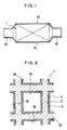
- the automotive vehicle is provided with an exhaust tube 10 for discharging exhaust gases from a combustion engine thereof and the exhaust tube 10 is provided with an exhaust system 12 which comprises a housing 14 connected to the exhaust tube 10 and a catalyst system for purifying exhaust gases disposed within the housing 14 comprising the catalyst 1 according to the present invention.
- the catalyst 1 comprises a catalyst carrier 2 and a coat comprised of a first coat layer 3 formed on a surface of the catalyst carrier 2 with a second coat layer 4 formed on a surface of the first coat layer 3.
- the catalyst carrier 2 may be of a honeycomb structure having a large number of pores 16 extending in the direction parallel to the passage of exhaust gases.
- the catalyst carrier 2 may include, for example, ceramics such as cordierite, heat-resistant metal, and heat-resistant inorganic fibers.
- the first coat layer 3 comprises active alumina as a major component and a catalyst component comprised of a noble metal which may be contained in a dispersed state in the active alumina and which may include, for example, platinum and rhodium.
- the second coat layer 4 may comprise cerium oxide as a major component, active alumina and palladium that in turn is immobilized on the cerium oxide. Further, barium oxide is immobilized on the cerium oxide particles and, if desried, lanthanum oxide may be immobilized on the cerium oxide particles, in addition to barium oxide.
- the catalyst 1 may be prepared in the following manner.
- An appropriate amount of gamma-aluminium oxide (Al2O3) may be admixed with appropriate amounts of boehmite, water and nitric acids, thereby forming a slurry.
- the catalyst carrier 2 may then be taken from the slurry and a surplus of the slurry on the surface of the catalyst carrier 2 may be removed by air blowing, thereby giving the catalyst carrier 2 with the slurry coated to the surface thereof as a wash coat.
- the carrier 2 with the slurry may be dried at elevated temperature for an appropriate period of time and then calcined for an appropriate time period at a temperature higher than the temperature at which the carrier 2 with the slurry has been dried, thereby providing the catalyst carrier 2 with the first coat layer 3 formed on the surface thereof.
- the catalyst carrier 2 with the first coat layer 3 may then be impregnated with a solution containing a noble metal compound, thereby depositing the noble metal on the first coat layer 3 as the catalyst component.
- a noble metal compound may be appropriately selected a platinum compound and a rhodium compound.
- the platinum compound there may be employed any one that can exhibit the activity of purifying exhaust gases when deposited on the catalyst carrier and may include, for example, Pt(NO2)2(NH3)2, platinum chloride, and so on.
- the rhodium compound may include, for example, rhodium nitrate and so on, although any rhodium compound may be used for this purpose as long as it can demonstrate the function of removing hazardous components from exhaust gases when deposited on the catalyst carrier.
- the catalyst carrier 2 with its first coat layer 3 may be dried for an appropriate period of time at elevated temperature and then calcined for an appropriate time period at a temperature higher than the temperature at which the catalyst carrier 2 with the first coat layer 3 has been dried, thereby depositing the noble metal on the first coat layer 3 as the catalyst component.
- the amount of the alumina in the first coat layer 3 may appropriately range from 2% to 10% by weight with respect to the weight of the catalyst carrier 2 and the amount of the noble metal to be deposited on the first coat layer be above approximately 1.0 grams per liter.
- cerium oxide (CeO2) and boehmite are admixed with barium nitrate [Ba(NO3 ) 2] in appropriate amounts and the mixture may be dried to form a solid mass which in turn may be pulverized into finely divided particles having an average particle size of 100 Angstroms or smaller, preferably ranging from 50 to 100 Angstroms. It is to be noted herein that the barium is immobilized on the particles of the cerium oxide.
- the resulting powders may then be admixed with an aqueous of palladium chloride, resulting in a slurry in which the catalyst carrier 2 with the first coat layer 3 may in turn be immersed to thereby form a second coat layer 4 on the surface of the first coat layer 3.
- the carrier 2 may be dried for an appropriate period of time at elevated temperature and then calcined for an appropriate period of time at a temperature higher than the temperature at which the carrier 2 has been dried, thereby yielding the catalyst carrier 2 with the second coat layer 4 formed on the surface of the first coat layer 3 and converting the immobilized barium into barium oxide.
- the amount of the wash coat in the second coat layer 4 may vary with respect to the weight of the catalyst carrier 2 and the amount of palladium deposited may be above 0.5 gram per liter.
- the amount of the barium oxide to be immobilized may vary and range usually from 1% to 15% by weight, preferably from 1% to 10% by weight, with respect to the amount of a total wash coat of the first coat layer 3 and the second coat layer 4, and the amount of the cerium oxide may range usually from 2% to 45% by weight, preferably from 5% to 30% by weight, with respect to the total weight of the first coat layer 3 and the second coat layer 4.
- the barium oxide immobilized on the cerium oxide particles can suppress the particles of the cerium oxide from aggregating with each other and enlarging their particles, thereby enabling a prevention of the growth of crystals of the cerium oxide upon exposure to exhaust gases having high temperatures.
- a very large number of pores formed in the cerium oxide crystals can serve as rendering the crystals of the cerium oxide denser and more tight due to the lattice dispersion of barium ions, so that the migration or distortion of the lattice of the cerium oxide is suppressed, thereby preventing the particles of the cerium oxide from growing and enlarging and, consequently, suppressing heat deterioration exerting adverse impacts on the ability of purifying exhaust gases and stabilizing the catalytic activity at low temperatures as well as improving heat resistance of the catalyst.
- the rhodium having heat resistance may be interposed among the platinum, thereby preventing the platinum from sintering and suppressing heat deterioration of the platinum.
- the deposition of the rhodium can also serve as suppressing heat deterioration of the catalyst itself.
- the catalyst carrier 2 with the base coat layer was then impregnated with a solution containing a platinum compound as represented by formula: Pt(NO2)2(NH3)2, and rhodium nitrate.
- the catalyst carrier 2 with its first coat layer 3 was dried at 200°C for 1 hour and then calcined at 600 °C for 2 hours to thereby form the first coat layer 3.
- the amount of the alumina (the amount of a wash coat) was varied from 2% to 10% by weight with respect to the weight of the catalyst carrier 2, and the total amount of the noble metal deposited was 1.6 grams per liter with the ratio of platinum to rhodium of 5 to 1.
- the resulting powders were then admixed with a solution of palladium chloride and 240 ml of water, resulting in a slurry in which the catalyst carrier 2 with the first coat layer 3 was in turn immersed to thereby form a second coat layer 4 on the surface of the first coat layer 3.
- the carrier 2 was dried at 130°C for 1 hour and then calcined at 550°C for 1.5 hours, thereby converting the barium immobilized on the particles of the cerium oxide into barium oxide.
- the amount of a wash coat of the second coat layer 4 was found to be 14% by weight with respect to the weight of the catalyst carrier 2, and the amount of palladium deposited was 1.0 grams per liter.
- the catalyst was prepared in substantially the same manner as in Example A except for the addition of a solution of lanthanum nitrate, together with the barium nitrate, in such an amount as to account for 5% by weight as lanthanum oxide with respect to the weight of a total wash coat of the first and second coat layers 3 and 4.
- the rate in weight of the cerium oxide contained in the second coat layer 4 to the active alumina contained in the second coat layer 4 may range from approximately 95 to 5 to approximately 70 to 30. If the amount of the cerium oxide would be too much, the catalytic activity may be improved whereas it may become likely to come off and its durability may be reduced. On the other hand, a too small amount of the cerium oxide may reduce the activity of removing CO from exhaust gases.
- a mixture of 100 grams of gamma-aluminium oxide and 100 grams of boehmite was admixed with 240 ml of water, 1 ml of nitric acid and 60 grams of cerium oxide, thereby forming a slurry.
- a lanthanum nitrate solution and a barium nitrate solution so as to allow a total weight of the wash coat to account for 21% by weight with respect to the weight of the catalyst carrier in a honeycomb structure to thereby form an alumina slurry.
- this slurry was immersed the catalyst carrier, and the carrier was taken from the slurry followed by removing a surplus of the slurry by means of air blowing.
- the carrier was dried at 130°C for 1 hour and calcined at 550°C for 1.5 hours. Thereafter, the carrier was immersed in a solution containing given concentrations of platinum, rhodium and palladium. The immersed carrier was then dried at 200°C for 1 hour and calcined at 600 °C for 2 hours, thereby yielding the catalyst containing each 5% by weight as lanthanum oxide and barium oxide with respect to the weight of the wash coat.
- a mixture of 100 grams of gamma-aluminium oxide and 100 grams of boehmite was admixed with 240 ml of water and 1 ml of nitric acid, thereby forming a slurry in which the catalyst carrier 2 was immersed, and the carrier was taken from the slurry followed by removing a surplus of the slurry by means of air blowing. Then the carrier was dried at 130°C for 1 hour and calcined at 550°C for 1.5 hours. Thereafter, the resulting carrier was immersed in a solution of platinum chloride and rhodium chloride and it was then driedat 200 °C for 1 hour followed by calcining it at 600°C for 2 hours, thereby forming the first coat layer.
- the amount of the alumina (the amount of a wash coat) in the first coat layer was found to be 7% by weight based on the weight of the carrier, and the amount of the noble metals deposited was found to be 1.6 grams per liter (a Pt:Rh ratio being 5 : 1).
- Example A The catalyst obtained in Example A and the catalysts obtained in Comparative Examples 1 and 2 were tested for ability of removing hydrocarbons from exhaust gases.
- each of the catalysts was filled in the amount of 24 ml and aged for 50 hours at the air temperature of 900 °C .
- the exhaust gases used for the test were passed through the catalyst at a space velocity of 60,000 hour ⁇ 1 under the air/fuel ratio of 14.7.
- the HC purification ratios were measured by varying the temperature of the exhaust gases at the inlet portion of the catalyst.
- the test results areshown in FIG. 4. As is apparent from the test results as shown in FIG. 4, it is found that the catalyst according to the present invention has shown its catalytic activity of purifying the exhaust gases at temperatures lower than the temperatures at which the catalysts according to the comparative examples have shown, thereby suppressing heat deterioration and improving heat resistance.
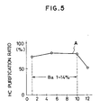
- the catalyst was prepared in substantially the same manner as in Example A except for the use of a solution containing varying amounts of barium oxide.
- the tests made in the same manner as described hereinabove have revealed the results of removal of hydrocarbons as shown by line A in FIG. 5 in the same manner as tested hereinabove.
- Example B The procedure of Example B above was repeated except for using varying amounts of lanthanum nitrate, thereby producing the catalysts having 1% by weight of the barium oxide, 14% by weight of the cerium oxide, and lanthanum oxide in the amounts ranging from 1% to 10% by weight (1%, 5% and 10% by weight, in this example), as indicated by circles on the line B in FIG. 6.
- Example B The procedure of Example B above was repeated except for using varying amounts of lanthanum nitrate, thereby producing the catalysts having 5% by weight of the barium oxide, 14% by weight of the cerium oxide, and lanthanum oxide in the amounts ranging from 1% to 10% by weight (1%, 5% (Example B) and 10% by weight, in this example), as indicated by triangles on the line C in FIG. 6.
- Example B The procedure of Example B above was repeated except for using varying amounts of lanthanum nitrate, thereby producing the catalysts having 10% by weight of the barium oxide, 14% by weight of the cerium oxide, and lanthanum oxide in the amounts ranging from 1% to 10% by weight (1%, 5% and 10% by weight, in this example), as indicated by squares on the line D in FIG. 6.
- Example 2 The procedure of Example 2 above was repeated except for using the appropriate amount of lanthanum nitrate, thereby producing the catalysts having 1% by weight of the barium oxide, 14% by weight of the cerium oxide, and 12% by weight of lanthanum oxide, as indicated by the circle on the line B in FIG. 6.
- Example 3 The procedure of Example 3 above was repeated except for using the appropriate amount of lanthanum nitrate, thereby producing the catalysts having 5% by weight of the barium oxide, 14% by weight of the cerium oxide, and 12% by weight of lanthanum oxide, as indicated by the triangle on the line C in FIG. 6.
- Example 4 The procedure of Example 4 above was repeated except for using the appropriate amount of lanthanum nitrate, thereby producing the catalysts having 10% by weight of the barium oxide, 14% by weight of the cerium oxide, and 12% by weight of lanthanum oxide, as indicated by the square on the line D in FIG. 6.
- the catalysts obtained in Examples 2 to 4 and in Comparative Examples 3 to 5 were tested for their activities for removing hydrocarbon from exhaust gases in the same manner as described hereinabove.
- the test results are shown in FIG. 6.
- the preferred range of the amount of the lanthanum oxide to be contained in the catalyst may be determined to be from 1% to 10% by weight with respect to the weight of a total wash coat of the first coat layer 3 and the second coat layer 4.
- Example B The procedure of Example B above was repeated except for using varying amounts of barium nitrate, thereby producing the catalysts having 1% by weight of the lanthanum oxide, 14% by weight of the cerium oxide, and barium oxide in the amounts ranging from 1% to 10% by weight (1%, 5% and 10% by weight, in this example), as indicated by circles on the line E in FIG. 7.
- Example B The procedure of Example B above was repeated except for using varying amounts of barium nitrate, thereby producing the catalysts having 5% by weight of the lanthanum oxide, 14% by weight of the cerium oxide, and barium oxide in the amounts ranging from 1% to 10% by weight (1%, 5% and 10% by weight, in this example), as indicated by triangles on the line F in FIG. 7.
- Example B The procedure of Example B above was repeated except for using varying amounts of barium nitrate, thereby producing the catalysts having 10% by weight of the lanthanum oxide, 14% by weight of the cerium oxide, and barium oxide in the amounts ranging from 1% to 10% by weight (1%, 5% and 10% by weight, in this example), as indicated by squares on the line G in FIG. 7.
- Example 5 The procedure of Example 5 above was repeated except for using the appropriate amount of barium nitrate, thereby producing the catalysts having 1% by weight of the lanthanum oxide, 14% by weight of the cerium oxide, and 12% by weight of barium oxide, as indicated by the circle on the line E in FIG. 7.
- Example 6 The procedure of Example 6 above was repeated except for using the appropriate amount of barium nitrate, thereby producing the catalysts having 5% by weight of the lanthanum oxide, 14% by weight of the cerium oxide, and 12% by weight of barium oxide, as indicated by the triangle on the line F in FIG. 7.
- Example 7 The procedure of Example 7 above was repeated except for using the appropriate amount of barium nitrate, thereby producing the catalysts having 10% by weight of the lanthanum oxide, 14% by weight of the cerium oxide, and 12% by weight of barium oxide, as indicated by the square on the line G in FIG. 7.
- the catalysts obtained in Examples 5 to 10 were tested for their activities for removing hydrocarbon from exhaust gases in the same manner as described hereinabove.
- the test results are shown in FIG. 7.
- the preferred range of the amount of the barium oxide to be contained in the catalyst may be determined to be from 1% to 10% by weight with respect to the weight of a total wash coat of the first coat layer 3 and the second coat layer 4, although a more amount of the barium oxide can perform the HC purification activity higher than the catalyst containing no barium oxide and such an amount of the barium oxide should be noted to be still contained in the scope of the invention.
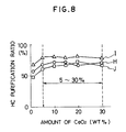
- Example B The procedure of Example B above was repeated except for using varying amounts of cerium oxide, thereby producing the catalysts having 1% by weight each of the barium oxide and the lanthanum oxide and barium oxide in the amounts ranging from 5% to 30% by weight (5%, 10%, 14%, 20% and 30% by weight, in this example), as indicated by circles on the line H in FIG. 8.
- Example B The procedure of Example B above was repeated except for using varying amounts of cerium oxide, thereby producing the catalysts having 5% by weight each of the barium oxide and the lanthanum oxide and cerium oxide in the amounts ranging from 5% to 30% by weight (5%, 10%, 14%, 20% and 30% by weight, in this example), as indicated by triangles on the line I in FIG. 8.
- Example B The procedure of Example B above was repeated except for using varying amounts of cerium oxide, thereby producing the catalysts having 10% by weight each of the barium oxide and the lanthanum oxide and cerium oxide in the amounts ranging from 5% to 30% by weight (5%, 10%, 14%, 20% and 30% by weight, in this example), as indicated by squares on the line J in FIG. 8.
- Example 8 The procedure of Example 8 above was repeated except for using the appropriate cerium oxide, thereby producing the catalyst having 1% by weight of the barium oxide and lanthanum oxide and 1% of cerium oxide, as indicated by circle on the line H in FIG. 8.
- Example 9 The procedure of Example 9 above was repeated except for using the appropriate cerium oxide, thereby producing the catalyst having 5% by weight of the barium oxide and lanthanum oxide and 1% of cerium oxide, as indicated by triangle on the line I in FIG. 8.
- Example 10 The procedure of Example 10 above was repeated except for using the appropriate cerium oxide, thereby producing the catalyst having 10% by weight of the barium oxide and lanthanum oxide and 1% of cerium oxide, as indicated by square on the line J in FIG. 8.
- the catalysts obtained in Examples 11 to 13 and in Comparative Examples 6 to 8 were tested for their activities for removing hydrocarbon from exhaust gases in the same manner as described hereinabove.
- the test results are shown in FIG. 8.
- the preferred range of the amount of the cerium oxide to be contained in the catalyst may be determined to be preferably from 5% to 30% by weight with respect to the weight of the catalyst carrier and the first coat layer 3, although the amount of the cerium oxide may generally range from 2% to 45% by weight.
- the gasoline currently in use as a fuel for automotive vehicles contains the sulfur component which in turn is converted into sulfur dioxide by combustion. Hence, sulfur dioxide is contained in exhaust gases.
- the sulfur dioxide reacts with hydrogen H2 in the catalyst in the manner as described hereinafter. SO2 + H2 ⁇ H2S + O2 (1)
- sulfur hydrogen so produced is noxious and extremely malodorous, demands have been made to suppress the generation of sulfur hydrogen from the catalyst.
- the sulfur dioxide is trapped with a metal M in the catalyst and stored in the form of a metal salt MSO4.
- the stored sulfur dioxide may be freed from the metal salt when the air/fuel ratio is turned from its lean atmosphere to its rich atmosphere and discharged as hydrogen sulfide.
- hydrogen sulfur is temporarily discharged in a large amount, its malodor becomes intoreably remarkable and causes various problems.
- metal salt MSO4 may be formed in the following way, too. MO + SO2 + 1/202 ⁇ MSO4 (4)
- the metal salt MSO4 may be in the form as represented by aluminium sulfite, i.e., Al2(SO4)3, or cerium sulfite, i.e., Ce2 (SO4)2.
- the metal salt MSO4 once stored in the catalyst is converted into hydrogen sulfide H2S in the manner as represented by the formula (5) below, when exhaust gases are turned from oxidation atmosphere to reduction atmosphere, and the hydrogen sulfide so generated is discharged in a large quantity, although temporarily.
- FIG. 9 shows the relationship of the amounts of hydrogen sulfide with changes of exhaust gases in the air/fuel ratios. More specifically, as shown in FIG. 9, in such a state that the automotive vehicle is running in a stationary running mode in the oxidative atmosphere wherein the air/fuel ratio is 16.0, the sulfur dioxide in the exhaust gases is stored in the form of the metal salt MSO4 in the catalyst. And when the stationary running state is changed to an idling state in which the automotive vehicle is suspended, the oxidation atmosphere is also turned into the reduction atmosphere in which the air/fuel ratio is 13.5.
- the technique of trapping hydrogen sulfide adopted in the measure applied to the automotive vehicles for suppressing the formation of hydrogen sulfide involves using nickel as a component for the catalyst.
- This technique can trap hydrogen sulfide as nickel sulfide by allowing the hydrogen sulfide to be exposed to the nickel in the presence of cerium oxide in an atomosphere in which the air/fuel ratio is rich, namely, in the reduction atmosphere.
- the catalyst 5 according to the second embodiment of the present invention comprises a catalyst carrier 6 having a large number of pores 16 passing through the entire thickness of the carrier and extending in a direction parallel to the direction of passage of exhaust gases.
- a coat layer 7 comprised of cerium oxide (CeO2) is provided on inner surfaces over the entire length of the fine pores 16 formed in the catalyst carrier 6.
- the coat layer 7 is comprised mainly of active alumina Al2O3 in which a catalyst component consisting of a noble metal and barium oxide are contained.
- the catalyst component is present in the active alumina in a dispersed state, and at least one of platinum and rhodium is contained as the catalyst component.
- the catalyst carrier 6 of a honeycomb structure Into the slurry was immersed the catalyst carrier 6 of a honeycomb structure, and the catalyst carrier 6 was taken from the slurry followed by removing a surplus of the slurry from the carrier by means of air blowing.
- the carrier 6 with the slurry adhering thereto was dried at 600 °C for 1 hour and then the carrier 6 was calcined at the temperature of 550°C and in the oxidation atmosphere, thereby resulting in the formation of a coat layer. This treament allowed the barium immobilized on the cerium oxide to react with oxygen converting into barium oxide.
- the resulting catalyst carrier 6 having the alumina layer with the barium oxide immobilized thereon was then immersed in a solution of appropriate amounts of platinum chloride and rhodium chloride in 170 ml of water, and the immersed carrer was taken from the solution followed by removing a surplus of the solution containing the noble metal compounds by means of air blowing. Thereafter, the resulting catalyst carrier 6 was calcined at 600°C for 2 hours, thereby forming the coat layer 7.
- the resulting coat layer 7 contained the alumina in the amount (as an amount of the wash coat) of 28% by weight with respect to the weight of the catalyst carrier 6, and the cerium oxide was contained in the amount of 40% by weight with respect to the weight of the wash coat while the barium oxide was contained in the amount of 2.5% by weight (3.0 grams per liter) with respect to the weight of the wash coat.
- the amounts of platinum and rhodium were 1.0 grams per liter and 0.2 gram per liter, respectively.
- the catalyst was prepared in substantially the same manner as in Example 11 except for the use of barium oxide so as to allow the barium oxide to be immobilized on the cerium oxide in the amount of 3.3% by weight with respect to the weight of the wash coat.
- the catalyst was prepared in substantially the same manner as in Example 11 except for the use of barium oxide so as to allow the barium oxide to be immobilized on the cerium oxide in the amount of 5.8% by weight with respect to the weight of the wash coat.
- the catalyst was prepared in substantially the same manner as in Example 11 except for the use of barium oxide so as to allow the barium oxide to be immobilized on the cerium oxide in the amount of 7.5% by weight with respect to the weight of the wash coat.
- the catalyst was prepared in substantially the same manner as in Example 11 except for the use of barium oxide so as to allow the barium oxide to be immobilized on the cerium oxide in the amount of 11.7% by weight with respect to the weight of the wash coat.
- the catalyst was prepared in substantially the same manner as in Example 11 except for the use of barium oxide so as to allow the barium oxide to be immobilized on the cerium oxide in the amount of 13.3% by weight with respect to the weight of the wash coat.
- the catalyst was prepared in substantially the same manner as in Example 11 except for no use of barium oxide.
- the catalysts so prepared were then tested for a variation in the amounts of hydrogen sulfide formed with lapse of the time period, namely, with changes in the air/fuel ratios.
- exhaust gases having the air/fuel ratio of 13.5 started discharging in the period (1) during which the temperature of the exhaust gases were elevated to 500 °C .
- the air/fuel ratio was raised to 16.0 in order to bring the air/fuel ratio into the oxidation atmosphere.
- the air/fuel ratio was lowered to 13.5 and brought into the reduction atmosphere, thereby causing hydrogen sulfide.
- the maximum concentrationof hydrogen sulfide discharged in the period (3) was measured.
- the catalysts to be tested were aged in the atmosphere having the temperature of 900°C for 50 hours prior to testing. Then they were tested for its HC purification ratio at the temperature of 400 °C at the inlet portion of the catalyst system in the atmosphere of the air/fuel ratio being 14.5 at the space velocity of 60,000 hour ⁇ 1.
- the catalysts prepared in Examples 11 to 16 reduced the amount of hydrogen sulfide formed below approximately 50 ppm, while the catalyst prepared in Comparative Example 12 produced hydrogen sulfide in the amount as high as 100 ppm.
- the catalyst according to the present invention reduced the formation of hydrogen sulfide as low as half or less that formed by the catalyst without any barium oxide immobilized.
- the catalyst prepared in Examples 11 to 16 exhibited the ability of purifying exhaust gases, i.e., removing hydrocarbons from exhaust gases, higher than the catalyst prepared in Comparative Example 12 in which no barium oxide was immobilized.
- the test results as shown in FIG. 12 reveals that the catalyst according to the second embodiment of the present invention may preferably contain the barium oxide in the range generally from 1% to 15% by weight, preferably from 3% to 13% by weight.
- barium oxide is considered to be converted into barium sulfide BaS by reaction with cerium sulfite, Ce2(SO4)2, in the following formula (6), thereby forming no hydrogen sulfide.
- the barium sulfide BaS so preduced is reacted with oxygen in the follwoing reaction formula (7) to give barium sulfate, producing no cerium sulfite Ce2(SO4)2 and suppressing the storage of sulfur dioxide.
- the catalyst 5 according to the second embodiment of the present invention has the coat layer 7 comprising cerium oxide, barium oxide immobilized on the cerium oxide, active alumina, and the catalyst component comprised of platinum and/or rhodium.
- the present invention can provide the catalyst by using harmless barium, thereby trapping hazardous sulfur components in the catalyst and suppressing the generation of malodorous hydrogen sulfide, without the use of nickel.
Landscapes
- Chemical & Material Sciences (AREA)
- Engineering & Computer Science (AREA)
- Chemical Kinetics & Catalysis (AREA)
- Organic Chemistry (AREA)
- Materials Engineering (AREA)
- Health & Medical Sciences (AREA)
- Analytical Chemistry (AREA)
- General Chemical & Material Sciences (AREA)
- Oil, Petroleum & Natural Gas (AREA)
- Environmental & Geological Engineering (AREA)
- Biomedical Technology (AREA)
- Combustion & Propulsion (AREA)
- Catalysts (AREA)
- Exhaust Gas Treatment By Means Of Catalyst (AREA)
Applications Claiming Priority (4)
| Application Number | Priority Date | Filing Date | Title |
|---|---|---|---|
| JP17481989 | 1989-07-06 | ||
| JP174819/89 | 1989-07-06 | ||
| JP76731/90 | 1990-03-28 | ||
| JP07673190A JP3285857B2 (ja) | 1989-07-06 | 1990-03-28 | 排気ガス浄化用触媒 |
Publications (3)
| Publication Number | Publication Date |
|---|---|
| EP0407915A2 true EP0407915A2 (fr) | 1991-01-16 |
| EP0407915A3 EP0407915A3 (en) | 1992-03-18 |
| EP0407915B1 EP0407915B1 (fr) | 1994-06-08 |
Family
ID=26417865
Family Applications (1)
| Application Number | Title | Priority Date | Filing Date |
|---|---|---|---|
| EP90112951A Expired - Lifetime EP0407915B1 (fr) | 1989-07-06 | 1990-07-06 | Catalyseur pour la purification de gaz d'échappement |
Country Status (4)
| Country | Link |
|---|---|
| US (1) | US5075275A (fr) |
| EP (1) | EP0407915B1 (fr) |
| JP (1) | JP3285857B2 (fr) |
| DE (1) | DE69009601T2 (fr) |
Cited By (7)
| Publication number | Priority date | Publication date | Assignee | Title |
|---|---|---|---|---|
| EP0716876A1 (fr) * | 1994-12-16 | 1996-06-19 | Toyota Jidosha Kabushiki Kaisha | Catalyseur pour la purification de gaz d'échappement |
| US6149877A (en) * | 1997-01-21 | 2000-11-21 | Toyota Jidosha Kabushiki Kaisha | Exhaust gas purifying catalyst |
| WO2002055181A1 (fr) * | 2001-01-11 | 2002-07-18 | Delphi Technologies, Inc. | Procedes permettant de reduire la migration de materiau alcalin de la couche d'adsorption vers la cordierite |
| EP1205236A3 (fr) * | 2000-11-09 | 2002-11-13 | Nissan Motor Co., Ltd. | Catalyseur pour la purification de gaz d'échappement et procédé pour sa fabrication |
| US7323432B2 (en) * | 2002-08-22 | 2008-01-29 | Denso Corporation | Catalyst assembly |
| WO2014164876A1 (fr) * | 2013-03-13 | 2014-10-09 | Basf Corporation | Catalyseur de stockage de nox présentant une stabilité hydrothermique améliorée et un taux de conversion des nox amélioré |
| US9611774B2 (en) | 2013-03-13 | 2017-04-04 | Basf Corporation | Catalyst with improved hydrothermal stability |
Families Citing this family (36)
| Publication number | Priority date | Publication date | Assignee | Title |
|---|---|---|---|---|
| US5200382A (en) * | 1991-11-15 | 1993-04-06 | Exxon Research And Engineering Company | Catalyst comprising thin shell of catalytically active material bonded onto an inert core |
| US5212130A (en) * | 1992-03-09 | 1993-05-18 | Corning Incorporated | High surface area washcoated substrate and method for producing same |
| JP3311012B2 (ja) * | 1992-03-23 | 2002-08-05 | 株式会社豊田中央研究所 | 排気ガス浄化用触媒および排気ガス浄化方法 |
| JP3145175B2 (ja) * | 1992-03-31 | 2001-03-12 | 三井金属鉱業株式会社 | 排ガス浄化用触媒及びその製造方法 |
| US6010673A (en) * | 1992-09-21 | 2000-01-04 | Toyota Jidosha Kabushiki Kaisha | Method for purifying exhaust gas |
| EP0613714B1 (fr) * | 1993-01-11 | 2001-07-04 | Toyota Jidosha Kabushiki Kaisha | Procédé pour la purification de gaz d'échappements |
| JP3291086B2 (ja) * | 1993-09-24 | 2002-06-10 | トヨタ自動車株式会社 | 排ガス浄化用触媒及び排ガス浄化方法 |
| JP3409894B2 (ja) * | 1993-11-17 | 2003-05-26 | トヨタ自動車株式会社 | 排ガス浄化用触媒及び排ガス浄化方法 |
| US5968462A (en) * | 1994-02-04 | 1999-10-19 | Toyota Jidosha Kabushiki Kaisha | Process for purifying exhaust gases |
| JP3353480B2 (ja) * | 1994-08-23 | 2002-12-03 | 日産自動車株式会社 | 排気ガス浄化用触媒システム |
| US6165933A (en) * | 1995-05-05 | 2000-12-26 | W. R. Grace & Co.-Conn. | Reduced NOx combustion promoter for use in FCC processes |
| US6129834A (en) * | 1995-05-05 | 2000-10-10 | W. R. Grace & Co. -Conn. | NOx reduction compositions for use in FCC processes |
| US5874057A (en) * | 1995-07-12 | 1999-02-23 | Engelhard Corporation | Lean NOx catalyst/trap method |
| US5750082A (en) * | 1995-09-21 | 1998-05-12 | Ford Global Technologies, Inc. | Nox trap with improved performance |
| JPH09262471A (ja) * | 1996-03-29 | 1997-10-07 | Tokyo Roki Kk | 排気ガス浄化用触媒材料、排気ガス浄化用触媒及びその製造方法 |
| JP4029233B2 (ja) * | 1998-05-11 | 2008-01-09 | 第一稀元素化学工業株式会社 | セリウム−ジルコニウム系複合酸化物及びその製造方法ならびに排ガス浄化用触媒材料 |
| US6479428B1 (en) * | 1998-07-27 | 2002-11-12 | Battelle Memorial Institute | Long life hydrocarbon conversion catalyst and method of making |
| DE19847008A1 (de) * | 1998-10-13 | 2000-04-20 | Degussa | Stickoxid-Speicherkatalysator |
| US6497848B1 (en) | 1999-04-02 | 2002-12-24 | Engelhard Corporation | Catalytic trap with potassium component and method of using the same |
| JP4548968B2 (ja) * | 2000-06-05 | 2010-09-22 | 株式会社日本自動車部品総合研究所 | セラミック担体およびセラミック触媒体 |
| EP1318728A2 (fr) * | 2000-09-18 | 2003-06-18 | Rothmans, Benson & Hedges Inc. | Cigarette a faible induction de tabagisme passif a materiau traitant non combustible |
| FI20010973A7 (fi) * | 2001-05-09 | 2002-11-10 | Valtion Teknillinen Tutkimuskeskus | Katalysaattori ja menetelmä typpioksidien katalyyttiseksi pelkistämiseksi |
| KR100405470B1 (ko) * | 2001-06-27 | 2003-11-14 | 현대자동차주식회사 | 디젤엔진용 산화촉매 조성물 |
| KR20030004732A (ko) * | 2001-07-06 | 2003-01-15 | 현대자동차주식회사 | Cng 자동차 배기가스 정화용 촉매 및 이의 제조방법 |
| NZ531553A (en) * | 2001-09-13 | 2005-09-30 | Rothmans Benson & Hedges | Zirconium/metal oxide fibres |
| US7390768B2 (en) * | 2002-01-22 | 2008-06-24 | The United States Of America As Represented By The Administrator Of The National Aeronautics And Space Administration | Stabilized tin-oxide-based oxidation/reduction catalysts |
| US20050205465A1 (en) * | 2002-02-22 | 2005-09-22 | Peters Alan W | NOx reduction compositions for use in FCC processes |
| DE102004043421A1 (de) * | 2004-09-06 | 2006-03-23 | W.C. Heraeus Gmbh | Katalysator für 2-Takt-Motoren oder Kleinmotoren |
| JP5000221B2 (ja) * | 2006-07-14 | 2012-08-15 | 本田技研工業株式会社 | 排ガス浄化触媒及び排ガス浄化装置 |
| JP2008023501A (ja) * | 2006-07-25 | 2008-02-07 | Toyota Motor Corp | 排ガス浄化用触媒 |
| US20080120970A1 (en) | 2006-11-29 | 2008-05-29 | Marcus Hilgendorff | NOx Storage Materials and Traps Resistant to Thermal Aging |
| US8475752B2 (en) * | 2008-06-27 | 2013-07-02 | Basf Corporation | NOx adsorber catalyst with superior low temperature performance |
| BRPI0805625A2 (pt) | 2008-12-29 | 2010-09-14 | Petroleo Brasileiro Sa | catalisadores heterogêneos para a transesterificação de triglicerìdeos e métodos preparatórios dos mesmos |
| DE102013207709A1 (de) * | 2013-04-26 | 2014-10-30 | Umicore Ag & Co. Kg | Entschwefelung von NOX-Speicherkatalysatoren |
| CN106794447A (zh) * | 2014-08-25 | 2017-05-31 | 巴斯夫公司 | 具有改进的水热稳定性的催化剂 |
| GB201616812D0 (en) | 2016-10-04 | 2016-11-16 | Johnson Matthey Public Limited Company | NOx adsorber catalyst |
Family Cites Families (9)
| Publication number | Priority date | Publication date | Assignee | Title |
|---|---|---|---|---|
| CA1213874A (fr) * | 1983-05-12 | 1986-11-12 | Tomohisa Ohata | Obtention d'un catalyseur alveolaire pour la conversion des gaz d'echappement |
| FR2546078B1 (fr) * | 1983-05-19 | 1987-05-07 | Pro Catalyse | Procede de fabrication de catalyseurs pour le traitement des gaz d'echappement des moteurs a combustion interne |
| GB2142253A (en) * | 1983-06-27 | 1985-01-16 | Johnson Matthey Plc | Exhaust gas purification catalysts |
| JPS60200021A (ja) * | 1984-03-26 | 1985-10-09 | Toshiba Corp | ガスタ−ビン燃焼器 |
| US4624940A (en) * | 1985-04-12 | 1986-11-25 | Engelhard Corporation | High temperature catalyst compositions for internal combustion engine |
| US4727052A (en) * | 1986-06-27 | 1988-02-23 | Engelhard Corporation | Catalyst compositions and methods of making the same |
| JPH0626672B2 (ja) * | 1987-03-05 | 1994-04-13 | 株式会社豊田中央研究所 | 排気浄化触媒及びその製造方法 |
| JP2537239B2 (ja) * | 1987-08-28 | 1996-09-25 | エヌ・イーケムキヤツト 株式会社 | 耐熱性に優れた内燃機関排気ガス浄化用触媒及びその製造方法 |
| US4782038C1 (en) * | 1987-10-26 | 2001-04-17 | Ford Motor Co | Platinum group alumina-supported metal oxidation catalysts and method of making same |
-
1990
- 1990-03-28 JP JP07673190A patent/JP3285857B2/ja not_active Expired - Fee Related
- 1990-07-06 EP EP90112951A patent/EP0407915B1/fr not_active Expired - Lifetime
- 1990-07-06 DE DE69009601T patent/DE69009601T2/de not_active Expired - Fee Related
- 1990-07-06 US US07/548,707 patent/US5075275A/en not_active Expired - Lifetime
Cited By (11)
| Publication number | Priority date | Publication date | Assignee | Title |
|---|---|---|---|---|
| EP0716876A1 (fr) * | 1994-12-16 | 1996-06-19 | Toyota Jidosha Kabushiki Kaisha | Catalyseur pour la purification de gaz d'échappement |
| US5702675A (en) * | 1994-12-16 | 1997-12-30 | Toyota Jidosha Kabushiki Kaisha | Catalyst for purifying exhaust gases and process for producing the same |
| US6149877A (en) * | 1997-01-21 | 2000-11-21 | Toyota Jidosha Kabushiki Kaisha | Exhaust gas purifying catalyst |
| EP1205236A3 (fr) * | 2000-11-09 | 2002-11-13 | Nissan Motor Co., Ltd. | Catalyseur pour la purification de gaz d'échappement et procédé pour sa fabrication |
| US7169734B2 (en) | 2000-11-09 | 2007-01-30 | Nissan Motor Co., Ltd. | Exhaust gas purifying catalyst and method of producing same |
| WO2002055181A1 (fr) * | 2001-01-11 | 2002-07-18 | Delphi Technologies, Inc. | Procedes permettant de reduire la migration de materiau alcalin de la couche d'adsorption vers la cordierite |
| US7323432B2 (en) * | 2002-08-22 | 2008-01-29 | Denso Corporation | Catalyst assembly |
| WO2014164876A1 (fr) * | 2013-03-13 | 2014-10-09 | Basf Corporation | Catalyseur de stockage de nox présentant une stabilité hydrothermique améliorée et un taux de conversion des nox amélioré |
| KR20150131126A (ko) * | 2013-03-13 | 2015-11-24 | 바스프 코포레이션 | 개선된 열수 안정성 및 NOx 전환율을 갖는 NOx 저장 촉매 |
| US9611774B2 (en) | 2013-03-13 | 2017-04-04 | Basf Corporation | Catalyst with improved hydrothermal stability |
| US9610564B2 (en) | 2013-03-13 | 2017-04-04 | Basf Corporation | NOx storage catalyst with improved hydrothermal stability and NOx conversion |
Also Published As
| Publication number | Publication date |
|---|---|
| JPH03207446A (ja) | 1991-09-10 |
| JP3285857B2 (ja) | 2002-05-27 |
| EP0407915B1 (fr) | 1994-06-08 |
| EP0407915A3 (en) | 1992-03-18 |
| DE69009601D1 (de) | 1994-07-14 |
| US5075275A (en) | 1991-12-24 |
| DE69009601T2 (de) | 1994-09-22 |
Similar Documents
| Publication | Publication Date | Title |
|---|---|---|
| EP0407915B1 (fr) | Catalyseur pour la purification de gaz d'échappement | |
| US5063192A (en) | Catalyst for purification of exhaust gases | |
| US6066587A (en) | Catalyst for purifying exhaust gas | |
| EP0852966B1 (fr) | Catalyseur et méthode pour la purification de gaz d'échappement | |
| EP1008378B1 (fr) | Catalyseur pour la purification de gaz d'échappement | |
| KR960012096B1 (ko) | 내연기관 배기가스 처리용 촉매합성물 | |
| JP4098835B2 (ja) | 排気ガス浄化用触媒 | |
| CA2223458C (fr) | Catalyseur et processus d'epuration des gaz d'echappement | |
| US6191061B1 (en) | Method of purifying exhaust gas and catalyst for purifying exhaust gas | |
| JP3311012B2 (ja) | 排気ガス浄化用触媒および排気ガス浄化方法 | |
| EP0710499A2 (fr) | Nettoyeur de gaz d'échappement et méthode pour nettoyer un gaz d'échappement | |
| US6010673A (en) | Method for purifying exhaust gas | |
| KR20010053142A (ko) | 로듐, 지르코늄 및 희토류 산화물을 포함하는 배기가스 촉매 | |
| US6557342B2 (en) | Exhaust gas purifying system | |
| KR0172175B1 (ko) | 디젤 엔진용 배기 가스 정화 촉매 | |
| EP0589393B1 (fr) | Procédé pour purifier un gaz d'échappement riche en oxygène | |
| JP3436427B2 (ja) | 排ガス浄化用触媒及び排ガス浄化方法 | |
| JP3769803B2 (ja) | 排気ガス浄化用触媒 | |
| US20050170955A1 (en) | Exhaust gas purifying catalyst and method of producing same | |
| EP0377468B1 (fr) | Catalyseur de purification de gaz d'échappement supprimant la formation d'hydrogène sulfuré et procédé pour sa production | |
| US6296822B1 (en) | Process for manufacturing nox traps with improved sulfur tolerance | |
| WO2001014046A9 (fr) | Piege catalytique a composant au potassium et procede d'utilisation | |
| WO1993020937A1 (fr) | Dispositif servant a epurer des gaz d'echappement | |
| JPH07171349A (ja) | 排気ガス浄化方法 | |
| JP3377382B2 (ja) | ディーゼルエンジン用排ガス浄化用触媒 |
Legal Events
| Date | Code | Title | Description |
|---|---|---|---|
| PUAI | Public reference made under article 153(3) epc to a published international application that has entered the european phase |
Free format text: ORIGINAL CODE: 0009012 |
|
| AK | Designated contracting states |
Kind code of ref document: A2 Designated state(s): DE FR GB |
|
| PUAL | Search report despatched |
Free format text: ORIGINAL CODE: 0009013 |
|
| AK | Designated contracting states |
Kind code of ref document: A3 Designated state(s): DE FR GB |
|
| 17P | Request for examination filed |
Effective date: 19920602 |
|
| 17Q | First examination report despatched |
Effective date: 19921116 |
|
| GRAA | (expected) grant |
Free format text: ORIGINAL CODE: 0009210 |
|
| AK | Designated contracting states |
Kind code of ref document: B1 Designated state(s): DE FR GB |
|
| REF | Corresponds to: |
Ref document number: 69009601 Country of ref document: DE Date of ref document: 19940714 |
|
| ET | Fr: translation filed | ||
| PLBE | No opposition filed within time limit |
Free format text: ORIGINAL CODE: 0009261 |
|
| STAA | Information on the status of an ep patent application or granted ep patent |
Free format text: STATUS: NO OPPOSITION FILED WITHIN TIME LIMIT |
|
| 26N | No opposition filed | ||
| REG | Reference to a national code |
Ref country code: GB Ref legal event code: IF02 |
|
| PGFP | Annual fee paid to national office [announced via postgrant information from national office to epo] |
Ref country code: GB Payment date: 20030702 Year of fee payment: 14 |
|
| PGFP | Annual fee paid to national office [announced via postgrant information from national office to epo] |
Ref country code: FR Payment date: 20030711 Year of fee payment: 14 |
|
| PG25 | Lapsed in a contracting state [announced via postgrant information from national office to epo] |
Ref country code: GB Free format text: LAPSE BECAUSE OF NON-PAYMENT OF DUE FEES Effective date: 20040706 |
|
| GBPC | Gb: european patent ceased through non-payment of renewal fee |
Effective date: 20040706 |
|
| PG25 | Lapsed in a contracting state [announced via postgrant information from national office to epo] |
Ref country code: FR Free format text: LAPSE BECAUSE OF NON-PAYMENT OF DUE FEES Effective date: 20050331 |
|
| REG | Reference to a national code |
Ref country code: FR Ref legal event code: ST |
|
| PGFP | Annual fee paid to national office [announced via postgrant information from national office to epo] |
Ref country code: DE Payment date: 20060629 Year of fee payment: 17 |
|
| PG25 | Lapsed in a contracting state [announced via postgrant information from national office to epo] |
Ref country code: DE Free format text: LAPSE BECAUSE OF NON-PAYMENT OF DUE FEES Effective date: 20080201 |