EP0408008A2 - Sitzvorrichtung für einen Löffelbagger - Google Patents
Sitzvorrichtung für einen Löffelbagger Download PDFInfo
- Publication number
- EP0408008A2 EP0408008A2 EP90113270A EP90113270A EP0408008A2 EP 0408008 A2 EP0408008 A2 EP 0408008A2 EP 90113270 A EP90113270 A EP 90113270A EP 90113270 A EP90113270 A EP 90113270A EP 0408008 A2 EP0408008 A2 EP 0408008A2
- Authority
- EP
- European Patent Office
- Prior art keywords
- support post
- seat
- small size
- support
- seat device
- Prior art date
- Legal status (The legal status is an assumption and is not a legal conclusion. Google has not performed a legal analysis and makes no representation as to the accuracy of the status listed.)
- Granted
Links
Images

Classifications
-
- E—FIXED CONSTRUCTIONS
- E02—HYDRAULIC ENGINEERING; FOUNDATIONS; SOIL SHIFTING
- E02F—DREDGING; SOIL-SHIFTING
- E02F9/00—Component parts of dredgers or soil-shifting machines, not restricted to one of the kinds covered by groups E02F3/00 - E02F7/00
- E02F9/16—Cabins, platforms, or the like, for drivers
- E02F9/166—Cabins, platforms, or the like, for drivers movable, tiltable or pivoting, e.g. movable seats, dampening arrangements of cabins
-
- B—PERFORMING OPERATIONS; TRANSPORTING
- B60—VEHICLES IN GENERAL
- B60N—SEATS SPECIALLY ADAPTED FOR VEHICLES; VEHICLE PASSENGER ACCOMMODATION NOT OTHERWISE PROVIDED FOR
- B60N2/00—Seats specially adapted for vehicles; Arrangement or mounting of seats in vehicles
- B60N2/24—Seats specially adapted for vehicles; Arrangement or mounting of seats in vehicles for particular purposes or particular vehicles
- B60N2/38—Seats specially adapted for vehicles; Arrangement or mounting of seats in vehicles for particular purposes or particular vehicles specially constructed for use on tractors or like off-road vehicles
-
- E—FIXED CONSTRUCTIONS
- E02—HYDRAULIC ENGINEERING; FOUNDATIONS; SOIL SHIFTING
- E02F—DREDGING; SOIL-SHIFTING
- E02F3/00—Dredgers; Soil-shifting machines
- E02F3/04—Dredgers; Soil-shifting machines mechanically-driven
- E02F3/28—Dredgers; Soil-shifting machines mechanically-driven with digging tools mounted on a dipper- or bucket-arm, i.e. there is either one arm or a pair of arms, e.g. dippers, buckets
- E02F3/30—Dredgers; Soil-shifting machines mechanically-driven with digging tools mounted on a dipper- or bucket-arm, i.e. there is either one arm or a pair of arms, e.g. dippers, buckets with a dipper-arm pivoted on a cantilever beam, i.e. boom
- E02F3/32—Dredgers; Soil-shifting machines mechanically-driven with digging tools mounted on a dipper- or bucket-arm, i.e. there is either one arm or a pair of arms, e.g. dippers, buckets with a dipper-arm pivoted on a cantilever beam, i.e. boom working downwardly and towards the machine, e.g. with backhoes
- E02F3/325—Backhoes of the miniature type
Definitions
- This invention relates to a seat device for a very small size shovel car, and more particularly to a seat device for a very small shovel car wherein, when a seat is not used, it is retracted from a predetermined position so that it may not make an obstruction to an operation of the shovel car.
- a very small size shovel car has not be put into practical use which can be transported into a narrow alley or the like to perform civil engineering working such as ditch excavation.
- a cage should not be provided on such shovel car but a seat should provided at a rear portion of a car body of the shovel car in order to reduce the car body as small as possible.
- a seat device for a very small size shovel car wherein an operating boom is mounted for pivotal motion on a front portion of a car body while an engine and a transmission case are mounted on a rear portion of the car body, which comprises a support element mounted at a rear lower portion of the car body, a seat, a support post having the seat secured to the top end thereof, the support post being mounted on the support element for pivotal motion between an operative position in which the support post is directed upwardly rearwardly and a seat face of the seat is directed upwardly to allow an operator to be seated thereon and an inoperative position in which the support post extends vertically upwardly along the car body of the shovel car and the seat face of the seat is directed rearwardly, and securing means for securing the support post at the operative and inoperative positions.
- the support element for the support post for the seat is located at the rear lower portion of the car body of the very small size shovel car.
- the support post mounted on the support element extends rearwardly upwardly and is formed such that an operator may be seated on the seat mounted at the top end of the support post in order to operate the very small size shovel car.
- the support post can be pivoted forwardly from the operative position to the inoperative position in which it extends vertically upwardly along the car body and the seat is located near a rear portion of the car body and the seat face of the seat is directed rearwardly. At the inoperative position, the support post can be secured by the securing means.
- the support post may be mounted for pivotal motion either around a horizontal axis at a top end portion of the support element or around an obliquely rearwardly inclined axis provided by the support element.
- the support post is mounted for pivotal motion around a horizontal axis, when the seat device is not to be used, the support post is pivoted forwardly from the operative to the inoperative position around the horizontal axis and then secured by the securing means together with the seat with the seat face directed rearwardly.
- an upper portion of the support post may be bent obliquely laterally with respect to the other lower portion of the support post which extends along the obliquely rearwardly inclined axis.
- the support post is pivoted by 180 degrees in the clockwise or counterclockwise direction around the obliquely rearwardly inclined axis whereupon the seat is turned over from a position at which an operator can be seated on the seat to another position near the rear wall of the car body, and the seat is then secured to such folded position together with the support post by the securing means.
- the seat which extends rearwardly from the car body when the support post is at the operative position can be folded as described above, it will not deteriorate the mobility of the shovel car in a narrow working area or the like. Further, since the seat in the folded position has its seat face directed rearwardly to an operator, even if the operator collides in error with the seat, there is no possibility of an injure or the like, and the safety is assured.
- the very small size shovel car is generally denoted at S and includes a frame 1, a mounting section 2 for an operating boom 4 mounted provided at a front portion of the frame 1, and an engine 3 placed at a rear portion of the frame 1.
- the boom 4 includes a swing bracket 4a mounted on the mounting section 2.
- the boom 4 is swung leftwardly and rightwardly by a swing cylinder 5 mounted at a right-hand side portion of the frame 1 and is pivoted upwardly and downwardly by a boom cylinder 6 interposed between the swing bracket 4a and an intermediate portion 4b of the boom 4.
- An arm 7 is mounted at an end portion 7a thereof for pivotal motion at an end 4c of the boom 4 such that it is pivoted upwardly and downwardly by an arm cylinder 8 interposed between the intermediate portion 4b of the boom 4 and the end portion 7a of the arm 7.
- a bucket 9 is mounted for pivotal motion at the other end 7b of the arm 7 such that the bucket 9 is pivoted by a bucket cylinder 10.
- a transmission case 11 is securely mounted on the frame 1 below the engine 3.
- a drive shaft 12 extends from the opposite sides of the transmission case 11, and a pair of drive sprocket wheels 13 are mounted at the opposite left and right end portions of the drive shaft 12.
- a pair of driven wheels 14 are mounted for rotation at left and right portions of a lower front portion of the frame 1, and a pair of crawlers 15 extend between and around the driven wheels 14 and the driving sprocket wheels 13.
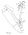
- a support element or portion 18 for a support post 17 for a seat 15 is mounted on and extends obliquely rearwardly upwardly from a rear wall of the transmission case 11, and the support post 17 is mounted for forward pivotal motion on the support portion 18.
- a bracket 19 is also mounted on and extends rearwardly from a lower portion of the transmission case 11, and a step plate 20 is mounted for pivotal motion on the bracket 19 such that it may be folded as indicated by chain lines when it is not to be used.
- the seat 16 which extends rearwardly from the frame 1 sometimes makes an obstruction to an operation depending upon operating conditions.
- the seat 16 and the step plate 20 are folded as indicated in phantom in Figs. 2 and 1, respectively, and the operator stands behind the car body and performs such operation as described above.
- the support post 17 is mounted for pivotal motion in forward and backward directions between an operative position and an inoperative position indicated by solid lines and in phantom in Fig. 2, respectively, around a horizontal axis provided by a pin 24 which is inserted in a hole 23 perforated at an upper end portion of the support portion 18 mounted on the rear wall of the transmission case 11.
- a lower end portion of the support post 17 abuts with and is held by a stopper 25 securely provided on a front side of the support portion 18 to limit rearward pivotal motion of the support post 17 to stop the seat 16 at a predetermined position.
- the support post 17 has a plurality of, three in the embodiment shown, pin fitting holes 26 perforated therein.
- the height or vertical location of the seat 16 can be adjusted by aligning an arbitrary one of the pin fitting holes 26 with the hole 23 of the support portion 15 and fitting the pin 24 into the thus aligned pin fitting hole 26 and hole 23. Since the support portion 15 and the stopper extend obliquely upwardly rearwardly when the height or vertical location of the seat 16 is adjusted, also the distance between the seat 16 and a bonnet 27 of the shovel car S is adjusted simultaneously so that a knee of a tall operator will not interfere with the bonnet 27.
- the seat 16 is mounted at an inner portion thereof for pivotal motion at an upper end of the support post 17.
- An L-shaped lever 28 is mounted for pivotal motion at another inner portion of the seat 16 and is normally urged in the counterclockwise direction in Fig. 2 by a spring 29.
- the lever 28 has a hook 28a formed provided at a free end portion thereof such that an arresting pin 30 mounted on a side face of the support post 17 is received in the hook 28a to secure the seat 16 at a predetermined angular position with respect to the support post 17.
- the other end portion 28b of the lever 28 is grasped by hand and pivoted in the clockwise direction in Fig. 2 to disengage the hook 28a of the lever 28 from the arresting pin 30, and then the seat 16 is pivoted in the clockwise direction in Fig. 2 to raise the front portion thereof upwardly.
- the support post 17 is pivoted forwardly to the inoperative position in which it extends vertically upwardly along the bonnet 27 as indicated in phantom in Fig. 2, and then the lever 28 is pivoted in the counterclockwise direction until the hook 28a thereof is engaged with a U-shaped bolt 31 mounted at an upper portion of the bonnet 27 to secure the seat 16 with respect to the bonnet 27.
- a U-shaped bolt 31 mounted at an upper portion of the bonnet 27 to secure the seat 16 with respect to the bonnet 27.
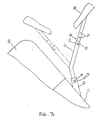
- a support portion 40 here has the form of a pipe. and a hole 41 is perforated in the support portion 40 and extends horizontally in a leftward and rightward direction while a pin fitting hole 43 corresponding to the hole 41 is perforated at a lower portion of a support post 42. A pin 44 is inserted in the hole 41 and pin fitting hole 43 to secure the support post 42 to the support portion 40.
- the support post 42 is bent rearwardly at an intermediate portion thereof, and a slide element 46 is fitted for axial sliding movement in a top portion of the support post 42.
- the support post 42 has a horizontal hole formed therein while the slide element 46 has a plurality of, three in the embodiment shown, holes 45 perforated therein, and an adjusting pin 47 is inserted in the hole of the support post 42 and one of the holes 45 of the slide element 46 registered with the hole of the support post 42 to secure the slide element 46 and hence a seat 48 securely mounted at the top end of the slide element 42 with respect to the support post 42.
- the height or vertical position of the seat 48 can be adjusted suitably by selecting a suitable one of the holes 45 of the slide element 46 which is to be registered with the hole of the support post 42 so as to allow the adjusting pint 47 is to be inserted in position.
- the pin 44 of the support post 40 is first pulled off the support portion 40 and then the support post 42 is pivoted by 180 degrees either in the clockwise or counterclockwise direction around an obliquely rearwardly inclined axis of the support post 42 provided by the support element 40 from an operative position indicated by solid lines to an inoperative position indicated in phantom in Fig. 3.
- the seat 48 is turned over in a forward and backward direction as indicated by chain lines and the pin fitting hole 43 of the support plate 42 is registered with the hole 41 of the support portion 40.
- the pin 44 is inserted into the thus registered hole 41 and pin hitting hole 43 thereby to secure the seat 48 with respect to the transmission case 11.
- the orientation of the support portion 40 and the bent angle of the support post 42 may be suitably determined from the overall length of the support post 42, the position of the seat 48 at which an operator is to be heated on the seat 48, the pivoted position of the support post 42 and so forth.
- a seat device for a very small size shovel car which does not extend, when it is not used, rearwardly from a car body of the shovel car to improve the handling facility and the operability of the shovel car.
- the seat device comprises a support element mounted at a rear lower portion of the car body and a support post mounted on the support element for pivotal motion around a horizontal axis or an obliquely rearwardly inclined axis between an operative position in which it is directed upwardly rearwardly and a seat face of a seat mounted at the top end thereof is directed upwardly to allow an operator to be seated thereon and an inoperative position in which the support post extends vertically upwardly along the car body and the seat face of the seat is directed rearwardly.
- the support post is secured at each of the operative and inoperative positions by suitable securing means.
Landscapes
- Engineering & Computer Science (AREA)
- Mining & Mineral Resources (AREA)
- Civil Engineering (AREA)
- General Engineering & Computer Science (AREA)
- Structural Engineering (AREA)
- Mechanical Engineering (AREA)
- Aviation & Aerospace Engineering (AREA)
- Transportation (AREA)
- Seats For Vehicles (AREA)
- Component Parts Of Construction Machinery (AREA)
Applications Claiming Priority (2)
| Application Number | Priority Date | Filing Date | Title |
|---|---|---|---|
| JP1180824A JPH0672444B2 (ja) | 1989-07-13 | 1989-07-13 | 超小型ショベルカーの座席装置 |
| JP180824/89 | 1989-07-13 |
Publications (3)
| Publication Number | Publication Date |
|---|---|
| EP0408008A2 true EP0408008A2 (de) | 1991-01-16 |
| EP0408008A3 EP0408008A3 (en) | 1992-01-08 |
| EP0408008B1 EP0408008B1 (de) | 1995-03-15 |
Family
ID=16089998
Family Applications (1)
| Application Number | Title | Priority Date | Filing Date |
|---|---|---|---|
| EP90113270A Expired - Lifetime EP0408008B1 (de) | 1989-07-13 | 1990-07-11 | Sitzvorrichtung für einen Löffelbagger |
Country Status (6)
| Country | Link |
|---|---|
| US (1) | US5065967A (de) |
| EP (1) | EP0408008B1 (de) |
| JP (1) | JPH0672444B2 (de) |
| KR (1) | KR930000285B1 (de) |
| DE (1) | DE69017777T2 (de) |
| ES (1) | ES2072337T3 (de) |
Cited By (2)
| Publication number | Priority date | Publication date | Assignee | Title |
|---|---|---|---|---|
| WO1996037379A1 (en) * | 1995-05-26 | 1996-11-28 | Applied Sweepers Limited | Seat assembly for pedestrian operated machine |
| EP0867331A3 (de) * | 1997-03-27 | 2000-01-19 | Applied Sweepers Limited | Sitzeinrichtung für dechselgesteuerte Kehrsaugmaschine |
Families Citing this family (8)
| Publication number | Priority date | Publication date | Assignee | Title |
|---|---|---|---|---|
| JPH0835153A (ja) * | 1994-07-22 | 1996-02-06 | Kanebo Ltd | 経編地用パイル糸およびその製造方法 |
| DE10127048B4 (de) * | 2000-06-07 | 2009-04-16 | Eloy Ayala Ruiz | Verbesserte Lastfördermaschine mit Aushubzusatz und zugehörigem Fahrgestell |
| US7047716B2 (en) * | 2003-02-28 | 2006-05-23 | Deere & Company | Convertible support |
| US9745719B1 (en) * | 2016-02-29 | 2017-08-29 | Deere & Company | Mechanical control arrangement for work vehicle |
| JP6577988B2 (ja) * | 2017-10-12 | 2019-09-18 | 本田技研工業株式会社 | 可動屋台 |
| DE102018202074A1 (de) * | 2018-02-09 | 2019-08-14 | Wirtgen Gmbh | Bodenbearbeitungsmaschine mit steckbarem Bediensitz |
| US12397691B2 (en) * | 2021-03-12 | 2025-08-26 | Mtd Products Inc | Outdoor power equipment with converter seated and standing operator positions |
| DE102021118210A1 (de) * | 2021-07-14 | 2023-01-19 | Liebherr-Werk Bischofshofen Gmbh | Arbeitsmaschine |
Family Cites Families (17)
| Publication number | Priority date | Publication date | Assignee | Title |
|---|---|---|---|---|
| US1268800A (en) * | 1917-11-21 | 1918-06-04 | Union City Body Company | Concealed seat for automobiles. |
| US1525743A (en) * | 1921-09-02 | 1925-02-10 | Gen Motors Corp | Seat support |
| US1593477A (en) * | 1923-09-15 | 1926-07-20 | Nat Convertible Body Company | Vehicle body |
| US2318751A (en) * | 1939-11-10 | 1943-05-11 | Carlson Philip | Vehicle seat |
| DE762889C (de) * | 1942-04-22 | 1954-11-02 | Paul Hempel | Einradschlepper, insbesondere fuer die Landwirtschaft |
| FR934307A (fr) * | 1946-09-23 | 1948-05-19 | Tracteur agricole avec outils | |
| US2565666A (en) * | 1948-12-16 | 1951-08-28 | White Motor Co | Shiftable vehicle seat |
| US2514249A (en) * | 1949-02-10 | 1950-07-04 | Alvin R Madsen | Planting and thinning vehicle |
| US2700411A (en) * | 1949-08-27 | 1955-01-25 | Chrysler Corp | Vehicle seat |
| US2740462A (en) * | 1950-02-23 | 1956-04-03 | Locke Steel Chain Co | Seat structure of a power lawn mower sulky |
| US2984311A (en) * | 1958-04-07 | 1961-05-16 | Inst Landmaschinen U Traktoren | Reversible driving mount for automotive vehicles |
| US3393009A (en) * | 1967-03-09 | 1968-07-16 | Leo H. Tart | Controlled swinging seat arrangement for row crop conveyor |
| US3642088A (en) * | 1970-02-02 | 1972-02-15 | Case Co J I | Self-locating vertically and facingly adjustable seat |
| US3841696A (en) * | 1972-12-20 | 1974-10-15 | Allis Chalmers | Adjustable tractor seat |
| JPS5151761U (de) * | 1974-10-15 | 1976-04-20 | ||
| CA1265338A (en) * | 1984-11-13 | 1990-02-06 | George C. Manning | Mechanical digger toy |
| JPH0428883Y2 (de) * | 1987-12-18 | 1992-07-14 |
-
1989
- 1989-07-13 JP JP1180824A patent/JPH0672444B2/ja not_active Expired - Lifetime
-
1990
- 1990-07-06 US US07/549,116 patent/US5065967A/en not_active Expired - Fee Related
- 1990-07-11 EP EP90113270A patent/EP0408008B1/de not_active Expired - Lifetime
- 1990-07-11 ES ES90113270T patent/ES2072337T3/es not_active Expired - Lifetime
- 1990-07-11 DE DE69017777T patent/DE69017777T2/de not_active Expired - Fee Related
- 1990-07-12 KR KR1019900010564A patent/KR930000285B1/ko not_active Expired - Fee Related
Cited By (3)
| Publication number | Priority date | Publication date | Assignee | Title |
|---|---|---|---|---|
| WO1996037379A1 (en) * | 1995-05-26 | 1996-11-28 | Applied Sweepers Limited | Seat assembly for pedestrian operated machine |
| GB2301071B (en) * | 1995-05-26 | 1998-08-19 | Applied Sweepers Ltd | Seat assembly for pedestrian operated machine |
| EP0867331A3 (de) * | 1997-03-27 | 2000-01-19 | Applied Sweepers Limited | Sitzeinrichtung für dechselgesteuerte Kehrsaugmaschine |
Also Published As
| Publication number | Publication date |
|---|---|
| EP0408008A3 (en) | 1992-01-08 |
| DE69017777T2 (de) | 1995-08-17 |
| US5065967A (en) | 1991-11-19 |
| EP0408008B1 (de) | 1995-03-15 |
| JPH0672444B2 (ja) | 1994-09-14 |
| KR910002640A (ko) | 1991-02-25 |
| DE69017777D1 (de) | 1995-04-20 |
| JPH0347328A (ja) | 1991-02-28 |
| ES2072337T3 (es) | 1995-07-16 |
| KR930000285B1 (ko) | 1993-01-15 |
Similar Documents
| Publication | Publication Date | Title |
|---|---|---|
| EP0408008B1 (de) | Sitzvorrichtung für einen Löffelbagger | |
| US5263810A (en) | Working implement connection structure for a working vehicle having a boom assembly | |
| US3984016A (en) | Attachment mounting for end loader | |
| US5540289A (en) | Stand apparatus for use in coupling and uncoupling a front loader | |
| US20130087398A1 (en) | Mounting Arrangement for Mounting Cooler Unit to Work Machine | |
| US10597851B2 (en) | Operation device for construction machine | |
| US8500386B2 (en) | Latching system for automatically securing front-mounted loader mast to tractor mounting frame | |
| WO2017075343A1 (en) | Ergonomic adjustment system for operator station | |
| US7674085B2 (en) | Arrangement and a method to attach a tool to a loader | |
| US5967737A (en) | Backhoe boom lock | |
| KR102475272B1 (ko) | 프론트 로더 퀵 조인트 및 이를 포함하는 프론트 로더 | |
| US3854752A (en) | Vehicle step mounting arrangement | |
| US4304305A (en) | Frame for mounting tilt and angled dozer blade to tractors | |
| CN103485376A (zh) | 工程机械 | |
| JP2010065439A (ja) | ローダ作業機の作業具装着装置 | |
| US4966518A (en) | Apparatus for controlling posture of front loader | |
| WO2023229775A1 (en) | Design for sensor and antenna field of view for semi-autonomous ctl | |
| US4109807A (en) | Support for loader lift arm | |
| US20080023206A1 (en) | Adjustable operator interface | |
| JPH05287772A (ja) | フロントローダ装着装置 | |
| JPH0344828Y2 (de) | ||
| JPS6124603Y2 (de) | ||
| WO2006036102A1 (en) | A method and a device to attach a tool to a loader | |
| JPH06146322A (ja) | フロントローダ装着型トラクタのフロントガード装置 | |
| JPH08282415A (ja) | 移動車輌の安全フレーム装置 |
Legal Events
| Date | Code | Title | Description |
|---|---|---|---|
| PUAI | Public reference made under article 153(3) epc to a published international application that has entered the european phase |
Free format text: ORIGINAL CODE: 0009012 |
|
| 17P | Request for examination filed |
Effective date: 19900711 |
|
| AK | Designated contracting states |
Kind code of ref document: A2 Designated state(s): DE ES FR GB IT NL |
|
| PUAL | Search report despatched |
Free format text: ORIGINAL CODE: 0009013 |
|
| AK | Designated contracting states |
Kind code of ref document: A3 Designated state(s): DE ES FR GB IT NL |
|
| 17Q | First examination report despatched |
Effective date: 19930210 |
|
| GRAA | (expected) grant |
Free format text: ORIGINAL CODE: 0009210 |
|
| AK | Designated contracting states |
Kind code of ref document: B1 Designated state(s): DE ES FR GB IT NL |
|
| ET | Fr: translation filed | ||
| REF | Corresponds to: |
Ref document number: 69017777 Country of ref document: DE Date of ref document: 19950420 |
|
| ITF | It: translation for a ep patent filed | ||
| REG | Reference to a national code |
Ref country code: ES Ref legal event code: FG2A Ref document number: 2072337 Country of ref document: ES Kind code of ref document: T3 |
|
| PLBE | No opposition filed within time limit |
Free format text: ORIGINAL CODE: 0009261 |
|
| STAA | Information on the status of an ep patent application or granted ep patent |
Free format text: STATUS: NO OPPOSITION FILED WITHIN TIME LIMIT |
|
| 26N | No opposition filed | ||
| PGFP | Annual fee paid to national office [announced via postgrant information from national office to epo] |
Ref country code: DE Payment date: 20010702 Year of fee payment: 12 |
|
| PGFP | Annual fee paid to national office [announced via postgrant information from national office to epo] |
Ref country code: GB Payment date: 20010711 Year of fee payment: 12 |
|
| PGFP | Annual fee paid to national office [announced via postgrant information from national office to epo] |
Ref country code: FR Payment date: 20010712 Year of fee payment: 12 |
|
| PGFP | Annual fee paid to national office [announced via postgrant information from national office to epo] |
Ref country code: NL Payment date: 20010723 Year of fee payment: 12 |
|
| PGFP | Annual fee paid to national office [announced via postgrant information from national office to epo] |
Ref country code: ES Payment date: 20010730 Year of fee payment: 12 |
|
| REG | Reference to a national code |
Ref country code: GB Ref legal event code: IF02 |
|
| PG25 | Lapsed in a contracting state [announced via postgrant information from national office to epo] |
Ref country code: GB Free format text: LAPSE BECAUSE OF NON-PAYMENT OF DUE FEES Effective date: 20020711 |
|
| PG25 | Lapsed in a contracting state [announced via postgrant information from national office to epo] |
Ref country code: ES Free format text: LAPSE BECAUSE OF NON-PAYMENT OF DUE FEES Effective date: 20020712 |
|
| PG25 | Lapsed in a contracting state [announced via postgrant information from national office to epo] |
Ref country code: NL Free format text: LAPSE BECAUSE OF NON-PAYMENT OF DUE FEES Effective date: 20030201 Ref country code: DE Free format text: LAPSE BECAUSE OF NON-PAYMENT OF DUE FEES Effective date: 20030201 |
|
| GBPC | Gb: european patent ceased through non-payment of renewal fee |
Effective date: 20020711 |
|
| PG25 | Lapsed in a contracting state [announced via postgrant information from national office to epo] |
Ref country code: FR Free format text: LAPSE BECAUSE OF NON-PAYMENT OF DUE FEES Effective date: 20030331 |
|
| NLV4 | Nl: lapsed or anulled due to non-payment of the annual fee |
Effective date: 20030201 |
|
| REG | Reference to a national code |
Ref country code: FR Ref legal event code: ST |
|
| REG | Reference to a national code |
Ref country code: ES Ref legal event code: FD2A Effective date: 20030811 |
|
| PG25 | Lapsed in a contracting state [announced via postgrant information from national office to epo] |
Ref country code: IT Free format text: LAPSE BECAUSE OF NON-PAYMENT OF DUE FEES Effective date: 20050711 |