EP0408103A1 - Electrode pour utilisations dans une cellule à combustible gazeux comportant un ensemble d'électrodes - Google Patents
Electrode pour utilisations dans une cellule à combustible gazeux comportant un ensemble d'électrodes Download PDFInfo
- Publication number
- EP0408103A1 EP0408103A1 EP90201721A EP90201721A EP0408103A1 EP 0408103 A1 EP0408103 A1 EP 0408103A1 EP 90201721 A EP90201721 A EP 90201721A EP 90201721 A EP90201721 A EP 90201721A EP 0408103 A1 EP0408103 A1 EP 0408103A1
- Authority
- EP
- European Patent Office
- Prior art keywords
- gas
- electrode
- reactant gas
- catalyst
- supporting plate
- Prior art date
- Legal status (The legal status is an assumption and is not a legal conclusion. Google has not performed a legal analysis and makes no representation as to the accuracy of the status listed.)
- Withdrawn
Links
Images

Classifications
-
- H—ELECTRICITY
- H01—ELECTRIC ELEMENTS
- H01M—PROCESSES OR MEANS, e.g. BATTERIES, FOR THE DIRECT CONVERSION OF CHEMICAL ENERGY INTO ELECTRICAL ENERGY
- H01M8/00—Fuel cells; Manufacture thereof
- H01M8/02—Details
- H01M8/0202—Collectors; Separators, e.g. bipolar separators; Interconnectors
- H01M8/0247—Collectors; Separators, e.g. bipolar separators; Interconnectors characterised by the form
- H01M8/0254—Collectors; Separators, e.g. bipolar separators; Interconnectors characterised by the form corrugated or undulated
-
- H—ELECTRICITY
- H01—ELECTRIC ELEMENTS
- H01M—PROCESSES OR MEANS, e.g. BATTERIES, FOR THE DIRECT CONVERSION OF CHEMICAL ENERGY INTO ELECTRICAL ENERGY
- H01M4/00—Electrodes
- H01M4/86—Inert electrodes with catalytic activity, e.g. for fuel cells
- H01M4/8605—Porous electrodes
- H01M4/8626—Porous electrodes characterised by the form
- H01M4/8631—Bipolar electrodes
-
- H—ELECTRICITY
- H01—ELECTRIC ELEMENTS
- H01M—PROCESSES OR MEANS, e.g. BATTERIES, FOR THE DIRECT CONVERSION OF CHEMICAL ENERGY INTO ELECTRICAL ENERGY
- H01M8/00—Fuel cells; Manufacture thereof
- H01M8/02—Details
- H01M8/0202—Collectors; Separators, e.g. bipolar separators; Interconnectors
- H01M8/0204—Non-porous and characterised by the material
- H01M8/0206—Metals or alloys
-
- H—ELECTRICITY
- H01—ELECTRIC ELEMENTS
- H01M—PROCESSES OR MEANS, e.g. BATTERIES, FOR THE DIRECT CONVERSION OF CHEMICAL ENERGY INTO ELECTRICAL ENERGY
- H01M8/00—Fuel cells; Manufacture thereof
- H01M8/02—Details
- H01M8/0202—Collectors; Separators, e.g. bipolar separators; Interconnectors
- H01M8/0204—Non-porous and characterised by the material
- H01M8/0206—Metals or alloys
- H01M8/0208—Alloys
-
- H—ELECTRICITY
- H01—ELECTRIC ELEMENTS
- H01M—PROCESSES OR MEANS, e.g. BATTERIES, FOR THE DIRECT CONVERSION OF CHEMICAL ENERGY INTO ELECTRICAL ENERGY
- H01M8/00—Fuel cells; Manufacture thereof
- H01M8/02—Details
- H01M8/0202—Collectors; Separators, e.g. bipolar separators; Interconnectors
- H01M8/0204—Non-porous and characterised by the material
- H01M8/0223—Composites
- H01M8/0228—Composites in the form of layered or coated products
-
- H—ELECTRICITY
- H01—ELECTRIC ELEMENTS
- H01M—PROCESSES OR MEANS, e.g. BATTERIES, FOR THE DIRECT CONVERSION OF CHEMICAL ENERGY INTO ELECTRICAL ENERGY
- H01M8/00—Fuel cells; Manufacture thereof
- H01M8/14—Fuel cells with fused electrolytes
- H01M2008/147—Fuel cells with molten carbonates
-
- H—ELECTRICITY
- H01—ELECTRIC ELEMENTS
- H01M—PROCESSES OR MEANS, e.g. BATTERIES, FOR THE DIRECT CONVERSION OF CHEMICAL ENERGY INTO ELECTRICAL ENERGY
- H01M2300/00—Electrolytes
- H01M2300/0017—Non-aqueous electrolytes
- H01M2300/0048—Molten electrolytes used at high temperature
- H01M2300/0051—Carbonates
-
- Y—GENERAL TAGGING OF NEW TECHNOLOGICAL DEVELOPMENTS; GENERAL TAGGING OF CROSS-SECTIONAL TECHNOLOGIES SPANNING OVER SEVERAL SECTIONS OF THE IPC; TECHNICAL SUBJECTS COVERED BY FORMER USPC CROSS-REFERENCE ART COLLECTIONS [XRACs] AND DIGESTS
- Y02—TECHNOLOGIES OR APPLICATIONS FOR MITIGATION OR ADAPTATION AGAINST CLIMATE CHANGE
- Y02E—REDUCTION OF GREENHOUSE GAS [GHG] EMISSIONS, RELATED TO ENERGY GENERATION, TRANSMISSION OR DISTRIBUTION
- Y02E60/00—Enabling technologies; Technologies with a potential or indirect contribution to GHG emissions mitigation
- Y02E60/30—Hydrogen technology
- Y02E60/50—Fuel cells
Definitions
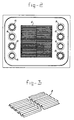
- the invention relates to an electrode for use in a gas fuel cell into which a reactant gas is passed in order to generate electrical energy, the electrode being provided with a virtually flat catalyst for ionizing the gas, a current collector which is arranged in direct contact with, and in electrical contact with, a flat surface of said catalyst in order to convey the current which is produced by the ionization of the reactant gas, said current collector being provided with a number of linear ribs which form alternatingly open and closed channels along the flat surface of the catalyst through which the reactant gas can be passed, and which electrode is provided with inlets and outlets for reactant gas and oxidizing gas, the supporting plate, provided with ribs, being composed of more than one part, the parts being offset with respect to one another so that the gas flow channels are not completely in line with one another, and also to a cell which is composed of a set of such electrodes.
- fuel cells are known for generating energy by electrochemical combustion of hydrogen.
- the advantage of this mode of combustion is the direct conversion into electricity, in addition to heat as a consequence of internal resistance in the (fuel) cell. As a result, process efficiencies of 60% and higher can be obtained.
- hydrogen is the fuel component in a fuel cell, it is also possible to use, inter alia, natural gas or coal gas as primary components.
- the molten-carbonate fuel cell is composed in principle of a plate-type anode, a matrix containing electrolyte and a cathode. This so-called active assembly of the fuel cell is enclosed on either side between one or more metal plates, termed current conductor and/or separator plate, which has to provide a number of functions such as: supporting the plate-type electrodes, passing the process gases over the electrodes, uniformly distributing the process gases over the electrode surface, conducting electrons between the separate fuel cells and separating the fuel gas and the oxidizing gas between anode and cathode of adjacent fuel cells.
- Figure 1 shows a basic diagram of a molten-carbonate fuel cell as described above, with the half-cell adjoining at both sides.
- 1 indicates the matrix
- 2 is a flat separating plate
- 3 is the gas container
- 4 is a corrugated plate
- 5 is the cathode
- 6 is again a matrix
- 7 is the anode
- 8 is again a corrugated plate
- 9 indicates the cathode
- a cell is then formed by the elements 5, 6 and 7 together with carbonate between the corrugated plates 4 and 12.
- the disadvantage of the generally standard electrode is that only half of the process gases are able to reach the electrode surface. In particular, this is a disadvantage for the use of the fuel because this part of the fuel leaves the cell unused.
- a device of the type described in the preamble has now been found which is characterized in that the sections of the supporting plate are offset with respect to one another by half a pitch length in the transverse direction.
- the ribs of the supporting plate are formed rectangularly and, in particular, it is preferable that the supporting and the corrugated plate are composed of more than two sections.
- the anode side of the supporting plate is manufactured from nickel or from nickel metal.
- the cathode side of the supporting plate is manufactured from stainless steel or from a high-quality nickel alloy.
- the fuel cell also has a uniform and consequently improved use of fuel. This improvement results, on the one hand, from a uniform temperature variation in the fuel cells and, on the other hand, from an improved use as a result of a higher effective cell voltage at the nominal current per unit area of the cell.
- nickel or a nickel-plated metal is preferably used.
- stainless steel or high-quality nickel steel is preferably used.
Landscapes
- Chemical & Material Sciences (AREA)
- Chemical Kinetics & Catalysis (AREA)
- Electrochemistry (AREA)
- General Chemical & Material Sciences (AREA)
- Life Sciences & Earth Sciences (AREA)
- Engineering & Computer Science (AREA)
- Manufacturing & Machinery (AREA)
- Sustainable Development (AREA)
- Sustainable Energy (AREA)
- Composite Materials (AREA)
- Fuel Cell (AREA)
- Inert Electrodes (AREA)
Applications Claiming Priority (2)
| Application Number | Priority Date | Filing Date | Title |
|---|---|---|---|
| NL8901798 | 1989-07-12 | ||
| NL8901798A NL8901798A (nl) | 1989-07-12 | 1989-07-12 | Electrode voor toepassing in de gasbrandstofcel, welke een verzameling electroden omvat. |
Publications (1)
| Publication Number | Publication Date |
|---|---|
| EP0408103A1 true EP0408103A1 (fr) | 1991-01-16 |
Family
ID=19855026
Family Applications (1)
| Application Number | Title | Priority Date | Filing Date |
|---|---|---|---|
| EP90201721A Withdrawn EP0408103A1 (fr) | 1989-07-12 | 1990-06-28 | Electrode pour utilisations dans une cellule à combustible gazeux comportant un ensemble d'électrodes |
Country Status (4)
| Country | Link |
|---|---|
| EP (1) | EP0408103A1 (fr) |
| JP (1) | JPH0355763A (fr) |
| CA (1) | CA2021041A1 (fr) |
| NL (1) | NL8901798A (fr) |
Cited By (1)
| Publication number | Priority date | Publication date | Assignee | Title |
|---|---|---|---|---|
| EP0616380A1 (fr) * | 1993-03-16 | 1994-09-21 | FINMECCANICA S.p.A. AZIENDA ANSALDO | Distribiteur de gaz pour piles à combustible à carbonates fondus |
Families Citing this family (3)
| Publication number | Priority date | Publication date | Assignee | Title |
|---|---|---|---|---|
| JP4769467B2 (ja) * | 2005-02-07 | 2011-09-07 | 株式会社TanaーX | 商品陳列ハンガー |
| JP2009277390A (ja) * | 2008-05-12 | 2009-11-26 | Central Res Inst Of Electric Power Ind | 燃料電池の流路板及びこれを用いた燃料電池 |
| CN113871790A (zh) * | 2020-06-30 | 2021-12-31 | 比亚迪股份有限公司 | 一种锂离子电池极片及锂离子电池 |
Citations (4)
| Publication number | Priority date | Publication date | Assignee | Title |
|---|---|---|---|---|
| US4548876A (en) * | 1984-10-17 | 1985-10-22 | The United States Of America As Represented By The United States Department Of Energy | Integrated current collector and catalyst support |
| JPS6386361A (ja) * | 1986-09-30 | 1988-04-16 | Hitachi Ltd | 積層形燃料電池用セパレータ |
| JPH01115066A (ja) * | 1987-10-28 | 1989-05-08 | Hitachi Ltd | 溶融炭酸塩型燃料電池 |
| JPH01140560A (ja) * | 1987-11-27 | 1989-06-01 | Hitachi Ltd | 溶融炭酸塩型燃料電池 |
-
1989
- 1989-07-12 NL NL8901798A patent/NL8901798A/nl not_active Application Discontinuation
-
1990
- 1990-06-28 EP EP90201721A patent/EP0408103A1/fr not_active Withdrawn
- 1990-07-12 JP JP2187004A patent/JPH0355763A/ja active Pending
- 1990-07-12 CA CA002021041A patent/CA2021041A1/fr not_active Abandoned
Patent Citations (4)
| Publication number | Priority date | Publication date | Assignee | Title |
|---|---|---|---|---|
| US4548876A (en) * | 1984-10-17 | 1985-10-22 | The United States Of America As Represented By The United States Department Of Energy | Integrated current collector and catalyst support |
| JPS6386361A (ja) * | 1986-09-30 | 1988-04-16 | Hitachi Ltd | 積層形燃料電池用セパレータ |
| JPH01115066A (ja) * | 1987-10-28 | 1989-05-08 | Hitachi Ltd | 溶融炭酸塩型燃料電池 |
| JPH01140560A (ja) * | 1987-11-27 | 1989-06-01 | Hitachi Ltd | 溶融炭酸塩型燃料電池 |
Non-Patent Citations (6)
| Title |
|---|
| EXTENDED ABSTRACTS, vol. 87-1, 1987, pages 65-66, Spring (Meeting), Philadelphia, Pennsylvania, US; H.S. HAU et al.: "Corrosion of Fe-25Cr-20Ni alloy in molten alkali carbonates" * |
| PATENT ABSTRACTS OF JAPAN, vol. 10, no. 175 (E-413)[2231], 20th June 1986; & JP-A-61 24 158 (MITSUBISHI DENKI K.K.) 01-02-1986 * |
| PATENT ABSTRACTS OF JAPAN, vol. 10, no. 317 (E-449)[2373], 28th October 1986; & JP-A-61 128 469 (HITACHI LTD) 16-06-1986 * |
| PATENT ABSTRACTS OF JAPAN, vol. 11, no. 187 (E-516)[2634], 16th June 1987; & JP-A-62 17 959 (FUJI ELECTRIC CO.) 26-01-1987 * |
| PATENT ABSTRACTS OF JAPAN, vol. 13, no. 173 (E-748)[3521], 24th April 1989; & JP-A-1 3960 (HITACHI LTD) 09-01-1989 * |
| PATENT ABSTRACTS OF JAPAN, vol. 13, no. 173 (E-748)[3521], 24th April 1989; & JP-A-1 3962 (HITACHI LTD) 09-01-1989 * |
Cited By (1)
| Publication number | Priority date | Publication date | Assignee | Title |
|---|---|---|---|---|
| EP0616380A1 (fr) * | 1993-03-16 | 1994-09-21 | FINMECCANICA S.p.A. AZIENDA ANSALDO | Distribiteur de gaz pour piles à combustible à carbonates fondus |
Also Published As
| Publication number | Publication date |
|---|---|
| CA2021041A1 (fr) | 1991-01-13 |
| NL8901798A (nl) | 1991-02-01 |
| JPH0355763A (ja) | 1991-03-11 |
Similar Documents
| Publication | Publication Date | Title |
|---|---|---|
| EP0408104B1 (fr) | Plaque séparatrice pour utilisation dans une cellule à combustible gazeux comportant un ensemble d'électrodes, ainsi qu'une pile de cellules à combustible | |
| US5348814A (en) | Internal reforming type molten carbonate fuel cell | |
| EP0451971B1 (fr) | Cellules à combustible à oxide solide | |
| US6811913B2 (en) | Multipurpose reversible electrochemical system | |
| JP2711018B2 (ja) | 燃料電池 | |
| EP0861506B1 (fr) | Convertisseur electrochimique a haute temperature pour carburants hydrocarbones | |
| US5338621A (en) | Apparatus for converting chemical energy of fuel into electrical energy with a plurality of high-temperature fuel cells | |
| AU688484B2 (en) | Electrochemical converter having optimal pressure distribution | |
| US7163759B2 (en) | Solid oxide fuel cell stack assembly having tapered diffusion layers | |
| JPH03105865A (ja) | 内部改質型燃料電池およびそれを用いた発電プラント | |
| JP3317535B2 (ja) | 燃料電池 | |
| JP2005183084A (ja) | 燃料電池 | |
| JPH06196184A (ja) | 燃料電池用触媒充填器 | |
| EP0408103A1 (fr) | Electrode pour utilisations dans une cellule à combustible gazeux comportant un ensemble d'électrodes | |
| KR100418626B1 (ko) | 용융탄산염형 연료전지 | |
| US20070269697A1 (en) | Solid Electrolyte Fuel Cell | |
| US7972742B2 (en) | Tube type fuel cell to decrease current path length | |
| US7803493B2 (en) | Fuel cell system with separating structure bonded to electrolyte | |
| US20050008925A1 (en) | Fuel cell | |
| JPS63158754A (ja) | 内部改質形燃料電池 | |
| JPH06314570A (ja) | 燃料電池のマニホールド構造 | |
| JP2001202974A (ja) | 固体高分子型燃料電池スタック | |
| KR0127187Y1 (ko) | 용융탄산염 연료전지 | |
| KR20040003349A (ko) | 연료전지의 압력손실 방지구조 | |
| JP2007188849A (ja) | 燃料電池セル及びスタックの構造 |
Legal Events
| Date | Code | Title | Description |
|---|---|---|---|
| PUAI | Public reference made under article 153(3) epc to a published international application that has entered the european phase |
Free format text: ORIGINAL CODE: 0009012 |
|
| AK | Designated contracting states |
Kind code of ref document: A1 Designated state(s): AT BE CH DE DK ES FR GB GR IT LI LU NL SE |
|
| 17P | Request for examination filed |
Effective date: 19901121 |
|
| 17Q | First examination report despatched |
Effective date: 19920803 |
|
| STAA | Information on the status of an ep patent application or granted ep patent |
Free format text: STATUS: THE APPLICATION IS DEEMED TO BE WITHDRAWN |
|
| 18D | Application deemed to be withdrawn |
Effective date: 19930216 |