EP0408122B1 - Circuit pour une imprimante matricielle - Google Patents
Circuit pour une imprimante matricielle Download PDFInfo
- Publication number
- EP0408122B1 EP0408122B1 EP90201800A EP90201800A EP0408122B1 EP 0408122 B1 EP0408122 B1 EP 0408122B1 EP 90201800 A EP90201800 A EP 90201800A EP 90201800 A EP90201800 A EP 90201800A EP 0408122 B1 EP0408122 B1 EP 0408122B1
- Authority
- EP
- European Patent Office
- Prior art keywords
- signal
- printing
- counter
- pulses
- Prior art date
- Legal status (The legal status is an assumption and is not a legal conclusion. Google has not performed a legal analysis and makes no representation as to the accuracy of the status listed.)
- Expired - Lifetime
Links
Images


Classifications
-
- B—PERFORMING OPERATIONS; TRANSPORTING
- B41—PRINTING; LINING MACHINES; TYPEWRITERS; STAMPS
- B41J—TYPEWRITERS; SELECTIVE PRINTING MECHANISMS, i.e. MECHANISMS PRINTING OTHERWISE THAN FROM A FORME; CORRECTION OF TYPOGRAPHICAL ERRORS
- B41J2/00—Typewriters or selective printing mechanisms characterised by the printing or marking process for which they are designed
- B41J2/22—Typewriters or selective printing mechanisms characterised by the printing or marking process for which they are designed characterised by selective application of impact or pressure on a printing material or impression-transfer material
- B41J2/23—Typewriters or selective printing mechanisms characterised by the printing or marking process for which they are designed characterised by selective application of impact or pressure on a printing material or impression-transfer material using print wires
- B41J2/30—Control circuits for actuators
Definitions
- the invention relates to a circuit arrangement for controlling the mechanical printing elements of a matrix printer, which are arranged in a printing head moved along the printing line and which generate characters to be printed by printing dots which are arranged in at least one predetermined printing pattern, with a control arrangement for each printing element individually providing a printing signal generated when this printing element reaches a position which lies on a recording medium by a certain printing path in front of a designated printing point.
- Matrix printers with a number of print elements arranged in a print head are generally known in a wide variety of designs, for example from DE-PS 26 32 293.
- the mechanical print element In order to print at precisely defined locations on a recording medium, in particular when printing in both directions of movement of the print head, the mechanical print element must can already be activated before this point on the record carrier is reached, in particular by the pressure delay time between the activation of the printing element, ie the pressure needle driven by an electromagnet, and to compensate for their impact on the recording medium.
- the printhead has moved a certain distance, which depends not only on the needle flight time but also on the printhead speed.
- the compensation of the needle flight time can be done by a fixed time reserve.
- DE-A-37 27 049 Another problem is dealt with by DE-A-37 27 049. It describes a print head control system for a construction in which a large number of print needles are arranged in a compact manner, which should result in problems with pinpoint accuracy due to the overlapping control currents.
- two storage devices are used, the first of which is the number of Stores print needles shot by the driven solenoid circuits from the previous drive timing while the second storage means is used to store the number of print needles to be shot by solenoid circuits driven by the subsequent drive timing.
- a computing device for calculating the times correcting the time-of-flight control and a time control device are used.
- DE - B - 25 52 667 deals with a fast printer with different printing speeds.
- the method for operating this high-speed printer uses a control system with which a variable signal is generated, which is fed to the printer in each case during a printing cycle in which a print character is reproduced after an interval of the stop of the write head.
- the print head When starting at the beginning of a print line and at the end of a print line (each seen in the current direction of movement of the print head), the print head still does not or no longer has its intended speed, so that the print head requires a start-up distance and an exit distance during which it does not print. As a result, the dimensions of the entire matrix printer and thus also the production costs are increased and the printing output is reduced.
- the object of the invention is to provide a circuit arrangement of the type mentioned at the outset which, even at different speeds of the print head, in particular when starting and stopping at the beginning or end of a printing line, enables printing at defined locations on the recording medium.
- the speed-dependent delay practically results in a path-dependent or location-dependent shift of the actual drive signal for the printing element, so that the point of impact of the printing element on the recording medium is practically always the same regardless of the printhead speed.
- the print head speed can be derived via position pulses from the scanning of the successive positions of the print head, for example by scanning a fixed linear grid by the print head.
- a simple implementation of the delay arrangement according to one embodiment of the invention is that the delay arrangement is a counter and the print signal sets the counter to a correction value which is dependent on the printhead speed, and the counter then counts to a final value by means of a count pulse input and reaches this when it is reached The control signal starts.
- the correction value can be clearly determined from the print head speed and the frequency of the counting pulses in connection with the final value of the counter.
- the delay arrangement is a shift register and the print signal writes a first binary value into a stage of the shift register determined by a correction value which is dependent on the printhead speed, and the content of the shift register is then shifted on by means of shift pulses is and the arrival of the first binary value in a predetermined level of the shift register starts the control signal.
- the delay arrangement is a shift register and the print signal writes a first binary value into a stage of the shift register determined by a correction value which is dependent on the printhead speed, and the content of the shift register is then shifted on by means of shift pulses is and the arrival of the first binary value in a predetermined level of the shift register starts the control signal.
- the delay arrangement is a shift register and the print signal writes a first binary value into a stage of the shift register determined by a correction value which is dependent on the printhead speed, and the content of the shift register is then shifted on by means of shift pulses is and the arrival of the first binary value in a predetermined level of the shift register starts the control signal.
- the counting pulses or shift pulses are derived from position pulses which are generated when the print head moves.
- the counter or the shift register therefore performs a path-dependent counting or shifting, as a result of which a path is practically measured.
- a correction arrangement for generating the correction value, which has a first counter with parallel set inputs, a clock signal of constant frequency at its count input and one at its set inputs corresponding to the print delay time between the activation of the print element and its impact on the recording medium Receives value with reference to the clock signal, and contains a second counter with parallel setting inputs, which receives the position pulses at its counting input and a value corresponding to the specific printing path at maximum speed of the printing element at its counting inputs, so that both counters receive the same setting control signal obtained, and that a carry signal of the first counter outputs a value derived from the position of the second counter then reached as a correction value to the delay arrangement.
- the basic idea is used that the parallel activation of two counters, one of which counts a time, namely the pressure delay time or the needle flight time of a printing needle, and the other counter counts position-dependent position pulses, converts a time into a path, and in the way that the print head needs at the current speed to get from the activation point of the printing element to the printing point on the recording medium.
- the print signal since the print signal is already generated at a point on the print head that is further away from the desired print point, namely by the specific print path at maximum print head speed, the print signal must be delayed by a distance of the print head that corresponds to the remaining content of the second counter corresponds. This indicates the correction value.
- this correction value changes when the speed of the print head changes, so that new, updated correction values have to be determined continuously, particularly during the start-up and run-down of the print head.
- an embodiment of the invention is characterized in that the set control signal is derived with a delay from the carry signal. In this way, a new correction value is determined at almost maximum speed, and the delay of the setting control signal can be selected depending on the processing speed in the logic circuit used.
- a further embodiment of the invention is characterized in that the occurrence of a carry signal of the second counter occurs before the carry signal of the first counter occurs Error signal generated. It is expedient that the error signal is derived at least one clock period from the occurrence condition of the two carry signals and that the error signal is suppressed if a carry signal of the first counter occurs within the delay time of the error message. In this case, it can be assumed that the limit condition has just been reached, but that there is no real error, so that the correct correction value 0 has then been generated.
- a simple control of the counter is possible according to one embodiment of the invention in that a switch is connected upstream of the counter clock input of the counter, which successively supplies the counter clock input with a rest signal or counting pulses with one of the three frequencies, that the counter generates a carry signal at the end position and with the next counting cycle starts counting again from the initial position and that the carry signal switches on a further counting arrangement with four positions, which controls the changeover switch and, with an incoming pressure signal, a loading signal for the first counter generated and goes into the first working position and generates the output signal during the second working position.
- the further counting arrangement is simple, since it only has to have four positions.
- the output of the shift register can be followed by a counter which is driven in a corresponding manner as described above with the second and third frequencies or with the idle signal.
- a counter is required for each individual printing element, so that a shift register output controls several counters simultaneously depending on the data to be printed .
- Fig. 1 is in front of a record carrier, which is only indicated here as print line L, a print element D, which is moved in the direction of the arrow shown along the print line L.
- This printing element D is intended to print a point on the printing line at position P1.
- the printing element D consists in particular of a magnet which mechanically activates a printing needle when electrically actuated, ie strikes the printing line L. Since the end of the print needle is at a certain distance from the print line L of the record carrier before the control, a certain time elapses after the control of the print element until the needle hits the record carrier.
- the electrical control of the printing element D In order to print the point P1, the electrical control of the printing element D must take place before it has reached this pressure point P1, depending on the speed of movement of the printing element D.
- the maximum speed assume that the printing element D must already be controlled electrically when it has reached the point P2 on the printing line L. This applies at a constant speed for all printing dots, so that the control pattern of the printing element D is quasi shifted by a certain printing path compared to the printing pattern on the recording medium.
- a corresponding shift to the other side is then necessary. This shift can easily be taken into account when generating the pressure signals, at least for a constant speed of the pressure element.
- a speed of the printing element is expediently assumed, which is at least the same, but for reasons of safety it is greater than the maximum speed of the printing element.
- the electrical actuation of the printing element D for the same printing point P1 must take place at a different location on the printing line L. If the printing element D is still activated at point P2, it has only reached point P4 at a lower speed in the direction of the arrow after the needle flight time of the printing needle when the printing needle hits the recording medium. The actuation and thus the mechanical activation of the printing element D must therefore be delayed by the distance between the points P1 and P4 compared to the pressure signal generated in advance by the constant displacement at Ps, namely at the point P3 in order to print again at the point P1. So the pressure signal must be delayed by the distance between P2 and P3.
- FIG. 2 schematically shows an arrangement for controlling an electromechanical printing element of a matrix printer, in which a speed-dependent delay is carried out between the printing signal and the driving signal of the printing element.
- position pulses are supplied, which are derived from the movement of the printing element D, the distance between two position pulses thus a certain distance of the Pressure element D corresponds.
- These position pulses are fed to an arrangement 48, which preferably accumulates the position pulses, so that a value indicating the position of the printing element is produced at the output 49.
- This is fed to a comparator 58, which receives a desired position of the pressure element via a further input 59. This can be point P2 in FIG. 1, for example.
- the comparator 58 emits a pressure signal at the output 24. It is assumed that only positions that are actually to be printed are fed to the input 59. However, it is also possible to use the input 59 to feed positions of a printing raster on which a printing dot is possible, but depending on the information to be printed out, which is stored, for example, pixel by pixel in a memory, the printing signal 24 then being fed to this memory.
- a delay arrangement 6 is supplied with a pressure signal via line 24. After a delay time which is determined by a correction value supplied via the connection 14 by a correction arrangement 8, this delay arrangement 6 emits on the line 21 a control signal to the printing magnet 7, which sets the printing needle in direct motion.
- a matrix printer generally contains a larger number of printing elements in one print head. If the positions of a print screen are supplied via the input 59, the arrangements 48 and 58 as well as the correction arrangement 8 for generating the correction value on the connection 14 can be common for all print elements of the print head.
- the correction value on the connection 14 is generated by the correction arrangement 8 from the position pulses on the line 26 and from a clock signal of constant frequency on a line 9 and from further, fixed parameters.
- the circuit arrangement shown in FIG. 3 represents an embodiment of the delay arrangement 6, which is actually present in many cases, namely here once for each printing element. It contains a counter 10, and each counter serves both to delay the print signal depending on the printhead speed and to determine the activation time or activation time of the printing element or the printing elements and to determine the subsequent one Break time.
- the counter can be set to the correction value K by a signal DS ', which is supplied by the correction arrangement 8 via the multiple connection 14.
- This signal DS ' is generated from the pressure signal DS coming from the outside via line 24 in the AND gate 22 when this is released by the signals on lines 17 and 19 of D flip-flops 16 and 18 in their rest position.
- the counter 10 receives counting clocks f1, f2 and f3 from a switchover arrangement 12, which can expediently be designed as a 4: 1 multiplexer and which is controlled via the lines 13 and 15 by the working outputs of the D flip-flops 16 and 18. In its idle state, input 1, which receives an idle signal, is switched through to the counting input of counter 10, so that counter 10 does not count.
- a switchover arrangement 12 which can expediently be designed as a 4: 1 multiplexer and which is controlled via the lines 13 and 15 by the working outputs of the D flip-flops 16 and 18.
- input 1 which receives an idle signal, is switched through to the counting input of counter 10, so that counter 10 does not count.
- the AND gate 20 generates an enable signal for the control of the magnets of the corresponding printing elements at the output 21, and in addition the switching arrangement 12 now carries the clock signal supplied via the input 3 to the counter 10 to.
- This clock signal has such a fixed frequency f2 that the counter 10 during the time that the magnets must remain energized, after the generation of the carry signal reaches the end position starting from the start position, at which a carry signal is again generated on line 11. It should be noted that instead the counter also depends on the end position can count down to the starting position if this is technically more favorable.
- the counter After the time period t a , which corresponds to the actuation time of the printing magnets, the counter reaches the end position E a second time, namely at time t2, and a carry signal appears on line 11 in FIG. 3, which the D flip-flop 16 in the idle position switches because there is a logical "0" on line 19 because of the working position of the D-flip-flop 18.
- the D flip-flop 18 remains in the working position.
- the signal generated by the AND gate 20 at the output 21 thus ends, while the changeover switch 12 is also switched on, so that the counter 10 receives the clock signal fed to the input 4 at the frequency f3.
- This frequency determines the pause time t p until time t3, which is dimensioned such that the sum of all three sections t k , t a and t p is greater than the period t r of the actuation of the pressure elements.
- the D flip-flops 16 and 18 represent a counter with four positions, which, however, can also be implemented in any other way.
- the arrangement described is required at least for each group of printing needles that coincide with the printing screen. However, it is also possible to provide such an arrangement for each pressure element, the pressure signal supplied via line 24 being directly assigned to a specific pressure element whose pressure magnet is controlled individually via line 21.
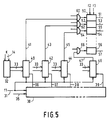
- FIG. 5 Another circuit arrangement in which the delay of the pressure signals is carried out by shift registers is shown in FIG. 5.
- a delay arrangement 30 which generates time-dependent pressure signals at the outputs 36 to 39 from the arrangement of the printing elements in the print head, as described in the earlier, not previously published application P 39 07 080.8.
- These delayed print signals are derived from a signal supplied via line 35, which depends on the density of the print screen and which is pushed through the arrangement 30 by a clock signal on line 31, the frequency f1 of this clock signal being derived from the position pulses of the print head .
- the correction value K is generated in a corresponding manner as indicated in FIG. 1 and coded via the multiple line 14 to a decoder 32 which converts this correction value K into a 1-out-of-n representation on the multiple line 33.
- This multiple line 33 leads to the parallel set inputs of a number of shift registers 40, 42, 44 to 46, the load input with one each of the outputs 36 to 39 of the arrangement 30 is connected and, in the case of a signal on an output, writes the current decoded correction value into the shift register in question.
- This means that a certain level in the shift register is set to a first binary value, for example logically "1", while at least a number of levels in front of it contain the other binary value.
- This logic value "1" is then shifted with the clock signal with the frequency f1 on line 31 until it arrives at the end of the shift register.
- the outputs 41, 43, 45 to 47 of the shift registers 40, 42, 44 to 46 each lead to an AND gate 60, 62, 64 to 66, which receives delayed signals from a character generator at the other, unspecified input.
- the outputs of the AND gates control counting arrangements 50, 52, 54 to 56, which can be constructed similarly to the circuit shown in FIG. 3, but here are only alternately either in the idle state or are counted on with clock signals with the frequencies f2 or f3 .
- the outputs 51, 53, 55 to 57 of the counting arrangements then control the electromagnets of printing needles.
- the counting arrangements 50, 52, 54 to 56 are used to determine the duration of the actuation of the electromagnets and the subsequent pause times, while the shift registers 40, 42, 44 to 46 generate the delay dependent on the print head speed of the delays at the outputs 36 to 39 of the arrangement 30 Cause pressure signals.
- the instantaneous print head speed is contained both in the correction value K supplied via the connection 14 and in the frequency f1 of the clock signal on the line 31.
- the structure of the correction arrangement 8 (FIG. 2) for generating the correction value K is shown in more detail in FIG. 6.
- This contains two registers 70 and 80, each for a data word with a number of bits, to each of which a data word is fed in parallel via an input 25, which in register 70 with a write signal on line 27 and in register 80 with a write signal on Line 29 is registered.
- the output of the register 70 leads to the parallel set inputs 71 of a counter 72, which receives clock signals of constant frequency via the line 9 at its counter input.
- a value has been written into the register 70 which corresponds to the needle flight time of the printing needle of a printing element, based on the clock signals on the Line 9, ie if the counter 72 is set to this value by a setting control signal on line 75, it just reaches its end position during the entire needle flight time and generates a carry signal at output 73.
- the output of register 80 is with set inputs 81 connected to a counter 82, which receives the position pulses supplied via line 26 at its counter input.
- the value written into the register 80 corresponds to the path of the printing element during the needle flight time at the maximum speed of the printing element, ie, based on FIG. 1, the number of position pulses during the movement of the printing element D from point P2 to pressure point P1. If, with the set control signal on line 75, both counters 72 and 82 are simultaneously set to their respective positions, at maximum speed of the printing element, ie at the highest frequency of the position pulses on line 26, counter 82 just reaches its end position when counter 72 reaches its end position and emits a carry signal on line 73.
- the carry signal on line 73 also drives a delay 74 which generates the set control signal on line 75.
- the delay element 74 serves, in particular, to ensure the correct transfer of the counter reading of the counter 82 into the register 84 before the counter 82 is set again on the line 75 by the setting control signal.
- the write signal on line 27 also drives delay element 74 in order to start the determination of the correction value. When using corresponding components or circuit technology, the delay element 74 can also be omitted.
- a carry signal on line 83 cannot appear earlier than counter 72 has generated a carry signal on line 73.
- an AND gate 76 is provided which emits a signal on the output line 77 if the carry signal appears on the line 83 while no carry signal has yet occurred on the line 73.
- the output 77 is connected to the D input of a D flip-flop 78 which, with the next clock signal on line 9, accepts the signal on line 77 and outputs it at output 79. This can already be evaluated as an error signal.
- the flip-flop 78 is still set, but the signal at the output 77 of the AND gate 76 then disappears that the flip-flop 88 then no longer is set. The correct zero correction value then arises at output 14.
- registers 70 and 80 By using registers 70 and 80, the default values for counters 72 and 82 can be easily changed. If, for example, the maximum print head speed is reduced, for example for printing in a particularly narrow print pattern for high print quality, the value in register 80 can be reduced accordingly, but then the distance or the shift of the print signals with respect to the dots to be printed is also smaller must be chosen.
- the value written in register 70 is reduced if a thicker set of forms is to be printed instead of a sheet, since then the needle flight time is shorter. Decreasing is understood to mean that the counters 72 and 82 then require a smaller number of pulses at the counter input in order to reach the end position, for which the counters at the set inputs 71 and 81, for example, have the complement values of those written into the registers 70 and 80 Get values.
- the delay of the print signals can also be achieved by other technical possibilities. For example, by using analog controllable delay elements.
Landscapes
- Character Spaces And Line Spaces In Printers (AREA)
Claims (8)
- Dispositif de commande pour la commande des éléments mécaniques d'impression d'une imprimante à matrice, ces éléments étant arrangés dans une tête d'impression (D), qui suit une ligne d'impression (L), et produisant les caractères à imprimer à l'aide de points d'impression, disposés dans une trame d'impression donnée, tandis qu'une unité de commande génère un signal d'impression individuel pour chacun des éléments d'impression, dès que l'éléments d'impression respectif atteint une position, situé à une certaine distance avant la position d'impression prévue (P) sur un support d'imformation, caractérisé en ce que les éléments d impression (7) dans la tête d'impression (D) sont reliés à un dispositif retardateur (6), qui, en cas de commande par un signal d'impression (24) après un retard, déterminé par la vitesse de la tête d'impression, déclenche un signal de commande (21) pour l'activation mécanique immédiate de l'élément d'impression (7) respectif.
- Dispositif selon la revendication 1., caractérisé en ce que le dispositif retardateur (6) consiste en un compteur (10) et que le signal d'impression (DS) met le compteur (10) à une valeur de correction, qui dépend de la vitesse de la tête d'impression, et que le compteur (10) compte alors jusqu'à une valeur finale à l'aide d'impulsions de comptage, reçues par son entrée d'impulsion de comptage, et déclenche ensuite le signal de commande, dès que cette valeur finale est atteinte.
- Dispositif de commande selon la revendication 1., caractérisé en ce que le dispositif retardateur (6) consiste en un registre de décalage (40, 42, 44 à 46) et que le signal d'impression (DS) inscrit une première valeur binaire à un certain niveau du registre de décalage, ce niveau étant déterminé par une valeur de correction, qui dépend de la vitesse de la tête d'impression, et que le contenu du registre de décalage (40, 42, 44 à 46) est ensuite déplacé à l'aide d'impulsions de décalage et que l'arrivée de la première valeur binaire à un niveau donné du registre de décalage déclenche le signal de commande (21).
- Dispositif de commande selon les revendications 2. ou 3., caractérisé en ce que les impulsions de comptage ou de décalage sont dérivées d'impulsions de position (26), générées lors de mouvement de la tête d'impression (D).
- Dispositif de commande selon la revendication 1., caractérisé en ce qu'il existe un dispositif de correction (8) pour la génération de la valeur de correction (14), ce dispositif comprenant un premier compteur (72) avec des entrées de positionnement parallèles (71), qui reçoit, à son entrée de comptage, une impulsion de synchronisation (9) à fréquence constante et, à ses entrées de positionnement (71), une valeur, qui correspond au retard entre l'activation de l'élément d'impression (7) et son impact sur le support d'information et qui a un rapport avec le signal de synchronisation, ainsi qu'un deuxième compteur (82) avec des entrées de positionnement parallèles (81), qui reçoit, à son entrée de comptage, les impulsions de position (26) et, à ses entrées de positionnnement (81) une valeur, qui correspond à une certaine voie d'impression à vitesse maximale de l'élément d'impression (7); que les deux compteurs (72, 82) reçoivent le même signal de commande de positionnement (75) et qu'un signal de transfer (73) du premier compteur (72) transmet une valeur de correction (14) au dispositif retardateur (6), cette valeur de correction étant dérivée de la position, atteinte alors par le deuxiéme compteur (82).
- Dispositif de commande selon revendication 5., caractérisé en ce que l'apparition d'un signal de transfert (83) du deuxième compteur (82) avant l'apparition du signal de transfert (73) du premier compteur (72) génère un signal d'erreur (89).
- Dispositif de commande selon revendication 6., caractérisé en ce que le signal d'erreur (89) est dérivé des conditions d'apparition des deux signaux de transfert (73, 83) avec un retard d'au moins une période de synchronisation, et que le signal d'erreur (89) est supprimé, s'il y a, durant la période de retard du message d'érreur, un signal de transfert (73) du premier compteur (72).
- Dispositif de commande selon revendication 2., caractérisé en ce que le compteur (10), après avour atteint la première valeur final (E), commute l'entrée des impulsions de comptage aux impulsions de comptage d'une deuxième fréquence constante (f2), qui correspond au temps d'activation d'un élément d'impression (D) et qui, dès que la position finale (E) est atteinte de nouveau, met fin au promier signal de commande et commute l'entrée des impulsions de comptage aux impulsions de comptage d'une troisième fréquence (f3), qui est choisie de manière à ce que, à vitesse maximale de la tête d'impression, le compteur (10) atteigne la position finale (E) pour la troisième fois, après qu'au moins une durée de période donnée de l'élément d'impression (tr) se soit écoulée depuis le signal d'impression (DS), d'autres signaux d'impression (DS) étant bloqués jusqu'à ce moment.
Applications Claiming Priority (4)
| Application Number | Priority Date | Filing Date | Title |
|---|---|---|---|
| DE3922616 | 1989-07-10 | ||
| DE19893922616 DE3922616A1 (de) | 1989-07-10 | 1989-07-10 | Schaltungsanordnung fuer einen matrixdrucker |
| DE19904007537 DE4007537A1 (de) | 1990-03-09 | 1990-03-09 | Schaltungsanordnung fuer einen matrixdrucker |
| DE4007537 | 1990-03-09 |
Publications (3)
| Publication Number | Publication Date |
|---|---|
| EP0408122A2 EP0408122A2 (fr) | 1991-01-16 |
| EP0408122A3 EP0408122A3 (en) | 1992-01-29 |
| EP0408122B1 true EP0408122B1 (fr) | 1996-12-18 |
Family
ID=25882843
Family Applications (1)
| Application Number | Title | Priority Date | Filing Date |
|---|---|---|---|
| EP90201800A Expired - Lifetime EP0408122B1 (fr) | 1989-07-10 | 1990-07-05 | Circuit pour une imprimante matricielle |
Country Status (4)
| Country | Link |
|---|---|
| US (1) | US5312193A (fr) |
| EP (1) | EP0408122B1 (fr) |
| JP (1) | JPH03110178A (fr) |
| DE (1) | DE59010608D1 (fr) |
Families Citing this family (12)
| Publication number | Priority date | Publication date | Assignee | Title |
|---|---|---|---|---|
| JP3495747B2 (ja) * | 1991-07-22 | 2004-02-09 | セイコーエプソン株式会社 | プリンタの印字制御方法及び装置 |
| JPH0725103A (ja) * | 1993-07-15 | 1995-01-27 | Canon Inc | プリンタ装置及びプリント方法 |
| JP2937712B2 (ja) * | 1993-10-22 | 1999-08-23 | 沖電気工業株式会社 | ワイヤドットヘッドのワイヤ動作検出装置 |
| JP3258878B2 (ja) * | 1994-12-02 | 2002-02-18 | セイコーエプソン株式会社 | サーマルヘッドの駆動制御方法およびその装置 |
| KR0185048B1 (ko) * | 1996-06-20 | 1999-05-15 | 김광호 | 스텝모터의 위치 제어와 인자헤드의 인자 제어 장치 및 방법 |
| US5803628A (en) * | 1996-07-01 | 1998-09-08 | Xerox Corporation | Printing apparatus including encoder pending |
| US5819649A (en) * | 1997-02-12 | 1998-10-13 | Illinois Tool Works Inc. | System and method for printing on a moving substrate |
| US6563600B1 (en) * | 1999-08-30 | 2003-05-13 | Xerox Corporation | System for enabling a printing apparatus to operate at multiple selectable speeds |
| US6981254B2 (en) * | 2001-02-01 | 2005-12-27 | Hewlett-Packard Development Company, L.P. | Delay timer for printing from the driver |
| JP2005096377A (ja) * | 2003-09-26 | 2005-04-14 | Brother Ind Ltd | 印刷装置及び印刷方法 |
| DE102010017004B4 (de) * | 2010-05-18 | 2017-11-02 | Océ Printing Systems GmbH & Co. KG | Bearbeitungseinrichtung und Verfahren zum Ansteuern einer Bearbeitungseinrichtung |
| CN109177507B (zh) * | 2018-10-11 | 2019-11-26 | 福建星谷信息科技有限公司 | 一种针式打印机自动双向打印调直系统及方法 |
Family Cites Families (10)
| Publication number | Priority date | Publication date | Assignee | Title |
|---|---|---|---|---|
| US4010835A (en) * | 1975-08-01 | 1977-03-08 | International Business Machines Corporation | Matrix print head |
| DE2751326C3 (de) * | 1977-11-17 | 1985-05-09 | Dr.-Ing. Rudolf Hell Gmbh, 2300 Kiel | Verfahren zum Aufzeichnen von Schrift- oder Bildinformationen |
| US4189246A (en) * | 1977-12-22 | 1980-02-19 | International Business Machines Corporation | Variable print-hammer control for on-the-fly-printing |
| DE3014338C2 (de) * | 1980-04-15 | 1987-04-30 | TA Triumph-Adler AG, 8500 Nürnberg | Steuervorrichtung für einen Mosaikdrucker |
| US4407193A (en) * | 1980-06-16 | 1983-10-04 | International Business Machines Corporation | Solenoid impact print hammer with uniform free flight time |
| JPS5779761A (en) * | 1980-11-05 | 1982-05-19 | Sony Corp | Drive method for thermo-sensing picture display device |
| US4487515A (en) * | 1982-07-19 | 1984-12-11 | Genicom Corporation | Multiple action print head control circuit for a dot matrix printer |
| JPS60124257A (ja) * | 1983-12-08 | 1985-07-03 | Ricoh Co Ltd | 信号処理装置 |
| JP2511893B2 (ja) * | 1986-08-15 | 1996-07-03 | 沖電気工業株式会社 | プリンタの印字ヘッド駆動装置 |
| JPS63107576A (ja) * | 1986-10-23 | 1988-05-12 | Brother Ind Ltd | シリアルプリンタ |
-
1990
- 1990-07-05 DE DE59010608T patent/DE59010608D1/de not_active Expired - Fee Related
- 1990-07-05 EP EP90201800A patent/EP0408122B1/fr not_active Expired - Lifetime
- 1990-07-10 JP JP2180703A patent/JPH03110178A/ja active Pending
-
1993
- 1993-02-17 US US08/018,902 patent/US5312193A/en not_active Expired - Fee Related
Also Published As
| Publication number | Publication date |
|---|---|
| JPH03110178A (ja) | 1991-05-10 |
| US5312193A (en) | 1994-05-17 |
| DE59010608D1 (de) | 1997-01-30 |
| EP0408122A2 (fr) | 1991-01-16 |
| EP0408122A3 (en) | 1992-01-29 |
Similar Documents
| Publication | Publication Date | Title |
|---|---|---|
| EP0408122B1 (fr) | Circuit pour une imprimante matricielle | |
| DE974742C (de) | Einrichtung zum Umsetzen von Aufzeichnungen in Aufzeichnungstraegern in elektrische Signale und umgekehrt | |
| DE2635398C2 (de) | Verfahren und Anordnung zur Ansteuerung der Druckmagnete eines Matrixdruckers | |
| DE3223274A1 (de) | Schlagdrucker | |
| DE2647260C2 (de) | Matrixdrucker | |
| EP0389016B1 (fr) | Imprimante matricielle | |
| DE2044409C3 (de) | Zeilenschlagdrucker | |
| DE2456809C2 (de) | Steuervorrichtung für ein Druckwerk | |
| DE2414335C3 (de) | Druckvorrichtung | |
| DE2806360C3 (de) | Schaltung zum laufenden Bestimmen des Zeitpunktes der Tröpfchenaufladung in einem Tintenstrahldrucker | |
| DE3922616A1 (de) | Schaltungsanordnung fuer einen matrixdrucker | |
| EP0140389B1 (fr) | Méthode et appareil pour réduire le déport d'impression dans une imprimante matricielle bi-directionnelle | |
| DE2461555A1 (de) | Herstellverfahren und schlagvorrichtung fuer jacquardkarten | |
| AT224367B (fr) | ||
| DE4007537A1 (de) | Schaltungsanordnung fuer einen matrixdrucker | |
| DE1549807A1 (de) | Zungenbetaetigter Drucker | |
| DE1912661A1 (de) | Anordnung zum Ansteuern der Typenhebel einer Typenhebelschreibmaschine | |
| DE2264068A1 (de) | Druckvorrichtung | |
| DE1561210C3 (de) | Steuereinrichtung an einem speichergesteuerten Typenhebel-Druckwerk zur Erhöhung der Schreibgeschwindigkeit | |
| DE2156213C3 (de) | Steuereinrichtung zur überlappenden Betätigung von Typenhebeln | |
| DE1449993C (de) | Schaltungsanordnung zur Steuerung des sich in Zeilenrichtung bewegenden Teiles einer speichergesteuerten Seriendruckvorrichtung | |
| DE1449634C (de) | Anordnung zur Aufzeichnung von Zeichen Ausscheidung aus R25262 | |
| DE2222817A1 (de) | Typendrucker | |
| DE1786344C3 (de) | Steuereinrichtung für eine aufzeichnungsträgergesteuerte Schreibmaschine | |
| DE1424719C (de) | Synchronisiervorrichtung in einer Einrichtung zur Übertragung der von einer zyklisch arbeitenden Datenquelle gehe ferten Daten |
Legal Events
| Date | Code | Title | Description |
|---|---|---|---|
| PUAI | Public reference made under article 153(3) epc to a published international application that has entered the european phase |
Free format text: ORIGINAL CODE: 0009012 |
|
| AK | Designated contracting states |
Kind code of ref document: A2 Designated state(s): DE FR GB IT SE |
|
| PUAL | Search report despatched |
Free format text: ORIGINAL CODE: 0009013 |
|
| AK | Designated contracting states |
Kind code of ref document: A3 Designated state(s): DE FR GB IT SE |
|
| RHK1 | Main classification (correction) |
Ipc: B41J 2/51 |
|
| 17P | Request for examination filed |
Effective date: 19920724 |
|
| 17Q | First examination report despatched |
Effective date: 19940406 |
|
| RAP1 | Party data changed (applicant data changed or rights of an application transferred) |
Owner name: PSI PRINTER SYSTEMS INTERNATIONAL GMBH |
|
| GRAH | Despatch of communication of intention to grant a patent |
Free format text: ORIGINAL CODE: EPIDOS IGRA |
|
| GRAH | Despatch of communication of intention to grant a patent |
Free format text: ORIGINAL CODE: EPIDOS IGRA |
|
| GRAA | (expected) grant |
Free format text: ORIGINAL CODE: 0009210 |
|
| ITF | It: translation for a ep patent filed | ||
| AK | Designated contracting states |
Kind code of ref document: B1 Designated state(s): DE FR GB IT SE |
|
| REF | Corresponds to: |
Ref document number: 59010608 Country of ref document: DE Date of ref document: 19970130 |
|
| PG25 | Lapsed in a contracting state [announced via postgrant information from national office to epo] |
Ref country code: SE Effective date: 19970318 |
|
| GBT | Gb: translation of ep patent filed (gb section 77(6)(a)/1977) |
Effective date: 19970313 |
|
| ET | Fr: translation filed | ||
| PLBE | No opposition filed within time limit |
Free format text: ORIGINAL CODE: 0009261 |
|
| STAA | Information on the status of an ep patent application or granted ep patent |
Free format text: STATUS: NO OPPOSITION FILED WITHIN TIME LIMIT |
|
| 26N | No opposition filed | ||
| PGFP | Annual fee paid to national office [announced via postgrant information from national office to epo] |
Ref country code: FR Payment date: 20000622 Year of fee payment: 11 |
|
| PGFP | Annual fee paid to national office [announced via postgrant information from national office to epo] |
Ref country code: GB Payment date: 20000705 Year of fee payment: 11 |
|
| PGFP | Annual fee paid to national office [announced via postgrant information from national office to epo] |
Ref country code: DE Payment date: 20010606 Year of fee payment: 12 |
|
| PG25 | Lapsed in a contracting state [announced via postgrant information from national office to epo] |
Ref country code: GB Free format text: LAPSE BECAUSE OF NON-PAYMENT OF DUE FEES Effective date: 20010705 |
|
| GBPC | Gb: european patent ceased through non-payment of renewal fee |
Effective date: 20010705 |
|
| PG25 | Lapsed in a contracting state [announced via postgrant information from national office to epo] |
Ref country code: FR Free format text: LAPSE BECAUSE OF NON-PAYMENT OF DUE FEES Effective date: 20020329 |
|
| REG | Reference to a national code |
Ref country code: FR Ref legal event code: ST |
|
| PG25 | Lapsed in a contracting state [announced via postgrant information from national office to epo] |
Ref country code: DE Free format text: LAPSE BECAUSE OF NON-PAYMENT OF DUE FEES Effective date: 20030201 |
|
| PG25 | Lapsed in a contracting state [announced via postgrant information from national office to epo] |
Ref country code: IT Free format text: LAPSE BECAUSE OF NON-PAYMENT OF DUE FEES;WARNING: LAPSES OF ITALIAN PATENTS WITH EFFECTIVE DATE BEFORE 2007 MAY HAVE OCCURRED AT ANY TIME BEFORE 2007. THE CORRECT EFFECTIVE DATE MAY BE DIFFERENT FROM THE ONE RECORDED. Effective date: 20050705 |