EP0408149B1 - Vorrichtung zum Pressen zugeführten Tons in einzelne in einem Formkasten abzulegende Formlinge - Google Patents
Vorrichtung zum Pressen zugeführten Tons in einzelne in einem Formkasten abzulegende Formlinge Download PDFInfo
- Publication number
- EP0408149B1 EP0408149B1 EP90201883A EP90201883A EP0408149B1 EP 0408149 B1 EP0408149 B1 EP 0408149B1 EP 90201883 A EP90201883 A EP 90201883A EP 90201883 A EP90201883 A EP 90201883A EP 0408149 B1 EP0408149 B1 EP 0408149B1
- Authority
- EP
- European Patent Office
- Prior art keywords
- moulding
- frame
- clay
- cavities
- deposited
- Prior art date
- Legal status (The legal status is an assumption and is not a legal conclusion. Google has not performed a legal analysis and makes no representation as to the accuracy of the status listed.)
- Expired - Lifetime
Links
- 238000000465 moulding Methods 0.000 title claims description 62
- 239000004927 clay Substances 0.000 title claims description 14
- 238000000151 deposition Methods 0.000 claims description 19
- 238000006073 displacement reaction Methods 0.000 description 5
- 241000273930 Brevoortia tyrannus Species 0.000 description 2
- 238000005192 partition Methods 0.000 description 2
- 238000005299 abrasion Methods 0.000 description 1
- 238000000034 method Methods 0.000 description 1
- 239000004576 sand Substances 0.000 description 1
Images

Classifications
-
- B—PERFORMING OPERATIONS; TRANSPORTING
- B28—WORKING CEMENT, CLAY, OR STONE
- B28B—SHAPING CLAY OR OTHER CERAMIC COMPOSITIONS; SHAPING SLAG; SHAPING MIXTURES CONTAINING CEMENTITIOUS MATERIAL, e.g. PLASTER
- B28B13/00—Feeding the unshaped material to moulds or apparatus for producing shaped articles; Discharging shaped articles from such moulds or apparatus
- B28B13/02—Feeding the unshaped material to moulds or apparatus for producing shaped articles
- B28B13/0205—Feeding the unshaped material to moulds or apparatus for producing shaped articles supplied to the moulding device in form of a coherent mass of material, e.g. a lump or an already partially preshaped tablet, pastil or the like
Definitions
- the invention relates to a device for working a supply of clay to form individual mouldings to be deposited into the side by side positioned moulding cavities of a moulding tray, said device comprising a frame with at least one extruding nozzle supported thereby and with a clay lump depositing means comprising cooperating guide rollers mounted in said frame in a position under said nozzle said device being positioned at a mould filling site above means for intermittently supplying moulding trays with their longitudinal axes directed transverse to the travelling direction.
- NL-A-7603794 See the embodiment of fig. 1-4.
- the frame with the extruding nozzle and the depositing means is taking a fixed position at the mould filling site.
- NL-A-7603794 it is suggested (see page 5, lines 7-13) to apply as many depositing and guide means as there are moulding cavities in each moulding tray, and to place the various depositing and guide means in mutual offset positions as seen in the travelling direction of the moulding tray so that the moulding cavities in each moulding tray are successively filled in subsequent displacement steps of the supply means.
- a device for loading moulding trays containing sixteen juxtaposed moulding cavities comprises two rows of four extruding nozzles, said rows extending transversally to the direction in which the moulding trays are supplied, the nozzles of one row being positioned laterally offset with respect to the presses in the other row through a distance which corresponds to the pitch of the moulding cavities, whereas the nozzles in each row are mutually spaced through a distance corresponding to twice the pitch of the moulding cavities in the moulding tray.
- Each nozzle is supposed to load - one immediately after the other - two juxtaposed moulding cavities of each supplied moulding tray.
- the respective nozzle and the moulding tray must, after the first of said two juxtaposed moulding cavities being loaded, be displaced longitudinally relative to one another through a distance corresponding to the pitch of the moulding cavities.
- a disadvantage of such a system is, that the reciprocating movement of the moulding trays over guideways, which are usually covered with sand, is connected with rapid going abrasion processes, which may necessitate a frequent changing of moulding trays.
- an improved device of the type defined in the first part of the attached claim is characterized in that the frame is swingably suspended about an upper horizontal axis to a fixed supporting structure, drive means being provided by means of which a swinging motion about a mid position may be imparted to the device, in such a way, that during each swinging period two successive mouldings may be deposited into two juxtaposed cavities of the stationary moulding tray, by the depositing means.
- Relatively heavy masses are involved here, which are rocking through a very small angle. Such a rocking or swinging movement, however, can be controlled far better than a rectilinearly reciprocating movement.
- the drive means comprise an eccentric-connecting rod mechanism mounted to the swingable frame and to the stationary supporting structure respectively.
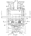
- moulding trays to be loaded with lumps of clay are indicated at 1.
- the moulding trays each contain sixteen moulding cavities, which are marked a to p as seen from the left to the right in fig. 1.
- moulding trays or moulding tray supports respectively are e.g. swingably (about the longitudinal axis) mounted between the end walls of a conveyor drum which is mounted for rotation about a horizontal axis.
- the upper part of the motion path of this conveyor drum is indicated by the arc x.
- the four moulding trays 1 are each designating one of four successive positions or stations, in which the conveyor drum is coming to a standstill each time after carrying out a displacement step in the direction of the arrow y.
- the loading with lumps of clay is taking place in the positions I and II.
- the extruding device used in the example shown comprises two row A and B of four presses each, the drive motors of which are indicated at A1 to 4 and B1 to 4 respectively.
- C indicates the bunkers to which the clay is supplied which has to be worked to mouldings, whereas D1 to 4 and E1 to 4 designate the eight extruding nozzle units.
- a depositing means F or G respectively Under each of the eight extruding nozzle units there is provided a depositing means F or G respectively, each of which consists of two vertically arranged endless conveyor belts, which are driven with the opposing runs moving downwardly.
- the drive means for these depositing means have been indicated at A and J respectively in fig. 1.
- the four depositing belts F1 to 4 are positioned vertically over a moulding tray within station I, while the depositing belts G1 to 4 are located vertically over the moulding tray within station IV.
- the entire extruding device comprising the individual presses A and B with the respective drive means A1 to 4 and B1 to 4, the clay bunkers C, the extruding nozzle units D1 to 4 and E1 to 4, as well as the depositing belts F1 to 4 and G1 to 4 with the respective drive means are mounted within a frame K, which is swingably suspended, about a horizontal axis L, between lateral supports M of a stationary supporting structure, of which a gangway N is also making a part.
- Fig. 1 shows the swingable frame with the extruding device in a mid position. This mid position corresponds with the mid position of the eccentric-connecting rod mechanism, indicated at O, by means of which the movable frame may carry out a complete swinging motion each time during a period of standstill of the conveyor drum and the moulding trays carried thereby.
- the depositing mouths of the depositing belts F1 to 4 are located over the partitions between the moulding cavities c and d or g and h or k and l or o and p respectively.
- the depositing belts G1 to 4 which are located behind the plane of drawing in fig. 1, are (in the mid position under consideration) located respectively over the partition between the moulding cavities a and b or e and f or i and j or m and n respectively.
- the depositing belts G are located offset relative to the depositing belts F through a distance corresponding to the pitch of the moulding cavities.
- the various drive means are timed with respect to one another in such a way, that within each period of standstill of the conveyor drum the excentric-connecting rod mechanism O is performing a complete swinging movement, during which each press produces two lumps of clay, which are successively ejected by the respective depositing belt. From the mid position in fig.
- the movable frame K is first moving to the left, towards a position vertically over the moulding cavities c, g, k and o within station I and the moulding cavities a, e, i and m within station IV respectively, and then - after each of the moulding cavities just referred to having received a lump of clay - to the right towards a position vertically over the moulding cavities d, h, l and p within station I and the moulding cavities b, f, j and n within station IV respectively, and finally, after the last mentioned cavities having also been loaded with lumps of clay, back to the said mid position, where it comes to a standstill. Thereafter the conveyor drum will perform a further displacement step. It will be clear, that in this way a moulding tray, which has received the first eight lumps of clay in station I, will receive its second eight lumps of clay in station IV, which is three displacement steps later.
- a drum is used as a conveying means for the stepwise displacement of the moulding trays to be loaded. It will be understood however, that the device according to this invention is also applicable in a case, in which the moulding trays are displaced from station I to station IV along a straight path.
Landscapes
- Engineering & Computer Science (AREA)
- Manufacturing & Machinery (AREA)
- Chemical & Material Sciences (AREA)
- Ceramic Engineering (AREA)
- Mechanical Engineering (AREA)
- Press-Shaping Or Shaping Using Conveyers (AREA)
- Devices For Post-Treatments, Processing, Supply, Discharge, And Other Processes (AREA)
- Special Conveying (AREA)
- Attitude Control For Articles On Conveyors (AREA)
Claims (2)
- Vorrichtung zur Bearbeitung einer Tonmenge zu einzelnen, in nebeneinander liegenden Formkammern (a-p) eines Formkastens (1) abzulegenden Formlingen, welche Vorrichtung einen Rahmen (K) mit mindestens einer durch diesen getragenen Presse (D; E) und Mittel (F; G) zum Einlegen von Tonblöcken, mit zusammenarbeitenden, im Rahmen (K) in einer Position unterhalb der Presse (D; E) angeordneten Führungsrollen aufweist, welche Vorrichtung an einer Formkasten-Füllstation angeordnet ist in einer Stellung über einer Vorrichtung zum intermittierenden Zuführen von Formkasten (1) mit deren Längsachsen quer zur Förderrichtung gerichtet, dadurch gekennzeichnet, dass der Rahmen (K) um eine oben liegende waagerechte Achse (L) schwenkbar an einem stationären Traggerüst (M, N) aufgehängt ist, wobei Antriebsmittel (O) vorgesehen sind, mittels welcher der Rahmen (K) in eine Schwenkbewegung um eine Mittellage versetzt werden kann, in der Weise, dass während jeder Schwingperiode zwei aufeinanderfolgende Formlinge durch die Ablegevorrichtung (F; G) in zwei angrenzende Kammern (a, b; c, d ...) des stillstehenden Formkastens (1) abgelegt werden können.
- Vorrichtung nach Anspruch 1, dadurch gekennzeichnet, dass die Antriebsmittel (O) ein am schwenkbaren Rahmen (K) montierter bezw. am stationären Traggerüst (M, N) montierter Exzenter-Triebstangen-mechanismus umfassen.
Applications Claiming Priority (2)
| Application Number | Priority Date | Filing Date | Title |
|---|---|---|---|
| NL8901771 | 1989-07-10 | ||
| NL8901771A NL8901771A (nl) | 1989-07-10 | 1989-07-10 | Inrichting voor het persen van een voorraad klei tot afzonderlijke, in een vormbak te deponeren vormlingen. |
Publications (2)
| Publication Number | Publication Date |
|---|---|
| EP0408149A1 EP0408149A1 (de) | 1991-01-16 |
| EP0408149B1 true EP0408149B1 (de) | 1993-04-21 |
Family
ID=19855012
Family Applications (1)
| Application Number | Title | Priority Date | Filing Date |
|---|---|---|---|
| EP90201883A Expired - Lifetime EP0408149B1 (de) | 1989-07-10 | 1990-07-10 | Vorrichtung zum Pressen zugeführten Tons in einzelne in einem Formkasten abzulegende Formlinge |
Country Status (7)
| Country | Link |
|---|---|
| US (1) | US5131831A (de) |
| EP (1) | EP0408149B1 (de) |
| AU (1) | AU629382B2 (de) |
| DE (1) | DE69001406T2 (de) |
| ES (1) | ES2040034T3 (de) |
| NL (1) | NL8901771A (de) |
| WO (1) | WO1991000794A1 (de) |
Families Citing this family (6)
| Publication number | Priority date | Publication date | Assignee | Title |
|---|---|---|---|---|
| NL9400663A (nl) * | 1994-04-25 | 1995-12-01 | Boer Beheer Nijmegen Bv De | Inrichting voor het vervaardigen van vormlingen. |
| NL9401648A (nl) * | 1994-10-06 | 1996-05-01 | Boer Beheer Nijmegen Bv De | Inrichting voor het vervaardigen van vormlingen voor de steenproduktie. |
| NL9401674A (nl) * | 1994-10-11 | 1996-05-01 | Boer Beheer Nijmegen Bv De | Inrichting voor het vervaardigen van vormlingen uit klei voor de steenproduktie. |
| NL193794C (nl) * | 1994-12-22 | 2000-11-06 | Beheermij De Boer Nijmegen Bv | Inrichting voor de vervaardiging van vormlingen uit klei voor de steenproductie. |
| US6468065B1 (en) | 1999-09-29 | 2002-10-22 | Anvil Iron Works, Inc. | Brick molding apparatus |
| CN105437363A (zh) * | 2015-12-24 | 2016-03-30 | 益阳橡胶塑料机械集团有限公司 | 制砖机布料小车的拨料装置 |
Family Cites Families (13)
| Publication number | Priority date | Publication date | Assignee | Title |
|---|---|---|---|---|
| US457381A (en) * | 1891-08-11 | Brick machine | ||
| US2389163A (en) * | 1942-05-14 | 1945-11-20 | Miller Pottery Engineering Co | Apparatus and method for feeding clay to cavitous jigger molds |
| US2494112A (en) * | 1945-02-12 | 1950-01-10 | Miller Pottery Engineering Co | Apparatus for making mold charges from plastic ceramic materials |
| DE2128666A1 (en) * | 1971-06-09 | 1972-12-28 | Winkler & Dünnebier, Maschinenfabrik und Eisengießerei KG, 5450 Neuwied | Sugar casting machine - for multiple sweetmeat casting into moulds using hydraulic control system |
| NL161832C (nl) * | 1973-11-07 | 1980-03-17 | Hubert & Co Maschf | Inrichting voor het vervaardigen van vormlingen. |
| NL7603794A (en) * | 1976-04-09 | 1977-10-11 | Mattijssen Bv Maschf | Forming process for clay or other kneadable material - has belt feed system and several rotary bosses on cylindrical axles |
| US4708621A (en) * | 1985-12-27 | 1987-11-24 | Hawkeye Concrete Products Co. | Concrete pipe making machine |
| AU1693088A (en) * | 1987-05-29 | 1988-12-01 | Brokers Inc. Pty. Ltd. | Compacting machine |
| NL8802564A (nl) * | 1988-10-18 | 1990-05-16 | Sneek Hubert Maschf | Afstrijkinrichting voor een baksteenvorminrichting. |
| NL8802567A (nl) * | 1988-10-18 | 1990-05-16 | Sneek Hubert Maschf | Strengophouder voor steenvormmachine. |
| NL8802568A (nl) * | 1988-10-18 | 1990-05-16 | Sneek Hubert Maschf | Vormbakkenmontage voor een baksteenvorminrichting. |
| NL8802566A (nl) * | 1988-10-18 | 1990-05-16 | Sneek Hubert Maschf | Inrichting voor het vormen van baksteenvormlingen. |
| NL8802565A (nl) * | 1988-10-18 | 1990-05-16 | Sneek Hubert Maschf | Zandaandrukrollen voor steenvormmachine. |
-
1989
- 1989-07-10 NL NL8901771A patent/NL8901771A/nl not_active Application Discontinuation
-
1990
- 1990-07-10 ES ES199090201883T patent/ES2040034T3/es not_active Expired - Lifetime
- 1990-07-10 AU AU60606/90A patent/AU629382B2/en not_active Ceased
- 1990-07-10 DE DE90201883T patent/DE69001406T2/de not_active Expired - Fee Related
- 1990-07-10 EP EP90201883A patent/EP0408149B1/de not_active Expired - Lifetime
- 1990-07-10 WO PCT/NL1990/000095 patent/WO1991000794A1/en not_active Ceased
-
1991
- 1991-03-08 US US07/635,125 patent/US5131831A/en not_active Expired - Fee Related
Also Published As
| Publication number | Publication date |
|---|---|
| EP0408149A1 (de) | 1991-01-16 |
| AU629382B2 (en) | 1992-10-01 |
| US5131831A (en) | 1992-07-21 |
| NL8901771A (nl) | 1991-02-01 |
| DE69001406D1 (de) | 1993-05-27 |
| DE69001406T2 (de) | 1993-10-28 |
| ES2040034T3 (es) | 1993-10-01 |
| WO1991000794A1 (en) | 1991-01-24 |
| AU6060690A (en) | 1991-02-06 |
Similar Documents
| Publication | Publication Date | Title |
|---|---|---|
| US6834755B2 (en) | Conveying machines | |
| US12059009B2 (en) | Transport system for an industrial confectionery machine | |
| US3435940A (en) | Mechanism for the formation of orderly groups of cigarettes | |
| US3750232A (en) | Molding apparatus | |
| US4068993A (en) | Apparatus for moulding confectionery | |
| JPH0135726B2 (de) | ||
| US5096041A (en) | Method and apparatus for receiving and delivering articles with differing motion characteristics | |
| KR100843809B1 (ko) | 제과 성형체 제조용 베이킹 오븐 | |
| US5180602A (en) | Method and apparatus for controlled molding of chocolate shell goods and the like | |
| EP0408149B1 (de) | Vorrichtung zum Pressen zugeführten Tons in einzelne in einem Formkasten abzulegende Formlinge | |
| US4192415A (en) | Apparatus for transferring frozen confections from a supply conveyor to a discharge conveyor | |
| US3677686A (en) | Apparatus for advancing pallets for making tiles | |
| GB2275679A (en) | Hopper exit for cigarettes | |
| CA1048725A (en) | Machine for producing hollow plastic articles with blowing mould closing unit | |
| EP0300530B1 (de) | Vorrichtung für die geordnete Zusammenstellung und Schaffung eines Sammelvorrats für konische Behälter in Verpackungsanlagen | |
| EP1270459B1 (de) | Einheit zum Zuführen von Produkten in einer geordneten Reihenfolge zu einer Entladestation | |
| US5079022A (en) | Mold displacement method for fixed surface type forming machine | |
| EP0688651A1 (de) | Spritzgiessmaschine und Verfahren zur Herstellung von Hohlkörpern aus Kunststoff | |
| US3590748A (en) | Moulding apparatus | |
| EP0509624A2 (de) | Fördereinrichtung für Konfektprodukte mit konstanter Geschwindigkeit der Aufnahme und Ausgabe-Sektionen | |
| US4207044A (en) | Apparatus for automatically cutting and feeding wafer biscuits and like products to movable moulds | |
| WO1996038276A1 (en) | Apparatus for manufacturing green bricks from clay for the production of bricks | |
| GB2062567A (en) | Apparatus for handling rod-like articles | |
| US1840438A (en) | Automatic continuous molding machine | |
| US3315783A (en) | Article conveying apparatus |
Legal Events
| Date | Code | Title | Description |
|---|---|---|---|
| PUAI | Public reference made under article 153(3) epc to a published international application that has entered the european phase |
Free format text: ORIGINAL CODE: 0009012 |
|
| AK | Designated contracting states |
Kind code of ref document: A1 Designated state(s): BE DE DK ES FR GB IT NL SE |
|
| 17P | Request for examination filed |
Effective date: 19910716 |
|
| RAP1 | Party data changed (applicant data changed or rights of an application transferred) |
Owner name: BEHEERMAATSCHAPPIJ DE BOER NIJMEGEN B.V. |
|
| 17Q | First examination report despatched |
Effective date: 19920623 |
|
| GRAA | (expected) grant |
Free format text: ORIGINAL CODE: 0009210 |
|
| AK | Designated contracting states |
Kind code of ref document: B1 Designated state(s): BE DE DK ES FR GB IT NL SE |
|
| PG25 | Lapsed in a contracting state [announced via postgrant information from national office to epo] |
Ref country code: SE Effective date: 19930421 Ref country code: DK Effective date: 19930421 |
|
| REF | Corresponds to: |
Ref document number: 69001406 Country of ref document: DE Date of ref document: 19930527 |
|
| ET | Fr: translation filed | ||
| ITF | It: translation for a ep patent filed | ||
| REG | Reference to a national code |
Ref country code: ES Ref legal event code: FG2A Ref document number: 2040034 Country of ref document: ES Kind code of ref document: T3 |
|
| PLBE | No opposition filed within time limit |
Free format text: ORIGINAL CODE: 0009261 |
|
| STAA | Information on the status of an ep patent application or granted ep patent |
Free format text: STATUS: NO OPPOSITION FILED WITHIN TIME LIMIT |
|
| 26N | No opposition filed | ||
| PGFP | Annual fee paid to national office [announced via postgrant information from national office to epo] |
Ref country code: FR Payment date: 19950619 Year of fee payment: 6 |
|
| PGFP | Annual fee paid to national office [announced via postgrant information from national office to epo] |
Ref country code: ES Payment date: 19950628 Year of fee payment: 6 |
|
| PGFP | Annual fee paid to national office [announced via postgrant information from national office to epo] |
Ref country code: GB Payment date: 19950707 Year of fee payment: 6 |
|
| PGFP | Annual fee paid to national office [announced via postgrant information from national office to epo] |
Ref country code: BE Payment date: 19950712 Year of fee payment: 6 |
|
| PGFP | Annual fee paid to national office [announced via postgrant information from national office to epo] |
Ref country code: DE Payment date: 19950726 Year of fee payment: 6 |
|
| PGFP | Annual fee paid to national office [announced via postgrant information from national office to epo] |
Ref country code: NL Payment date: 19950728 Year of fee payment: 6 |
|
| PG25 | Lapsed in a contracting state [announced via postgrant information from national office to epo] |
Ref country code: GB Effective date: 19960710 |
|
| PG25 | Lapsed in a contracting state [announced via postgrant information from national office to epo] |
Ref country code: ES Free format text: LAPSE BECAUSE OF NON-PAYMENT OF DUE FEES Effective date: 19960711 |
|
| PG25 | Lapsed in a contracting state [announced via postgrant information from national office to epo] |
Ref country code: BE Effective date: 19960731 |
|
| BERE | Be: lapsed |
Owner name: BEHEERMAATSCHAPPIJ DE BOER NIJMEGEN B.V. Effective date: 19960731 |
|
| PG25 | Lapsed in a contracting state [announced via postgrant information from national office to epo] |
Ref country code: NL Effective date: 19970201 |
|
| GBPC | Gb: european patent ceased through non-payment of renewal fee |
Effective date: 19960710 |
|
| PG25 | Lapsed in a contracting state [announced via postgrant information from national office to epo] |
Ref country code: FR Effective date: 19970328 |
|
| NLV4 | Nl: lapsed or anulled due to non-payment of the annual fee |
Effective date: 19970201 |
|
| PG25 | Lapsed in a contracting state [announced via postgrant information from national office to epo] |
Ref country code: DE Effective date: 19970402 |
|
| REG | Reference to a national code |
Ref country code: FR Ref legal event code: ST |
|
| REG | Reference to a national code |
Ref country code: ES Ref legal event code: FD2A Effective date: 19970811 |
|
| PG25 | Lapsed in a contracting state [announced via postgrant information from national office to epo] |
Ref country code: IT Free format text: LAPSE BECAUSE OF NON-PAYMENT OF DUE FEES;WARNING: LAPSES OF ITALIAN PATENTS WITH EFFECTIVE DATE BEFORE 2007 MAY HAVE OCCURRED AT ANY TIME BEFORE 2007. THE CORRECT EFFECTIVE DATE MAY BE DIFFERENT FROM THE ONE RECORDED. Effective date: 20050710 |