EP0408224A2 - Rechnerische Methoden und elektronische Kameravorrichtung zur Bestimmung der Entfernung von Objekten, zum schnellen Autofokussieren und um eine verbesserte Bildschärfe zu erreichen - Google Patents
Rechnerische Methoden und elektronische Kameravorrichtung zur Bestimmung der Entfernung von Objekten, zum schnellen Autofokussieren und um eine verbesserte Bildschärfe zu erreichen Download PDFInfo
- Publication number
- EP0408224A2 EP0408224A2 EP90307146A EP90307146A EP0408224A2 EP 0408224 A2 EP0408224 A2 EP 0408224A2 EP 90307146 A EP90307146 A EP 90307146A EP 90307146 A EP90307146 A EP 90307146A EP 0408224 A2 EP0408224 A2 EP 0408224A2
- Authority
- EP
- European Patent Office
- Prior art keywords
- image
- camera
- distance
- parameters
- surface patch
- Prior art date
- Legal status (The legal status is an assumption and is not a legal conclusion. Google has not performed a legal analysis and makes no representation as to the accuracy of the status listed.)
- Granted
Links
Images






Classifications
-
- G—PHYSICS
- G01—MEASURING; TESTING
- G01C—MEASURING DISTANCES, LEVELS OR BEARINGS; SURVEYING; NAVIGATION; GYROSCOPIC INSTRUMENTS; PHOTOGRAMMETRY OR VIDEOGRAMMETRY
- G01C11/00—Photogrammetry or videogrammetry, e.g. stereogrammetry; Photographic surveying
- G01C11/02—Picture taking arrangements specially adapted for photogrammetry or photographic surveying, e.g. controlling overlapping of pictures
-
- G—PHYSICS
- G01—MEASURING; TESTING
- G01C—MEASURING DISTANCES, LEVELS OR BEARINGS; SURVEYING; NAVIGATION; GYROSCOPIC INSTRUMENTS; PHOTOGRAMMETRY OR VIDEOGRAMMETRY
- G01C3/00—Measuring distances in line of sight; Optical rangefinders
- G01C3/02—Details
- G01C3/06—Use of electric means to obtain final indication
- G01C3/08—Use of electric radiation detectors
-
- H—ELECTRICITY
- H04—ELECTRIC COMMUNICATION TECHNIQUE
- H04N—PICTORIAL COMMUNICATION, e.g. TELEVISION
- H04N13/00—Stereoscopic video systems; Multi-view video systems; Details thereof
- H04N13/20—Image signal generators
- H04N13/204—Image signal generators using stereoscopic image cameras
- H04N13/207—Image signal generators using stereoscopic image cameras using a single two-dimensional [2D] image sensor
- H04N13/236—Image signal generators using stereoscopic image cameras using a single two-dimensional [2D] image sensor using varifocal lenses or mirrors
-
- H—ELECTRICITY
- H04—ELECTRIC COMMUNICATION TECHNIQUE
- H04N—PICTORIAL COMMUNICATION, e.g. TELEVISION
- H04N13/00—Stereoscopic video systems; Multi-view video systems; Details thereof
- H04N13/20—Image signal generators
- H04N13/271—Image signal generators wherein the generated image signals comprise depth maps or disparity maps
Definitions
- the present invention relates to electronic camera apparatus and methods based on signal processing techniques for (i) determining the distance of objects from a camera system, (ii) rapid autofoeusing of camera systems, and (iii) obtaining improved focus images from blurred images.
- this invention relates to system parameter estimation and signal resloration in any linear shifl-invarianl system, i.e., a system that performs convolution operation on the input signal.
- a common techuique of finding the distance of an object from a caunera involves focusing the objects's image on the image detector. The distance is then determined from Lhe camera setting. This technique is called depth-from-focusing.
- depth-from-focusing A comparative study of different depth-from-focusing methods is reported by E. Kotkov in all article titled "Focusing" in the Oetober 1987 issue of International Journal of Computer Vision, Volume 1, No, 3, pages 223-238.
- the depth-from-focusing techaique involves (i) acquiring a large number (about 20 or more) of images for different, camera settings, (ii) computing a focus meanure for each of these images, and, (iii) determining the image for which the focus measure is a maximum and determining distance from the corresponding camera setting.
- the major drawbacks of this techique are (i) it is very slow because it involes acquiring many images fur different camera settings, and (ii) it requires large computational resources in terms of memory space and processing power.
- the first method of Pentland uses a sinle image of an object.
- the object must contain a bright surface patch adjacent to a dark surface patch with a common straight border in between.
- Such au object produces a straight edge which is a step discontinuity in the focused image.
- a closely rolated method is disclosed by P. Grossman in a paper tiLled “Depih from Focus” published in Pallind Recognilion Lellers, Vol. 5, pages 63-69, Jan. 1987.
- a muclt improved and more general version of these same methods is dis-dosed by this inventor in a paper titled "Depth Recovery from Blurred Edges," published in the Proceedings of IEEE Computer Sociely conference on Computer Vision and Pattern Recognition, June 1988, pages 498-503.
- objects having bright and dark surface patches willi a common straight border in between arc rare in this world. Therefore it is not applicable in most cases.
- the second method of Pentland is based on comparing two images, one image formed with a very small (pin-hole) aperture and the other image formed with a normal aperture.
- Application of this method poses some serious practical difliculties.
- a very small aperture increases the effects of diffraction which distorts the image. Further, a smaller aperture gathers lesser light and therefore increases exposure period.
- the present invention advances technology lifr rapid autofocusing of electronic cameras, It has been known to autofocus cameras by several methods.
- One method for autofocusing has been disclosed in Japanses Patent No, 62284314 dated 1087. This method is believed to be incorrect in theory, inac-curate, and, consequently, or limited use in practice because of the following reasons.
- the method disclosed in the '314 Japanese Patent involves moving the lens with respect to a fixed object. Therefore, the correspondence between the two images of a point object, e.g., the first image taken before moving the lens and the second image taken after moving the lens, cannot be established. This problem, which is referred to as correspondence problem, is well known sterco-vision.
- the method set forth in the '314 Japanese disclosure docs not provide a magnification correction sLep so that errors are introduced into the process.
- the method refarred to above is very restricted in scope since iL involvers changing only one camera parameter -- the position or the lens.
- a previous method and apparatus for linding the distance of objects and autofocusing has been disclosed by the saiiic inventor in commonly-owaed copending U. S. Patent Application Serial No. 126,107 filed on November 27, J087.
- the previous method involves processing two images of an object, the images being acquired with different camera settings.
- the camer seLLing differs in any of the three camera parameters: (i) position of the image detector, (ii) focal length of the camcra system, and (iii) diameter of the camera's aperture.
- Two constraints which are mathematical expressions (i.e. binding relations), were then formulated. The first constraint was expressed solely in terms of the two observed images, while the second constraint was expressed solely in terms of the known camera parameter values and camera characteristics.
- This earlier method characterized the Point Spread Function (PSF) by a single intermediate parameter, ⁇ , which is the standard deviation of the PSF. This is an inadequate characterization in the presence of diffraction and leas aberrations.
- PSF Point Spread Function
- ⁇ the standard deviation of the PSF.
- the previous systen set forth by the inventor in his copending application requires that means be provided in the camera system for measuring the camera parameters.
- the previous system does noL consider the spectral content of the light as a parameter. Morcovcr, the previous system does not provide for performing uncertainly analysis or error propagation analysis during processing, nor was it applicable to every linear shift-invariant system for eslimating a number of system parameters.
- n is, therefore, an object of the present invention to provide a depth-from-focusing approach which involves the acquisition and processing of only two images.
- Lo provide an approach which ia applicable Lo all linear shift-invariant systems.
- Yet another object of the present invention is to provide a simpter and less expensive apparatus for the processing of lwo images to determine both object distance and camera parameters.
- AnoLher object of the present invention is to eliminate the need for an intermediate parameter to characterize the Point Spread Function of the camera system. Another object of the present invention is to climinate the need for quantilatively measuring the parameters in the camera apparatus.
- Another object of the present invention is to provide the means for a single calcula-Lion or process step to determine the distance of objects, the optical transfer function, and/or camera parameter values.
- An additional object of the present invention is to provide a means for considering the spectral content of the light as it relates to the camera parameters.
- Another object of the present invention is to provide rapid autofocusing of electronic cameras, and obtaining improved-focus images from blurred images.
- Another object of the present invention is a method for estimating system parameters and recovering input signal in any instrument that can be modeled as it linear shift-invariant system, i.e., a system that performs convolution operation.
- the present invention is a process and apparatus for determining the distance of a surface patch of an object from a camera system, focusing the camera system as a result of the determination of the distance, determining camera system parameters, and obtaining improved focus image of a surface patch from its respective blurred image.
- This invention includes a camera system having an image detector such as CCD array, photographic film, etc., which records the image.
- the camera has an aperture through which light enters the camera system from the scene, a light filter which allows a known spectrum (or color) of light to pass through and form an image on the image detector, and all image forming optical system having lenses or mirrors or both.
- the image forming optical system includes a first and second principal plane and focal length, the second principal plane being closer to the image detector than the first principal plane.
- the image formation process of the camera system depends on at least one, and possibly more, of the following camera parameters: (i) the distance between the second principal plane and the image detector, (s), (ii) the diameter (D) of the camera aperture, (iii) the focal length (/ ) of the image forming optical system, and (iv) the spectral characteristies ( ⁇ ) of light entering the camera system.
- the camera system provides means for varying the value of at least one, and possibly more, and even all, of the camera parameters. This feature is used to change the camera setting by varying the value of at least one, and possibly more, and eveu all, of the camera parameters.
- the method of the present invention involves processing at least two, and possihly more, images of a surface patch of an object, acquired with different camera settings to find the distance of the surface pathch from the camera system.
- the image processing computer further includes a memory spare in which a table of values characterizing the camera system in prestored. This table is used Lo lind the distance of Lhe surface patch.
- the computer can further include a special purpose VLS1 computer processing hardware which searches for a set of given values in the prestored table.
- the computer may include a special purpose VLS1 computer processing hardware for computing a correlation measure between a scL of given values and the prestored table of values, and for determining Lhe position in the Lablc that results in maximum currela-tion. The position in the table where Lhe search succeeds or where the correlation is maximum gives the distance of Lhe surface patch.
- the effective camera aperture is provided by an aperture stop placed at the front of and close to the image forming optical system, whereby the entrance pupil of the camera system remains the same for all objects in the field-of-view of the camera system.
- the means for changing the camera parameters of the camera system is provided in a manner such that position of the entrance pupil of the camera system remains unchanged when one or more camera parameters arc changed. This helps to avoid the correspondence problem encountered in stereo-vision.
- An alternative embodiment of the camera system is obtained by a minor modification of the preferred embodiment described above.
- multiple cameras are used. These multiple cameras are such that the camera parameter values of each individual camera differs in at least one, and possibly more, and even all, of the camera parameters. That is, no two cameras among the multiple cameras have identical camera parameter values for all camera parameters.
- This apparatus there is no necessity to provide for varying any of the camera parameters of the individual cameras. All camera parameters of each canmera can be fixed, thus avoiding the necessity for any moving parts in the camera system. Therefore the apparatus can be made rugged.
- Each camera is used to acquire one image corresponding to one set of the values of camera parameters.
- Each of the individual cam-cras view the scene through a common aperture with the aid of a beam-splitting arragne-ment. Except for the above differences, the alternative embodiment is similar to the preferred embodiment.
- the method of the present invention includes setting a camera Lo a first set of camera parameters including at least one of (i) the distance between the second principal plane and the image detector (s), (ii) the diameter (D) of the camera aperture, (iii) the focal length (f) of the camera system, and (iv) spectral characteristics (X) of light transmitted by the light filter.
- These set of camera parameters can be expressed as a sin-) gle vector (c a ) as set forth below:
- the first image can be extracted from the image detector by converting it to a first set of values for processing in the image processing system. This processing can be accomplished in real time simultaneously wiLh processing of other image values or can bestored for later processing.
- the camera is set to a second camera setting exprcssed as set forLh below: such that c, docs not equal c a2 .
- This can be done by merely changing at least o,ic of the camera parameters, such as, for example, the distance s.
- NcxL a second image of the same surface patch is formed on Lhe image detector. This is then converted to a set of values for processing in the image processing system.
- each of the sets of the values are processed and converted to normalized image raiues related Lo the l'oint Spread Function of the camera system by a convolution operation.
- the theorclient under pinnings of the present invention is expressed by carrying out preprocessing operations on the recorded image.
- These preprocessing operations decouple (or separate) the effects of (i) the focused image of a surface patch in the scene, (ii) the over-all brightness of the surface patch, and (iii) the distance of the surface patch, and the camera specified by a-sel of camera parameters. Having decoupled Lhe effects or these three factors on the image of a surface patch, the effects or (i) the focused image and (ii) the over-all brightness are cancelled by comparing two images or the same surface patch obtained wiLh different camera settings.
- This operation gives rise Lo a single constraint on the distance of the surface patch. This constraint can be solved either analytically or using a prestored table iu computer memory provided in the image processor Lo obtain Lhe distance of the surface pathc.
- the "focused image" of the surface patch has been defined in terms of Llte lightenergy incident on the entrauce pupil of the camera system from points oil the surface patch along different directions of view, buL independent of actual distance of the surface patch.
- the brightness of the focused image of a surface patch along a given direction can be defined as proportional Lo the total light energy per unit time incident on the entrance pupil of the camera system from Llu: object, point on the surface' paLch along the given direction. This definition of focused image is different from that found in the literature. It has been defined uniquely here in terms of the energy incident, on the entrance pupil rather than the brightness or radiance of the object points on the surface patch.
- This unique definition is necessary Lo decouple the effects of actual distance or the surface patch and its focused image. Consequently, this definition is useful for providing all exael theoretical basis for preprocessing the signal. Moreover, further development of signal processing can be performed from a sound theoretical basis.
- the image formation process in the camera system is characterized by defining Lhe term "normalized focus image" of the surface patch only in Lcrms of the focused image as defined above, but independent of actual values of any camera parameters.
- the normalized focus image is defined as the focused image with unit average brightness and unit magnilication. This definition decouples the effect of (i) the over-all brightness of the surface pathc (because the average brightness is fixed Lo be one uniL), (ii) Lhe camera parameter values, and (iii) the focused image of the surface patch.
- the preprocessing operation is performed to obtain a simple relation between a preprocessed image and the normalized focused image defined carlier in terms of camera parameter values.
- one or more of the following operations arc included ;
- the present invention evokes a relation established between a suitably preprocessed image (as defined above) of the same surface patch in terms of camera parameters by convolving the normalized focused image of the surface patch with a characteristic Point Spread Function.
- This is referred to as the "convention relation”.
- the Point Spread Function is determined by the actual values of Lhe camera parameters and the distance of the surface patch, hu does not depend on the focused image of the surface patch.
- the image formation process is characterized in terms of a set of camera parameters.
- the normalized focus image contains only the photometric information about Lhe surface patch
- the Point Spread Function contains geometric information (i.e., information regarding distance) of the surface patch and camera information (i.e., information about the camera parameters).
- the convolution relation is expressed as the Fourier transform of the preprocessed image being equal to the product of the Optical Transfer Function of the camera system, II( ⁇ , ⁇ ;c a ,r 0 ), and the Fourier Lrallsform F n ( ⁇ , ⁇ ) of the normalized focused image of the surface patch.
- the optical transfer function is Lhe Fourier transform of the camera's point spread funcLion h(x,y;e a ,r 0 ).
- the optical transfer function therefore, is determined and dependent on the the camera parameters and the distance of the surface patch.
- An analytic expression can be derived for the pot- ical transfer function from a theoretical model of the image formation theory in the camera system. For example, an image formation theory based on the principles of paraxial geornetrie optics, or dillraclion optics can be used.
- the retalion oblaiued above between a suilably preprocessed image and the normalized foeuaed image is used Lu sperify a relation between Lwo images.
- One image is the result of lirst recording :m image in the specilied fileld of view by selling the camera system Lo the first camera setting and then processing the image thus reeorded according to the preprocessing operations speeilied for the firsl camera setting.
- the other inage is the resull or reeording au image in the same field of view by setting the camera system to said second camera selling and then processing the image thus reeorded according Lo the preprocessing operations speeilied for the aceond camera setting.
- This relation between 1 the Lwo images is expressed for all possible distanees of the surface patch directly in terins of the lirst eamera setting and the seeond camera aetting. No interinediate parameters are used in this relation. Further, this relation is expressed independent of appearance or focused image of the surface pateh. In faet since the normalized foensed image should be Lhe same for all distances, the term corresponding Lo the normalized focused image in the relation derived earlier between a suitably preprocessed image and the normalized foeused image is eliminated.
- This relation faeilitates the determination of the distance of the surface patch in a computationally ellicient mauner by solying a single constraint evne in the presence of significant optical aberraLions using camera. systems having arbitraty point spread functions without actually measuring the camera parameLers and without introducing unueecssary restrictions, approximations; and intermediate parameters.
- a spccilic exantple of the Lhe relation specilled by the previous paragraph can be obtained as follows. Record the first image of the surface pateh fur a lirst position of the image detector, move the image detector to a new posiLion while keeping everything else (i.e. all other camera parameters) Lhe same, and record a sceond image of the surface patch. Preprocess the first and Lhe second recorded images and Lake the ration of their Fourier transforuns, i.c. This gives a relation that equates the ratio of the Fourier transforms of the two preprocessed images to the ratio of the corresponding optienl transfer funetions.
- the Fourier transform of the uormalized foeused image caneels ont. Therefore, at any given Fourier spatial frequeney, the value of the ratio depends on the the distanee of said aurface pateh but not on the nornutlized foeused image.
- This ration can be expressed as a funetion of the distance of the surface patch in the form of an analytie equation, e.g., or tabulated and stored in computer memory for all possible distances of the object.
- the analytic expression can be derived from a theoretical model of the camera system. For example, the analytic expression can be derived based on Llic principles of geometric opties, or diffraction optics. This analytie expression can be used to determine the din-Lance of Lhe surface pateh.
- the ratio relation obtained above can also be represented as a prestored table of valucs in computer memory. This table can then be used to determine the distance of the surface pateh.
- the table itself can be computed from a theorctieal model of the camera system.
- the table can also be determined experimentally by a ealibration procedure.
- the second major stcp comprises the following steps.
- the relation used in this step is the one spceified earlier between two images.
- one image is the rcsmt of lirst recording an image in the spceilied lield of view by sctting the camera system to the lirst camera setting and then processing the image thus recorded according to the preproccssing operations specilied for the lirst camera setting.
- the other image is the result of first recording another image in the same lield of view by setting Lhe camera system to Lhe second camera seLLing and then processing the image thus rceorded according to the preprocessing operations specified for Lhe second camera selLing,
- Lo a method for finding Lhe distance of a surface patch
- the present invention also provides all expression Lo determine the uncertainty in the distanee of the surface pateh determined by the method outlined above. This expression involves the optical transfer funetion of the camera system, , the uncertainty in the measurement of camera parameter values, and Lhe uncertainty in the measurement of image signal exprcssed as signal Lo noise ratio.
- Cor determining distance can be enhanced by reducing the effects of blur seeping across Lhe borders of the image of the surface patch (Lhe image-overlap problem).
- the region surrounding the border of Lhe surface patch is kept dark by not illuminating the region. This avoids the overlapping of blur produced by surface patches adjacent to the surface patch with Lhe blur produced by the surface patch. Hence the accuracy of Lhe distance computed improves.
- brightness variation can be introduced hy projecting a light pattern onto the surface patch in the scene. This facilitates the determination of distance of the surface patch.
- acquiring and processing just Lwo images of a surface patch arc sufficient to determine the distance of the surface patch.
- a more robusL estimate of Lhe distance can be obtained hy processing serveral distinet pairs of images of the surface patch.
- Each disLincL pair of images is processed Lo obtain one independent estimate of distance.
- a weighted average of all Lhe independent estimates of distances yietds a robust estimate of distance.
- the disLance of the surface patch estimated by the above described method can be combined with other independent distance estimates (obtained by either the same method or a different method) by taking a weighted average to obtain a more robust estimate of the distance.
- Another feature of the present. invention is a method for rapidly autoforcusing a surface patch ou the image detector of the camera system using the distance determined between the camera system and the surface patch.
- this method includes Lwo more steps.
- the determination of these Lwo parameters is done using an image focusing formula.
- the next step in autofucusing is to set the values of Lhe focal length and the dia-Lance of the image detector from the second principal planc to Lhe values determined in the previous step. This accomplishes autofocusing.
- a further embodiment of the present invention is to facilitate determining in paral-
- the prcscnL invention is also used Lo determine improved-focus image of a surface patch from a pair of possibly blurred images recorded wiLh different camera settings.
- First the distance of the surface patch is determined by using the method outlined carlier. Based on this distance, the optical transfer function of one of the recorded and preprocessed image of Lhe surface patch, say the first image, is determined.
- the Fourier Lransform of the first image is then determined. This Fourier transform is divided (deconvolution) by the optical Lransfer function determined above. By computing the inverse Fourier transform of the result of the division above, all improved-locus image of the surface patch is obtained.
- This method includes the steps of dividing the complete field-of-view of Lhe camera system inLo many smaller subfield-of-views and repeating steps of the method of determining the improved-focus image of a surface patch for each subfield-of-view, thereby determining the improved focus images of surface patches in each subfield-of-view.
- the improved-focus images thus determined are then synthesized (or combined) to obtain all improved focus image of the entire scene in Lhe complete lield-of-view of the camera system.
- the present invention also includes an apparatus for determining the distance between a surface patch of an object from a camera system which includes :m image detector, a camera aperture, an image forming optical system having first and second principal planes and a focal length, the second principal plane being arranged cluser to the image detector than the first principal plane, and a light filter.
- the camera system also includes a camera controller which is operaLively connected to the parts of the camera system for movement Lo change one or more of the following camera parameters: i) Lhe distance between the second princ:ipal plane and the image detector, ii) the diameter of the camera aperture, and iii) the focal length of the image forming optical system.
- Lhe camera system also includes an image processor which is operatively connected Lo the image detector and Lo Lhe camera controller for receipt of signals from the image detector and for varying the camera parameLcrs by means of a camera controller.
- Lhe image processor includes means which convert Lite signal from the image detector Lo digital data and normalizes the resulting digital image for further image processing.
- a preprocessor can include aL least one of a means for correcting Lhe sensor-response characteristic of the image, means for correcting non-uniform lighL transmission of the image forming optical system, means for normalizing the brightness of the images, and means for normalizing magnification of the images recorded on the image detector.
- the image processor can also include a Fourier transformer of signals and a divider for dividing Fourier coolicients to provide a set of ratio values corresponding to signal from a first and a second image.
- This latter embodiment can also include a means for substituting ratiu values gathered from the first and second images into a mathematical relatioaship Lo provide the distance of the surface patch from the canera system.
- Yet another embodiment includes a look-up table and a correlation means Lo determine the distances of the object or objects from values obtained from a comparison of the input with values stored in the look-up table.
- the present invention provides a method of determining at Icast one and pussibly more unknown system parameters of a linear shift-invariant system, and also recovering the original input aignal Lo the lincar shift-invariant system.
- a lincar shift-invariant sys-tem is characterized by a system transfer function expressed in terms of a set of known system parameters which spccify the physical configuration of the system.
- the liecar shift-invariant system is such that it is capable of providing output signals fur different settings of the known system parameter values.
- the method for determining the unknown system parameters and Lite original input signal includes:
- a variation of tlm above method can be employed which consists of a number of linear shift-invariant systems instead of a single linear shift-invariant system.
- Each linear shift-iavariant system takes a common input signal and gives a distinct output aignal depending on its system parameters. The system parameters or each system is distinct.
- the problem is to determine those system parameters that are unknown and also to determine the common input signal given the output of all the systems,
- the system transfer function of the linear shift-invariant systems are characterized by the values of the system parameters. This method includes the steps of
- the present invention requires a processing of only two images. Therefore, it is faster and requires much less in the way of computational resources,
- the present invention is generally more applicable to practical camera systems, Furthermore, the present invention is not restricted to a (aussian Modulation Transfer Function. It is applicable to arbitrary Modulation Transfer Functions.
- the present system is applicable to any camera system that can be modeled as a Linear Shift-Invariant System. It is not restricted by the form of the Point Spread Function (PSF) of the camera system. Therefore, it is applicable even in the pres-ence of significant opticla aberrations and image distortion caused by diffraction.
- the PSF of the present system is characterized completely and directly in terms of the relevant camera parameters, thus accounting for diffraction effects and lens aberrations. No intermediate parameters are used to characrterize the PSF as was previously used in the inventor's copending application.
- iL is noL required to know the actual values of the camera parameters in order to apply this method if a table haa been precomputed by means of experiments at the beginning. Since Ule present system can avoid the requirement for quantitatively measuring camers parameters, the required camers apparatus can be simpler and cheaper.
- Llte present invention a single equation involving the distance of objects, the optical transfer function and the camera parameter values can be forman-lated and solved analytically (or through a table lookup method). IL eliminates the used to formulate and solve two separaLe equations simultaneously as was previously thought necessary .
- the present invention also takes into account the effect of the spectral content of light eatering Llw camera system by considering it as a separate camers parameter.
- the present invention further provides a means for estimating the uncertainty in the measurement of the distance of objects in terms of the image signal quality and uncertainty in the measurement of the camera parameter values, Moreover, it generalizes the method of determining distance and makes it applicable to any Linear Shift-Invariant system fur estimating any number of the system parameters and eatimating the input signal.
- the present invention includes four preprocessing steps including sensor response correction, non-uniform transmission correction, magnification normalization, and a gray-level normalization which are essential for theoretical correctness, the system is more accurate for a wide range of variation of the camera parameters.
- Point Spread Function or Optical Transfer Function has a specific form such as a Gaussian or cylindrical function as in the prior art, these functions can have any form which might be encountered in practice, Llms making the present, system more widely applicable.
- the present system is not. restricted to camera systems whose Point Spread Fune-Lions arc characterizable by a single parameter. Instead Hie present invention is characterized directly in terms or all relevant camera parameters. Therefore, the method of this invention is applicable even in the presence of significant diffraction and aberrations. All known prior art lacks this generality.
- the present invention also provides a single constraint, as opposed to Lwo or more required in the prior, thus reducing the computational cost of solving the constraint.
- This constraint is expressed directly in terms of the observed images and the camera parameters. No intermediate parameters (e.g., the standard deviation of the PSF distribution) are involved.
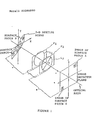
- FIG. 1 a perspective schematie diagram of the camera system of the present invention is shown viewing a three-dimensional spatial scene.
- Fig. 2 shows the details of the camera system of the preferred embodiment. It includes an optical system having a first lens l, 1 and a second lens l, 2 disposed along the common optical axis O.A. to facilitate changing the focal length f of Lhe lens system.
- the focal length f is a camera parameter.
- the lens system is characterized by a first principal plane P 1 and a second principal plane P 2 .
- An aperture stop A is placed immediately in front of the first lens L t .
- the diame-Ler of Lids aperture stop D is a camera parameter. This diameter is variable, but its value is always small enough so that the entrance pupil and the effective aperture of the camera system arc always determined by its value (and noL by some other stop inside the camera). Placing A s very close to lens L 1 at the front ensures that all objects iu the scene experience the same entrance pupil irrespective of their distance front the camera.
- the value of the focal length f of the lens system is changed by translating the lens L 2 back and forth along the optical axis.
- the other lens L 1 is preferably not moved au that it stays close to the aperture stop.
- the entrance pupil which is determined by the aperture stop should never be moved because such a movement causes the correspondence problem encountered in sterco-vision.
- Both lates L 1 and L 2 can be convex or one of them can be coneave. In either case the effective focal length / is determined from the well-known formula where f L 1 and f L 2 are the focal lengths of the two lenses L 1 and L 2 respectively, and r is the distance between the Lwo lenses. A similar formula can be used even if there are more than two lenses (see for example Chapters 5 aud 6 in the book titled Optics by Hecht and Zajec, Addison-Wesley Poblishers, 1974).
- the positions of the principal planes P 1 and P 2 and principal poinLs Q 1 and Q 2 of the lens system are determined using well-known methods in geometric opties, for example, as discussed in Chapter VII, Section 2 of the text Optics liy K. N. Ogle published by Charles C. Thomas, Springlield, Illiuois, in 1968.
- An an alternative method of changing Lhe effective focal length f by translating lens L 2 , one or both of the focal lengths f L1 , f L1 could be changed. This can be done by substituting one tens with another lens having a different focal length.
- the camera system also iucludes all image detector ID on which the actual image is formed and recorded.
- the distance between the second principal plane P 2 of Lhe lens system and the image detector lU is designated as s and constitutes a camera parameter.
- the value of the camera parameter s can be changed by translating the image detector ID back and forth along the optical axis.
- the value of s can also be changed by effectively moving Llie principal plane P 2 .
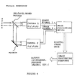
- Fig. 3 shows Llie camera system along wiLh an image acquisition device and au image processing computer
- the image acquisition device receives image signal from image detector and converts it to digital form. This digital image is them input to the image processing computer.
- This computer processes the input digital images Lo recover the distance of surface patches.
- the preferred embodiment optionally provides means for quantitatively measuring the value of the camera parameters, including changes in the camera parameter values effected by the means for varying the same.
- Fig. 15 shows a schematic block diagram of the Image processing computer. It con-sisLs of several modules that are usually found in Digital Signal Processing applications. An input device controller and an output device controller coordinate data transfer by the input and the output devices. A Central Processing UniL (CPU) assists in preprocessing operations. A Fast Fourier Transform (FFT) chip and Floating Point Arithmetic chip are also included to speed up processing. The main memory stores the input image data and also the intermediate results of processing operations at various stages.
- FFT Fast Fourier Transform
- the image processiug computer also contains two modules to determine Lhe distance of surface patches.
- the first module is a memory module containing a fast Random Access Memory (ItAM) or a Read Only Meiiiory (ROM) module which stores a table of preconputed values. This prestored table characterizes the camera system.
- the second module is a "look-up"/correlation module having special purpose VLSI hardware for fast table searching for a given set of computed values. This module performs eiLher a table look-up operation (which partially involves associative search) or computes a correlation measure and searches for its maximum.
- FIG. 4 An aliernaLive to the preferred embodiment is shown in Fig. 4 which can be used to acquire two images of a scene simultaneously.
- This embodiment is obtained by a minor modification to the preferred embodiment described above.
- this modified embodiment instead of using a single camera system which provides means for changing at least one (and possibly more) of the said camera parameters, multiple cameras are used where the camera parameter values of each individual cameras are dissimilar in at least one (and possibly more, and even all) camera parameter(s).
- this apparatus there is no necessity to provide for varying any of the camera parameters of the individual cameras.
- Each camera in used in acquiring one image corresponding to one set, of values of camera parameters.
- Each of the individual cameras view the scene through a common aperture with the aid of a beam-splitting arrangement. Except for this, other parts of the embodiment, such as the image acquisition device and image processing computer arc all similar to the preferred embodiment.
- Figure 5 shows two spherical coordinate systems (r,0, ⁇ ) and (r 1 ,0 1 , ⁇ 1 ).
- the first coordinate system (r,0, ⁇ ) is located at Lhe first principal point Q 1 and Lhe second coordinaLe system (r 1 ,0' , ⁇ 1 ) is located at the second principal point, Q 2 .
- the X and Y axis of both Llte coordinates lie in the principal planes and the Z axis coincides with the optical axis.
- a light ray incident on the firsL principal plane along the direction (0,0) emerges from Lhe second principal plane P 2 along the direction (d , ⁇ 1 ).
- the medium surrounding the optical system is the same every where (say air), and the optical system is circularyl symmetric about the optical axis.
- the present. invention can however be easily extended to a more general case where the medium surrounding the optical system is different at different positions and Llic optical system is not circularly symmetric.
- Image coordinale system contains an array of photosensitive sensor elements such as CCI) sensors arranged ou a two-dimensional surface. If (r d ,0, ⁇ ) is the set of points lying on the image detector surface, then the surface can be uniquely defined by the function
- the image or a scene formed by the optical system produces an image irradiance distribution on the image detector surface.
- This irradiance distribution call be expressed in Llie form uf a function as This function represents the image formed on the image detector.
- g(0, ⁇ ) can represent the image fur any arbitrary shape of the image detector surface.
- the image detector may he planar as in most CCI) cameras or iL may be curved as for example is the case with the retina of the human eye.
- the image detector surface is planar and is perpendicular to the optical axis, located at a distance s from the second principal plane. Therefore the equation of the image detector surface is It should be noted, however, that the present invention is not limited to any speciflc geometric shape or the image detector surface, such as, for example, the planar shape. The invention can be extended easily to arhitrary shapes of the image detector surface.
- the method of the present, invention could involve moving the image detector forward or back ward along the optical axis. Such a movement, of the image detector results iu a change in the magnification of the recorded image.
- a normalized Cartesian coordinate system (x,y) to specify points on the inmage detector plane. It is a hypothetical Cartesian coordinate system located at unit distance from the second principal plane. See Figure 0.
- the normalized Cartesian coordinates x,y of L h e point are NoLe that Lhe mapping between any direction specified by (0, ⁇ ) and the Cartesinan coordinates (x,y) defined as above is one to one, that is, given Lhe direction (0, ⁇ ) the normalized Cartesian corrdinates (x,y) arc uniquely determined and vice vcrsa.
- the inverse relation between them is given by Therefore, any image g(0, ⁇ ) ou the image detector can also be denoted equivalently by g(x,y).
- the focused image f (0, ⁇ ) is the total light energy per unit time incident on the entrance pupil of the camera system from Lhe object point located along Lhe direction (0, ⁇ ) in the sccue.
- This definition of the focused image is different from that found in the literature. Mere it is defined in terms of the energy incident on the entrance pupil rather than the brightness or radiance of object points in the scene. A clnlinitiou based on radiance of object points in the scene would make the focused image to be dependent on the distance of the objects in the scene. This is so because, although the light energy incident on the entrance pupil is proportional to the radiance of the object, it decreases inversely with the square of Lhe object distance from the camera system. The new definition decouples the effects of object radiance and its distance from the camera system, This new definition is necessary lo present a correct theory of the present invention.
- the definition of the focused image above although does not depend on the distance of objects, is still dependent on certain camera parameters. For example, it depends on the diameter of the camera aperture because, the indident light energy on the entrance pupil from an object point in the scene is proportional to Lhe solid angle subtended by the aperture at the object. point.
- the brighlness normalized focused image, ⁇ n (0, ⁇ ), is defined as where E is the total light energy incident on the entrance pupil corresponding to ⁇ (x,y). IL is computed as We will also refer to the 'brightness normalized focused image' as simply the 'normalized focused image'.
- the image detector contains an array of photo sensitive sensor elements (for example CCD sensors).
- the inverse function c 1 (b) is initially determined through a calibration procedure.
- the camera manufacturer may provide specilications which relate the response of the image detector to the actual image irradiance. For an observed image g(0, ⁇ ), the operaLion of correcting for the non-linear response of the sensor elements is given by where the symbol ⁇ means 'becomes'.
- the light incident on the entrance pupil is usually attenuated by a small factor by the optical system due to absorption or vignetting effect.
- the attenuation l usually changes with direction (0, ⁇ ). Therefore the attenuation can be characterized in the form of a transmission function l(0, ⁇ ). If g(0, ⁇ ) is the image formed on the image detector, then the effect of non-uniform light transmission is corrected by the operation
- An image g(0, ⁇ ) (or g(x,y)) on which the operaLions of sensor response correction, and non-uniform transmission correction have been performed is called the observed image or the scene.
- the total ligltL energy incident from the scene on Lo the entrance pupil could change due to change in the camera parameters. For example, increase in the diameter or the camera aperture could increases the total incident energy.
- the image g(0, ⁇ ) is normalized by the total light energy incident on the entrance pupil.
- the total incident light energy E is computed as
- the brightness normalized observed image g n (0, ⁇ ) is defined as
- the point spread function (PSF), expressed as h (0, ⁇ ), or the camera system is defined as the observed image (in the sense defined above) produced by a point light. source whose brightness is such that the total light energy per uniL time incident on the entrance ppil from the point light source is one unit.
- the point spread function h(0, ⁇ ) corresponding to a point light sourcc P at position (r 0 ,0 0 , ⁇ 0 ) depends on the following parameters: (i) the position of the image detector s, (ii) the focal length f of Lhe optical system, (iii) the diameter or the aperture D, (iv) the wave length ⁇ (or the spectral content) of light entering the optical system, and (v) the position (r 0 ,0 0 , ⁇ 0 ) of the light source P. It can also depend on other parameters such as, for example, the degree of coherence of the light, incident on the entrance pupil, but these other parameters are considered to remain the same for different images being recorded. However, the present invention can be easily extended to the case where one or more of these other parameters change from one recorded image to another recorded image.
- the point spread function h( ⁇ , ⁇ ) however does not depend on the angle ⁇ 0 .
- the optical system is circularly symmetric around the optical axis. Therefore ⁇ 0 will be dropped from further consideration.
- Lhe method of the presentinvention can be extended to the ease where the point spread function does depend on ⁇ 0 . It is nut. limited to circularly symmetric optical systems.
- the point spread function depends on the angle ⁇ 0 with respect to the optical axis because of Lhe change in lensaberrations. However, within small intervals of the angle ⁇ 0 the aberrations can be Laken Lo remain approximately the same. Therefore the total field of view of the camera system is divided into many small intervals of ⁇ 0 within which the aberrations arc nearly constant. These intervals are of the order of a few degrees.
- the actual aberrations in each interval call be predetermined Lhrough calculations or means-urement.
- the observed image is correspondingly divided into smaller subimages and analyzed separately in each interval. This topic is discussed further later, but for the present Lhe subimage Lo be processed is considered Lo lie in one of the intervals of ⁇ 0 inside which the lens aberrations are a constant.
- the set of parameters on which the point spread function h( ⁇ , ⁇ ) depends in the preferred embodiment are: (i) position of the image detector s, (ii) focal length f , (iii) aperture diameter D , (iv) wave length of light ⁇ , and (v) distance of object r 0 .
- independent, parameters are cousidered to be disLincL independent variables of the point spread function h.
- the independent parameters are not combined to yield an intermediate blur parameter (e.g. o) and Lake iL as the independent variable or the function h. From the definition or the point spread function, it follows that lit particular, the above relation holds good for all possible values of the vector e a and distance r 0 .
- the spread ⁇ of the point spread function can be defined its the standard deviation of the distribution of the point spread function, i.e.
- the PSF h(x,y ; e a ,r 0 ) has significant values only in a very small region around its center or mass. This region extends up to a radius of about two or three times the spread ⁇ . Outside this region the I"Sl" has values very close to zero and hence is insignificant.
- An object in the scene located at position (r 0 , ⁇ 0 , ⁇ 0 ) produces an image ou the image detector. See Figure 7.
- the position (r 0 , ⁇ 0 , ⁇ 0 ) here in fact represents the position uf the center point (say the center of mass) of a surface patch on Llte object.
- the direction ( ⁇ , ⁇ ) of every point oii the surface patch is trivially det-ertnincd exactly because the direction of a point in the scene is the same as the direction or its image on the image detector.
- the distance r 0 of the surface patch from the camera system remains Lo be determined.
- the size of the surface patch is taken to be such that Lhe point spread function is nearly the same for all points on the surface patch.
- the surface pateh in the scene that is of interest is Laken to be such that iL subtends a solid angle aL the lirst principal point Q 1 having a square cross seetion parallel Lu the image defector planc.
- Lhis solid angle as the field of vicio corrcsponding to the surface patch.
- the center of this fiekl of view is given by ( ⁇ 0 , ⁇ 0 ) and we will designate the corners of Lite lield of view by the directions ( ⁇ 1 , ⁇ 1 ), ( ⁇ 2 , ⁇ 2 ), ( ⁇ 3 , ⁇ 3 )' and ( ⁇ 1 , ⁇ 1 ), in counter-elock wise direction.
- the center and the foar corners of Lhe lield uf view corresponding to the surface patch can be specified in teh normalized Cartesian coordinates by the points (x 0 ,y 0 ), (x 1 ,y 1 ), (x 2 ,y 2 ), (x 3 ,y 3 ), and (x 1 ,Y 1 ), respectively.
- the four corner points (x i ,y i ) for i 1,2,3,4, specify a square region in the normalized Cartesian coordinate space.
- the image of the surface pateh recorded by the camera system is lirst preprocessed for scnsor response correction (according Lo equation (10)) and then non-uniform light transmission (according to cquation (11)).
- the resulting image 9 (0, ⁇ ) is referred to as the obscrved image of the surface palch.
- the camera system essentially acLs as a linear shift-invariant system.
- the primary goal of the discnssion in the tast few pages has been to lay a theoretical framework in which the camera system can be modeled as a linear shift-invariant system. It is to this end that the steps uf sensor response correction and non-uniform tranmnission correction have been introduced. For some camera aystems, depending on their design and characteristirs, some of these preprocessing steps may not.
- Lhe observed image g (0, ⁇ ) of the surface patch is in fact the result of convolving the corresponding focused image f (0, ⁇ ) with the point spread function h (0, ⁇ ; c a ,r 0 ) of the canera system.
- This relation is exprcssed as where * denotes teh convolution operation.
- This same relation holds for the brightness normalized images 9a (0, ⁇ ) anti f" (0, ⁇ ), that is Note that the above relation is derived from the fad that The above equation is a consequence of the conservation or ligli energy (see equation J 6).
- Relation (20) can be expressed equivalently in the normalized Cartesian coordinate space as Equation (22) above relates a suitably preprocossed recorded image g a (x,y) of a surface pateh with the normalized focused image f a (x,y) of the same surfacc pateh in terms of the camera parameters and the distance of the surface pateh.
- the camera paramelers and the distance of the surface pateh together determine the point spread funetion h(x,y ; e a ,r 0 ).
- Equation (22) Taking the Fourier transform of equation (22) gives the following relation: where w,v are teh spatial frequencies, Gn(w,v) is the courier transform of the brightness normalized observed image g a (x,y), II(W,y; c a ,r 0 ,) is the Fourier transform of the PSF h(x,y; ca,r0), and Fa(w,y) is the Fourier transform of the brightness normalized focused image f n (x,y). II(w,v; c a ,r 0 ) is called the Optical Trausfer Funetion or OTF of the camera system.
- a lirst observed image 9 1 (x,y) of the surface pateh is obtained with the camera parameters set to the lirst scL or values denoted by c a ( where A second observed image g 2 (x,y) of the surface patch is obtained with the camera parameters set to the sccond set of values denoted by ca 2 where In the two camera settings ca 1 and ca 2 , at least one of the camera parameters s,f d, ⁇ , must be different, i.e. ea1 ⁇ ca 2 (otherwise the two observed images g 1 (x,y) and 9 2 (x,y) will be the same.).
- ga 1 (x,y) and ga 2 (x,y) be the brightness normalized images corresponding Lo the observed imagcs g 1 (x,y) and g 2 (x,y) respectively.
- the values or gn1(x,y) and g n2 (x,y) will be known at a diserete array of ponts corresponding to the positions of the photo elements on the image detector.
- the diserete array corresponding to g n1 (x,y) will be lager than the discrete array corresponding to g n2 (x,y)
- the discreLe values of (x,y) aL which g n1 (x,y) is kuuwn will lrc denser (or more closely spaced) than the diseate values of (x,y) at which g n2 (x,y) is known.
- magnification normalization takes care of changes in magnifration of the images and therefore is called magnification normalization.
- G n1 (w,v) G n2 (w,v) are the Fourier transforms corresponding Lu the images g n1 (x,y), g n2 (x,y) respectively (after magnification normalization), then we can derive the following relation from equation (23):
- the left hand side is the ratio of the Fourier transforms of two preprocessed images recorded with different camera settings.
- the right hand side is the raLio of the corresponding Optical Transfer Functions. This equation is independent of the normalized focused image (indeed, the Lerm corresponding to the normalized focused image cancels out while deriving this equation).
- the left hand side can be computed from Lhe recorded images. Given all the required camera paraatmeters, an analylic expression can be derived for the right hand side. This results in all equation where the distance r 0 is the only unknown. Solving this equation gives the distance r 0 of the surface patch.
- Gaussian model for the PSF is however an approximation Lo the netual form of the PSF.
- the present invention deats with an arbitrary PSF of a camera sysLem with no restriction on its form.
- the second method of solving equation (26) is a table look-up method. This method is very convenient front a practical point of view.
- the function on the right hand side of equation (26) is tabulated as small discrete intervals of r 0 . See Figure 8.
- the table entries arc in general complex valued and therefore cuu be expressed in polar form as where It is often sufficient to cither tabulate only the ⁇ ,(w,v;r 0 ) as for example is the case when the PSF is a Gaussian or a Cylindrical function, or tabulate unly the ⁇ ,( ⁇ , ⁇ ;r 0 ) as fur example is the ease when the PSF is a Cylindrical function.
- the OTFs are always real valued every where (this follows from the properties of the Fourier transform).
- the phase ⁇ is always either 0 or n but ⁇ , c:m be any positive real valuc. Therefore ⁇ , contains almost all the required information in this case.
- ⁇ atone contains suffieient information to delermine the distance r 0 , it can be computed as the square root of the power spectrum. This is aii important point to note because power spectrum of an image can be computed very fast by optical means.
- the Lahle T s (w,v,r 0 ) is stored in a four dimensional array (see Figure 8) of size M ⁇ N ⁇ U ⁇ 2 where the first dimension corresponds to M distinct values of w, the second dimension Lo N distinet values of v, and Lhe third dimension to U distinct values of r 0 .
- ⁇ s is stored as the first entry and the phase ⁇ , is stored as the second entry.
- Equation (31) is not enforced strictly in solving for r 0 for two reasons.
- the table T,(w,v;r 0 ) is stored at diserete values of r o , each entry in Lhe table acLually corresponds to a small interval around the actual r 0 for which the table cntry has been stored.
- the second reason is noise. Therefore, from each solution set R 0 (w,v, ⁇ c , ⁇ c ), at least one r 0 that is most consistent with other solution sets is chosen.
- the initial 2U comparison operations during the search can be reduced if the table is extended by one entry in the fourth dimension Lo store r 0 and sorL the entries neeord-ing to ⁇ s and ⁇ 2 along Lhe third dimension instead of r 0 .
- the sorted lisL can then be searched in O(log U) operations using one of the well-known searching algorithus (e.g. binary search).
- a correlation method can he used which is essentially an exhaustive search of Lhe table T s ( ⁇ , ⁇ ,r 0 ) with respect to r 0 for a most, consistent solution.
- the search is carried ouL by computing a correlation measure between computed values T e ( ⁇ , ⁇ ) from the observed images, and the prestored values of T s ( ⁇ ; r 0 ) in Lhe table for each possible value of r 0 .
- the value of r 0 that results in the highest correlation can be taken as the distance of the object.
- An example of a correlation measure is the correlation coefficient delined as where the superscript.
- a step by step desription of the operation to be performed to fined ilic distance of a surface patch using the preferred embodiment of the camera system is given herein.
- the camera In order to fined the distance of a surface patch, the camera in set to a first camera setting; at whish a first image of the scene is recorded. The camera is then set to is second camera setting where c n1 ⁇ c n2 , and a second image or Lhe seene is recorded.
- Extrart Llw image of the surface patch from the first recorded image for processing This exteacted image has the same brightest values as the first recorded image inside the sequare field of view selected and in represented by y 1 ( ⁇ , ⁇ ). The value outside the selected aquare field of view is zero.
- Sensor response correction can he applied if necessary as in equation (10), and non- unifurm transmission correction can be applied if necessary as set forth in equation (11).
- Maginfication correction correction can also be applied. If s 1 >s 2 then the singal is interpolated and y 1 ( ⁇ , ⁇ ) in resampled at the same set of descrete points where y 2 ( ⁇ , ⁇ ) is known.
- Additional preprocessing steps can be carried out, if ncessary, to model the camera as a linear shift-invariant system.
- the image is expresed as y 1 (x,y) ill a mormalized Cartesian coordinate system according Lu equation (b).
- Image-overlap effect at the bord crs uf the image y 1 (x,y) can be reduced by multiplying iL by a suitable center-weighted mask ⁇ (x,y) (e.g. a two-dimensional Cassian), i.e.
- the total (ur mean) brightness of y 1 (x,y) and y 2 (x,y) is made Lu be the same, such as unity as in capuation (13).
- the image of the surface patch is extrated from the second recorded image fur pro-eessing.
- the extracted image has the same brightness values as the second recorded iamge inside the selected square field of view, and everywhere outside the square field of view the brightness value is zero.
- This second image in represented as y 2 ( ⁇ , ⁇ ).
- the second recorded iamge is processed as the first image fur sensor response correction, correction for non-unifrom transmission, magnification correction, brightness non-malization, other preprocessing steps, and image overlap reduction,
- the resulting image is denoted by y n2 (x,y)
- a threshold parameter function ⁇ ( ⁇ i , ⁇ j ) can be speecified based on image noise characteristic of the camera system. Then, if
- the Optial Transfer Function II is derived from a theory of image formation (e.g. paraxial geometric optics Llicory, or wave optics theory).
- the values of ⁇ i , ⁇ j ,e a1, c a2 arc substitued in the above equation, and the equatin can be solved to obtain all possible solutions for the distance r 0 .
- au expliciL analytic expression can be derived for r 0 , then this expression is used to compute r 0 . Otherwise, a numerical iterative technique is used. ln either case, if there arc multiple solutions, then spurious solutions are diminated by requiring all the solutions Lo be consistent fur all possible spatial frenquencies ( ⁇ i , ⁇ j ).
- Use ( ⁇ i , ⁇ j , ⁇ cij , ⁇ cij ) Lo index into a prestored table in computer memory to find one set of aolution R 0 ( ⁇ i , ⁇ j , ⁇ cij , ⁇ cij ) for the distance r o .
- a third method compute the correlation codllicicut c i (r 0 ) between the computed r c ( ⁇ i , ⁇ j ) and a function r s ( ⁇ i , ⁇ j ; r u ) prestored in computer memory for all possible distances r 0 .
- Optical Transfer Function II of the camera system can be expressed.
- This Optical Transfer Function can be expressed iu terurs or the camera parameters c u , the distance r 0 of a surface patch, and the Fourier spatial frequencies ( ⁇ , ⁇ ).
- a suitable set of camera settings c a1 ,c a2 are chosen and the discrele values of ( ⁇ , ⁇ ,r 0 ) at which the option) transfer function needs to be computed can be determined.
- the valuc or the optical transfer function II( ⁇ , ⁇ ; r 0 ) can be computed at discrete values of ( ⁇ , ⁇ ; r 0 ) using the expression derived prevtously.
- the computed values call be stored in computer memory and used in determining the improved focus image of a surface patch.
- Lu precompute a table for determining the distance of a surface patch given two images of it taken with different camera settings c a1 and c a2 , first computed the optical transfer functions of the camera for camera settings c a1 and c a2 at desired discrete values of ( ⁇ , ⁇ ; r 0 ).
- the ratio or these optical transfer functions gives the requiredtable valtus which enn bc computed in the following form: and stored in computer memory.
- the Lible computed is complex valued.
- Each cutry can also be stored in the magnitude and phase form according to equations (30a,30b).
- the optient system is eircularly symmetric (this is largely true of most practical camera systems).
- the point spread function is cylindrical or "pill-box" given by where R is the radius of the blur circle.
- Equation (32) Since the point spread function in equation (32) is circularly symmetric, Lhe optical transfer function is also circularly symmetric. Therefore a single spatial frequency parameter p in the optical transfer function can be used where The Fourier transform of equation (32) is Lhe optical transfer function given by where J 1 is the first order Bessel function. This equation explicitly represents the depen-deuce or the optical transfer function on the camera paratneters and the objccL distance.
- the second method of obtaining the table T s (w,v,r 0 ) is through experiments.
- the experimental method is convenient, if an analytic expression for II(w,v,c n ,r 0 ) is noL available, or iL is difficult to compute, or it is diffcult to measure c a 1 , c a 2 of the camera system accurately.
- the observed image of the camera system y 1 (x,y) fur camera setting c a 1 and y 2 (x,y) for camera setting c a 2 are recorded for each possible value of r o at small discrete intervals.
- SeL the camera Lo a first camera setting c a 1 and record a first image of the scene as previously explained. Similarly, set the camera to a second camera setting c a 2 and record a second image.
- Extract a subimage g 1 (0, ⁇ ) from the first recorded image which conLains the image of Lhe picture pattern and surrounded by a wide dark band corresponding to the image of Lhe board. Images of no other objects should be present in this subimage. This ensures that almost all of the light distribution produced by Lhe attached picture is recorded in the extracted subimage. Furthermore, border effects arc avoided as the intensity remains constant at the border. Repeat this step for the second recorded image and extract the subimage g 2 (0, ⁇ ).
- equation (28) If the table is obtained experinuentally using equation (10), then the actual camera parameters c u1 and c u2 can be obtained using equation (28). This of course requires knowledge of an analytic expression fur the riglil hand side of equation (28). For each table entry corresponding to a particular value of ( ⁇ , ⁇ ,r 0 ), one constraint is obtained on the camera parameters c a1 , c a2 given by equation (28). Writing this constraint for all table entries, a a large overdetermined system of equations is obtained. Now the problem is to solve these equations to obtain the camera parameters c a1 , c a2 .
- this is the classical parameter estimation problem which can be solved by one of the well-known techniques in applied mathematics, for example the least-squares error minimization technique.
- this technique gives a method for determining n unknown parameters of a camera system using aL least n + l images or a surface patch, each image acquired with diffcrcnt camera settings.
- the size or the interval uf 1/u in terms of the camera parameters.
- the size U or the table along the u dimension is Therefore the table size is D/p.
- the pixc:l size p itself is determined by the sensor technology and Llie diffraction limited resolution of the optical system. According Lu the widely used Rayleigh Criterion, the angular separation of two points that are barely resolved by our lens system is Not much is gained by making the angular aize p/f of the pixel smaller than this. Therefore,
- p is the distance between two sensor elements, it represents the spatial sampling period of the image signal.
- the sampling period is p/s where s is the distance of the image detector from the second principal plaue. If the sampled image is a discrete array of size M ⁇ N elements, then the Discrete Fourier Transform (DFT) of the magnification normalized image contains M ⁇ N distinct spatial frequencies ( ⁇ , ⁇ ) given by Therefore, the maximum table size is lii general, depending on the specific application, the table size could be smaller.
- DFT Discrete Fourier Transform
- a method for linding the distance of a surface patch of an object from a camera sys-them has been described above in detail.
- a similar method is used for the rapid auLo-forcusing of a camera system.
- Lhc focusing formula such as Lhe leus equation (34) can be used to determine camera parameter values ⁇ s,f ⁇ which bring the surface patch into focus.
- the distance (and possibly the field of view in which the surface paLch lies) is used Lo index into a prestored table in computer memory which provides desired camera parameter values ⁇ s,f ⁇ for bringing the surface patch into focus.
- the camera parameters are subsequently achieved by moving Llte camera elements to obtained focus parameters ⁇ s,f ⁇ .
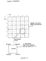
- Recored Lwo images of Lhe scene for two different camera settings as in llie method of determining the distance of a surface patch Divide the field of view of the camera into many smaller subfileds as in Fig. 10 and Fig. 11. The size of these sublields are chosen such that within each sublield optical aberations remain nearly constant. For the con-venience of implementation, make the subfield-of-views have a square cross section paral-le Lo the image detector.
- Equation (53) In order to obtain the improved focus image according to equation (53), we need Lo known the OTF H(w,v; e u ,r 0 ) of the camera system. Determination of the OTF is similar to the determination of the table T s (w,v,r 0 ) in the method of determining distance described earlier. There are two methods of determining the OTF, one is from a theoret-ical model of the camera system, and the other is through experiments. In the first method, the theoretical model of the camera sysLcm is used to derive an analytic expression for the OTF in terms of the camera parameters and the disLancc of the object. For exmaple, equation (37) is derived from the paraxial geometric opties theory.
- an image formation theory e.g., paraxial geometric optics or classical wave optics
- An expression is then derived for the OTF, II, of the camera system in Lerms of the camera parameters c a , the distance r o of a surface patch, and the Fourier spatial frequencies (w,v).
- a suitable set of camera settings c a 1 ,c a 2 must be chosen. Then the discrete values of (w,v;r 0 ) at which the OTF needs to be computed are determined.
- the value of the OTF H(w,v;r 0 ) at discrete values or (w,v;r 0 ) are determined for a given camera settingm, e.g., c a . These values are stored in computer memory for use in determining the improved focus image of a surface patch.
- the theoretical method of determining OTF required the accurate knowledge or the camera parameters c a .
- An alternative to the theoretical approach is the experimental calibration of the camera system.
- all object having a known focused image f(x,y) is imaged for all possible distances r 0 of the object from the camera system.
- the camera parameter setting c u remains unchanged.
- the actual values of the camera parameters need not be known.
- the observed image g(x,y;r 0 ) is recorded.
- the OTF is then computed from The OTF is prestored in computer memory in a three-dimensional array indexed by (w,v,r 0 ). This table is similar to the table T s (w,v,r 0 ) used in the method of finding distance or objects.
- a subinage g l ( ⁇ , ⁇ ) is extracted from the IirsL recorded image which contains the image of the picture pattern and surrounded by a wide dark band corresponding to the image of the flat board bchind. lmages uf no other objects should be present ill this subimage. This ensures that abnost all of the light distribution produced hy the pasted pieture is pecorded in the extracted aubinage. Further, iL avoids border dlfects as the intensity remains constant at. the border. Repeat the above fur the second recorded image and extract the subimage g 2 (0, ⁇ ).
- the images g 1 (0, ⁇ ) and g 2 (0, ⁇ ) are aormalized and Lhe noise minimized as described hereinabove for application Lo values entered in the prestored table.
- the focused image ⁇ (x,y) or the picture pasted ou the flat board is found by some means (e.g. by actually focusing Lhe camera on the picture aud recording iL, or separately (ligiliziiig the pieture pattern).
- the focused image ⁇ (x,y) is normalized fur brightmess, magnilication, etc. Lu obtain ⁇ n (x,y).
- the Fourier trausform F a ( ⁇ i ,v j ) of ⁇ n (x,y) is computed. If
- Another method or obtaining improved focus image from a single blurred image involves human intervention. If a blurred image taken with Llw camera parameters set to c a is given, and the OTF II( ⁇ , ⁇ ;c a ,r 0 ) is known either in Lhe form of an analytic expression or in the form of a prestored table, then the blurred image is inverse liltered wil.h respect Lo this OTF for each possible value of distunce r 0 . As a result, a sequence of images are obtained which are candidates for the focused image. These images are then presented to a human subject, who can select the "focused image" from the image sequence.
- This method is useful for blurred images containing objects familiar to hutnans, for example faces of people, c:ars, houses, etc.
- the human subject need to be familiar with only the generic object in the image, not nceessarily the specific instance of the object.
- iL is anly necessary to know that a given blurred image is the face of a person, and it. is not required to have ectually seen that peraon before.
- the above method for detormining one unknown parameter can be extended to obtain a method Lo determine more than one unknown. In this case more than two images are needed. In general, if n unknowns are involved then u 1 1 images are required.
- three pie-tures g 1 (x,y), g 2 (x,y) and g 3 (x,y) arc taken with camera settings c a1 , c a2 , and c a3 respectively where
- Equations (57),(58) are solved simultancously to obtain the two unknowns ⁇ , r 0 .
- a method is described here to estimate the uncertainty in the determination of disLance r 0 in terms of the uncertainty in the measurement of Lhe imago signal and the camera parameters.
- the image-overlap problem involves dividing the original observed images into smaller subimages and processing pairs of subimages separately. Dividing a large image iuto many smaller subimages introduces some errors due to horder effects.
- An image region cannot be analyzed in isolation because, due to blurring caused by the finite spread of the point-spread-function, the image irradiance distribution produced by one surface pateh on the image detector overlaps with the image irradiance distribution produced by adjacent patches. This overlap could be significant, at the borders of Lhe itnage region. This is called the image overlap problem.
- the image overlap problem can be completely avoided through selective illumination of the scene.
- the scene can be illuminaled by square bright patches separated by wide dark bands with no illumination.
- Lhe boundaries of Lhe subimages Lo be analyzed separately can be chosen to be in the middle of the dark bands. Border effects are then avoided because the image intensily is zero at and near the borders.
- the image overlap problem may he reduced as follows. The image intensity is first multiplied by a suitable center weighted (e.g. a Gaussian) mask centered at the region of interest. The resulting weighted image is then used fur further processing. Because the weights are higher at the center than at the periphery, Lhis scheme gives an estimate or Die unknown quantity which approximately corresponds to the center of the field of view.
- a suitable center weighted e.g. a Gaussian
- Plain objects Objects like machine parts, wall, door, road, etc. are often "plain” or "textureless", i.e. their surfaces arc smooth and have no rellectance variation. Therefore Lhey appear as objedcts with coastant brightness under uniform illumination. They lack spatial frequency content. In this case, if the illumination of the scene is under control (as in indoor scenes), then spatial frequency content can be artificially introduced by projecting an arbitrary light pattern (e.g. a random doL or "texture" pattern) onLo the surface of objects. See Figure 12. Then the method of the present invention can he applied to determine the distance of the object.
- an arbitrary light pattern e.g. a random doL or "texture" pattern
- Deconvolution The focused image of a surface patch can 1m obtained by 'dividing Lhe Fourier transform of the observed image by the corresponding optical transfer Funetion.' This operation, called deconvolution is diffienlt to implement in practice due to noise and the presence of singularities.
- Some type of constrained deconvolution should be applied based on some a priori knowledge about the noise characteristics and the image. Signal processing area abounds with literature on this topic. Therefore, Lhis problem is nut elaborated on here, but iL is understood that some sort of constrained deconvolution is meant when we sty deconvolution.
- the method here is based on a Fourier domain analysis of the images. It is possible to do a corresponding analysis iu the spatial or other suitable domain.
- the Fourier domain has been chosen for its simplicity. Analyses in other domains that are analogous Lo our Fourier domain analysis are considered to be within the scope of the present invnetion.
- Panasonic WV-CD 50 is a CCD camera with focal length 16mm, aperture diameter 10mm, and pixel size 0.013 ⁇ 0.017 mm 2 .
- the table T(p,u) can be easily compated using a computer. The following data is a typical example for such computation.
- the computed table values can be thresholded, say at ⁇ 1.5, and shifted and scaled to fie in the range 0 and 255.
- the resulting table can be displayed as a gray-level image.
- a grey-level image thus computed for this numerical example is shown in Fig. 16. Because the two optical transfer functions cross zero aL different values of p and u -1 , nearly periodic discontinuities (jumps from negative inlinity to positive infinity) are found. These discontinuities represent boundaries of regions in the ⁇ (p,u) space as sudden change in phase from 0 Lo ⁇ . Within each region the phase remins the same (i.e. either U or ? r), but changes aL the boundaries of the region from either 0 to ⁇ or from ⁇ Lo 0.
- the present invention also contemplates a general theory that is applicable to all linear shift-invariant systems, i.e., systems that perform convolution operation.
- This theory is essentially a generalization of the method for finding distance of surface patches described earlier, This theory is believed to be useful for a wide variety of instruments that can be modeled as linear shift-invariant systents.
- a camera system is just one example of an instrument, where the application of this theory has been presented in complete detail.
- the theory presented here deals with a general method for (i) estimating one or more unknown physical parameters of Lhe system that characterize the system, and (ii) to obtain the original input signal of the system from the output or Lhc system.
- Equation (104) can be expressed as where represents the Fourier frequencies corresponding to x, and G(w), II(w;e), F(w) are respectively the Fourier transforms of g(x), h(x;e), and f(x).
- iL is ofLen the case that, in addition Lo the input sigual f(x), one or more of Llw system parameters e i are not known. Therefore the STF cannol be determinad, and consequently the inverse filtering operation in equation (107) cannnot be carried out Lo recover the input signal. A method is described here for determining these unknown system parameters. Having done Lhis, the input signal can be recovered through inverse filtering (using equation (107)).
- Equation (105) can be expressed as Let the system he such that one or more of the components of c n can be changed by known amounts. We will denote Lhc different values of c n by c a 1 , c a2 , c a3 , etc. The output of the system is then recorded for q ⁇
- equation (113) be satistied for all possible frequencies w that arc significant in C,(w) and G i (w) This will, in general, givc a unique solution fur c b . Further, this additional condition can be used to achieve numerical stability !it practical applications. Therefore repeat equation (113) is repeated with this additional condition. for all ⁇ such that
- the output of the system should be recorded for q I-I different configurations given in expression (112) ( Figure 11a).
- q+1 separate lincar systems each haviiig one conliguration in expression (112) (see Figure 14).
- the same input signal ⁇ (x) Is fml to all the q+1 systems, their outputs are recorded, and processed Lu obtain c b .
- C6 can change provided that the amount of change is known.
- q+1 configurations corresponding Lu c b can be where c b1 , c b2 ,..., c bq+1 , are all known. to this case again, one can write q equations corresponding to equation (114) in exactly q unknowns. They can be solved Lo obtain c b .
- This table is then sorted with respect to ⁇ and T i and stored i ll a new table c b (w,T i ).
- This new table could be multiple-valued Given wand T i where T i is computed from the recorded signal as the set of possible solutions for c b is obtained by indexing into the table c b (w,T i ) luter-secting such sets over all w and i gives the solution for c b , i.e. Efficient computational methods for set intersections can be used to lind the unique solution.
- the table size for storing the table depends on the capabilities of the aclual physical system, the accuracy with which it can be calibrated, the accuracy with which the signal g(x) and the system parameters c ui can be measured, and the accuracy of the analytical expression fur the STF II(w;c).
- the system of equations (114) constitutes q equations in exacLly q unknowns. Therefore, iL is just exactly constrained. It requires only q+1 recorded outputs. However, the accuracy of the results can be improved by using more ouput recordings than just the required minimun. For example, if q+2 recordings are used, then two estimates of the unknown cy can be made, the lirsL eslimale using the first q-t i output recordings, and the second eslimale from the last q 11 output recordings. A. weighted average of separate estimates of the unknown c k then gives a more robust estimate than the individual estimates.
- results can be derived for this general theory that have direcL aualogy to the results derived carlier for the special theory of camera systems.
- an equation for determining the uncortainty in tile solution for the unknown system parameters in terms of the uncertainty in the signal measurement and the known system paratuetern can be derived. All such results arc within the scope of the present invention as delined by the claims.
- the method has been generalized Lu determine the value of one or more camera parameters of the camera system.
- the method has been further generalized Lo input signal restoration and system parameter estimation in any linear shift-invariant system.
- This general Llrcury is applicable Lo a wide range of measuring instruments which can be modeled as linear shift-invariant systems.
- An electronic camera system is only onn example of the large class of instruments where tlie application of this general theory has been presented in detail.
- the present invention was mainly conceived in Llte context of machine vision ap p l i-cations such as robot vision, autonomous vehicle navigation, a means for finding approx-imate distance of objects as parL of a stereo vision system, etc.
- machine vision ap p l i-cations
- autonomous vehicle navigation a means for finding approx-imate distance of objects as parL of a stereo vision system
- this invention can be used after minor moditications.
- it in useful in television microscopy in obtaining improved focus images of three-dimensional specimens, and in commercial television broadeasting of images where objects in both the foreground and the background arc in focus.
- Il ia also useful in commercial video recorders for rapid autofocusing of desired objects in the scene.
- Another application is a completely electronie camera where laking a picture involves storing the image signal directly on a magnetic disk for Lwo or more camera settings, and then processing this image signal on a computer in conjunetion with camera characteristies to obtain pictures with desired depth-of-field.
Landscapes
- Engineering & Computer Science (AREA)
- Multimedia (AREA)
- Physics & Mathematics (AREA)
- Signal Processing (AREA)
- General Physics & Mathematics (AREA)
- Radar, Positioning & Navigation (AREA)
- Remote Sensing (AREA)
- Electromagnetism (AREA)
- Automatic Focus Adjustment (AREA)
- Focusing (AREA)
- Measurement Of Optical Distance (AREA)
- Studio Devices (AREA)
Applications Claiming Priority (4)
| Application Number | Priority Date | Filing Date | Title |
|---|---|---|---|
| US37399689A | 1989-06-29 | 1989-06-29 | |
| US373996 | 1990-06-15 | ||
| US07/537,117 US5193124A (en) | 1989-06-29 | 1990-06-15 | Computational methods and electronic camera apparatus for determining distance of objects, rapid autofocusing, and obtaining improved focus images |
| US537117 | 1990-06-15 |
Publications (3)
| Publication Number | Publication Date |
|---|---|
| EP0408224A2 true EP0408224A2 (de) | 1991-01-16 |
| EP0408224A3 EP0408224A3 (en) | 1991-09-18 |
| EP0408224B1 EP0408224B1 (de) | 1995-09-06 |
Family
ID=27006393
Family Applications (1)
| Application Number | Title | Priority Date | Filing Date |
|---|---|---|---|
| EP90307146A Expired - Lifetime EP0408224B1 (de) | 1989-06-29 | 1990-06-29 | Rechnerische Methoden und elektronische Kameravorrichtung zur Bestimmung der Entfernung von Objekten, zum schnellen Autofokussieren und um eine verbesserte Bildschärfe zu erreichen |
Country Status (4)
| Country | Link |
|---|---|
| EP (1) | EP0408224B1 (de) |
| JP (1) | JP3305314B2 (de) |
| AT (1) | ATE127582T1 (de) |
| DE (1) | DE69022143T2 (de) |
Cited By (12)
| Publication number | Priority date | Publication date | Assignee | Title |
|---|---|---|---|---|
| FR2702056A1 (fr) * | 1993-02-23 | 1994-09-02 | Centre Nat Rech Scient | Appareil et objectif de prise de vues en stéréovision axiale. |
| WO1999031542A1 (en) * | 1997-12-18 | 1999-06-24 | Cellavision Ab | Image content autofocus for microscopy using a noise-insensitive focus filter |
| GB2367440A (en) * | 2000-08-04 | 2002-04-03 | Mark David Cahill | Linear image reconstruction |
| EP1129383A4 (de) * | 1998-11-09 | 2006-04-26 | Univ Washington | Verfahren und vorrichtung zur bestimmung optischer entfernungen |
| US20120078510A1 (en) * | 2010-09-24 | 2012-03-29 | Honeywell International Inc. | Camera and inertial measurement unit integration with navigation data feedback for feature tracking |
| CN102679963A (zh) * | 2012-05-15 | 2012-09-19 | 中国科学院西安光学精密机械研究所 | 航天相机真空中焦面预置方法及装置 |
| AU2011224051B2 (en) * | 2011-09-14 | 2014-05-01 | Canon Kabushiki Kaisha | Determining a depth map from images of a scene |
| CN109648210A (zh) * | 2019-02-14 | 2019-04-19 | 北京志恒达科技有限公司 | 激光灼刻装置及系统 |
| CN112596324A (zh) * | 2020-12-21 | 2021-04-02 | 北京航空航天大学 | 一种基于液体变焦相机的智能机器人视觉识别系统 |
| CN113624358A (zh) * | 2021-07-14 | 2021-11-09 | 中国电子科技集团公司第十三研究所 | 用于光热反射显微热成像的三维位移补偿方法及控制装置 |
| CN116709614A (zh) * | 2023-08-02 | 2023-09-05 | 深圳爱图仕创新科技股份有限公司 | 灯光控制方法、装置、计算机设备及计算机可读存储介质 |
| CN119027350A (zh) * | 2024-08-19 | 2024-11-26 | 中国计量科学研究院 | 一种基于高频聚焦探头声场校准的超声显微图像恢复方法 |
Families Citing this family (10)
| Publication number | Priority date | Publication date | Assignee | Title |
|---|---|---|---|---|
| JP2006003803A (ja) * | 2004-06-21 | 2006-01-05 | Olympus Corp | 合焦情報取得装置及び合焦情報取得方法 |
| JP2006324985A (ja) * | 2005-05-19 | 2006-11-30 | Olympus Corp | 撮像装置 |
| JP2007060520A (ja) * | 2005-08-26 | 2007-03-08 | Olympus Corp | 撮像装置 |
| JP2007139893A (ja) * | 2005-11-15 | 2007-06-07 | Olympus Corp | 合焦検出装置 |
| US8199248B2 (en) * | 2009-01-30 | 2012-06-12 | Sony Corporation | Two-dimensional polynomial model for depth estimation based on two-picture matching |
| US8027582B2 (en) * | 2009-12-21 | 2011-09-27 | Sony Corporation | Autofocus with confidence measure |
| CN101872059B (zh) * | 2010-06-18 | 2011-12-07 | 南京理工大学 | Otf测试仪的自动调焦系统及其自动调焦方法 |
| JP6140935B2 (ja) | 2012-05-17 | 2017-06-07 | キヤノン株式会社 | 画像処理装置、画像処理方法、画像処理プログラム、および撮像装置 |
| WO2015075769A1 (ja) * | 2013-11-19 | 2015-05-28 | 日立マクセル株式会社 | 撮像装置及び距離測定装置 |
| CN111174765B (zh) * | 2020-02-24 | 2021-08-13 | 北京航天飞行控制中心 | 基于视觉引导的行星车目标探测控制方法及装置 |
Family Cites Families (6)
| Publication number | Priority date | Publication date | Assignee | Title |
|---|---|---|---|---|
| JPH0672973B2 (ja) * | 1983-06-30 | 1994-09-14 | 株式会社リコー | オ−トフオ−カス方法 |
| US4965840A (en) * | 1987-11-27 | 1990-10-23 | State University Of New York | Method and apparatus for determining the distances between surface-patches of a three-dimensional spatial scene and a camera system |
| DD269235A1 (de) * | 1988-01-29 | 1989-06-21 | Univ Schiller Jena | Verfahren und anordnung zur automatischen fokussierung eines optischen systems |
| DD268533A1 (de) * | 1988-01-29 | 1989-05-31 | Univ Schiller Jena | Verfahren und anordnung zur automatischen fokussierung eines optischen systems |
| JP2772079B2 (ja) * | 1989-01-09 | 1998-07-02 | オリンパス光学工業株式会社 | 自動合焦装置 |
| US5193124A (en) | 1989-06-29 | 1993-03-09 | The Research Foundation Of State University Of New York | Computational methods and electronic camera apparatus for determining distance of objects, rapid autofocusing, and obtaining improved focus images |
-
1990
- 1990-06-29 JP JP17433290A patent/JP3305314B2/ja not_active Expired - Lifetime
- 1990-06-29 EP EP90307146A patent/EP0408224B1/de not_active Expired - Lifetime
- 1990-06-29 DE DE69022143T patent/DE69022143T2/de not_active Expired - Lifetime
- 1990-06-29 AT AT90307146T patent/ATE127582T1/de not_active IP Right Cessation
Cited By (19)
| Publication number | Priority date | Publication date | Assignee | Title |
|---|---|---|---|---|
| FR2702056A1 (fr) * | 1993-02-23 | 1994-09-02 | Centre Nat Rech Scient | Appareil et objectif de prise de vues en stéréovision axiale. |
| WO1999031542A1 (en) * | 1997-12-18 | 1999-06-24 | Cellavision Ab | Image content autofocus for microscopy using a noise-insensitive focus filter |
| US6341180B1 (en) | 1997-12-18 | 2002-01-22 | Cellavision Ab | Image content autofocus for microscopy using a noise-insensitive focus filter |
| EP1129383A4 (de) * | 1998-11-09 | 2006-04-26 | Univ Washington | Verfahren und vorrichtung zur bestimmung optischer entfernungen |
| GB2367440A (en) * | 2000-08-04 | 2002-04-03 | Mark David Cahill | Linear image reconstruction |
| GB2367440B (en) * | 2000-08-04 | 2005-02-23 | Mark David Cahill | Linear image reconstruction |
| US8676498B2 (en) * | 2010-09-24 | 2014-03-18 | Honeywell International Inc. | Camera and inertial measurement unit integration with navigation data feedback for feature tracking |
| US20120078510A1 (en) * | 2010-09-24 | 2012-03-29 | Honeywell International Inc. | Camera and inertial measurement unit integration with navigation data feedback for feature tracking |
| AU2011224051B2 (en) * | 2011-09-14 | 2014-05-01 | Canon Kabushiki Kaisha | Determining a depth map from images of a scene |
| CN102679963A (zh) * | 2012-05-15 | 2012-09-19 | 中国科学院西安光学精密机械研究所 | 航天相机真空中焦面预置方法及装置 |
| CN102679963B (zh) * | 2012-05-15 | 2014-05-21 | 中国科学院西安光学精密机械研究所 | 航天相机真空中焦面预置方法及装置 |
| CN109648210A (zh) * | 2019-02-14 | 2019-04-19 | 北京志恒达科技有限公司 | 激光灼刻装置及系统 |
| CN109648210B (zh) * | 2019-02-14 | 2024-03-15 | 北京志恒达科技有限公司 | 激光灼刻装置及系统 |
| CN112596324A (zh) * | 2020-12-21 | 2021-04-02 | 北京航空航天大学 | 一种基于液体变焦相机的智能机器人视觉识别系统 |
| CN113624358A (zh) * | 2021-07-14 | 2021-11-09 | 中国电子科技集团公司第十三研究所 | 用于光热反射显微热成像的三维位移补偿方法及控制装置 |
| CN113624358B (zh) * | 2021-07-14 | 2023-09-26 | 中国电子科技集团公司第十三研究所 | 用于光热反射显微热成像的三维位移补偿方法及控制装置 |
| CN116709614A (zh) * | 2023-08-02 | 2023-09-05 | 深圳爱图仕创新科技股份有限公司 | 灯光控制方法、装置、计算机设备及计算机可读存储介质 |
| CN116709614B (zh) * | 2023-08-02 | 2023-10-20 | 深圳爱图仕创新科技股份有限公司 | 灯光控制方法、装置、计算机设备及计算机可读存储介质 |
| CN119027350A (zh) * | 2024-08-19 | 2024-11-26 | 中国计量科学研究院 | 一种基于高频聚焦探头声场校准的超声显微图像恢复方法 |
Also Published As
| Publication number | Publication date |
|---|---|
| EP0408224B1 (de) | 1995-09-06 |
| DE69022143T2 (de) | 1996-03-07 |
| DE69022143D1 (de) | 1995-10-12 |
| ATE127582T1 (de) | 1995-09-15 |
| JPH03136580A (ja) | 1991-06-11 |
| EP0408224A3 (en) | 1991-09-18 |
| JP3305314B2 (ja) | 2002-07-22 |
Similar Documents
| Publication | Publication Date | Title |
|---|---|---|
| US5193124A (en) | Computational methods and electronic camera apparatus for determining distance of objects, rapid autofocusing, and obtaining improved focus images | |
| EP0408224B1 (de) | Rechnerische Methoden und elektronische Kameravorrichtung zur Bestimmung der Entfernung von Objekten, zum schnellen Autofokussieren und um eine verbesserte Bildschärfe zu erreichen | |
| US4965840A (en) | Method and apparatus for determining the distances between surface-patches of a three-dimensional spatial scene and a camera system | |
| US7187401B2 (en) | System and a method of three-dimensional modeling and restitution of an object | |
| EP1024342B1 (de) | Automatische Vermessungsgerät und Verfahren zum dreidimensionalen Messen | |
| US20070297784A1 (en) | Method of and apparatus for generating a depth map utilized in autofocusing | |
| EP0466277A1 (de) | Passive Abstandsmessung und schnelle Autofokussierung | |
| Walser | Development and calibration of an image assisted total station | |
| JP2004163292A (ja) | 測量装置と電子的記憶媒体 | |
| She et al. | Adjustment and calibration of dome port camera systems for underwater vision | |
| JPS6036905A (ja) | 焦点測定装置 | |
| CN116990830B (zh) | 基于双目和tof的距离定位方法、装置、电子设备及介质 | |
| US20020089675A1 (en) | Three-dimensional input device | |
| Yamaguti et al. | A method of distance measurement by using monocular camera | |
| CN114140771A (zh) | 一种图像深度数据集自动标注方法及系统 | |
| Chatterjee et al. | A nonlinear Gauss–Seidel algorithm for noncoplanar and coplanar camera calibration with convergence analysis | |
| US7119903B1 (en) | Method and system for measuring differential scattering of light off of sample surfaces | |
| TW565736B (en) | Method for determining the optical parameters of a camera | |
| JP2001296124A (ja) | 3次元座標計測方法及び3次元座標計測装置 | |
| JPH0328691B2 (de) | ||
| CN119295358B (zh) | 图像畸变校正方法、装置、电子设备及存储介质 | |
| US6616347B1 (en) | Camera with rotating optical displacement unit | |
| Ozendi et al. | A generic point error model for TLS derived point clouds | |
| CN111637837B (zh) | 一种单目摄像头测量物体尺寸及距离的方法和系统 | |
| Vaida et al. | Automatic extrinsic calibration of LiDAR and monocular camera images |
Legal Events
| Date | Code | Title | Description |
|---|---|---|---|
| PUAI | Public reference made under article 153(3) epc to a published international application that has entered the european phase |
Free format text: ORIGINAL CODE: 0009012 |
|
| AK | Designated contracting states |
Kind code of ref document: A2 Designated state(s): AT BE CH DE DK ES FR GB GR IT LI LU NL SE |
|
| PUAL | Search report despatched |
Free format text: ORIGINAL CODE: 0009013 |
|
| AK | Designated contracting states |
Kind code of ref document: A3 Designated state(s): AT BE CH DE DK ES FR GB GR IT LI LU NL SE |
|
| 17P | Request for examination filed |
Effective date: 19920306 |
|
| 17Q | First examination report despatched |
Effective date: 19930623 |
|
| RAP1 | Party data changed (applicant data changed or rights of an application transferred) |
Owner name: THE RESEARCH FOUNDATION OF STATE UNIVERSITY OF NEW |
|
| GRAA | (expected) grant |
Free format text: ORIGINAL CODE: 0009210 |
|
| AK | Designated contracting states |
Kind code of ref document: B1 Designated state(s): AT BE CH DE DK ES FR GB GR IT LI LU NL SE |
|
| PG25 | Lapsed in a contracting state [announced via postgrant information from national office to epo] |
Ref country code: AT Effective date: 19950906 Ref country code: DK Effective date: 19950906 Ref country code: GR Free format text: LAPSE BECAUSE OF FAILURE TO SUBMIT A TRANSLATION OF THE DESCRIPTION OR TO PAY THE FEE WITHIN THE PRESCRIBED TIME-LIMIT Effective date: 19950906 Ref country code: ES Free format text: THE PATENT HAS BEEN ANNULLED BY A DECISION OF A NATIONAL AUTHORITY Effective date: 19950906 Ref country code: NL Free format text: LAPSE BECAUSE OF FAILURE TO SUBMIT A TRANSLATION OF THE DESCRIPTION OR TO PAY THE FEE WITHIN THE PRESCRIBED TIME-LIMIT Effective date: 19950906 Ref country code: BE Effective date: 19950906 |
|
| REF | Corresponds to: |
Ref document number: 127582 Country of ref document: AT Date of ref document: 19950915 Kind code of ref document: T |
|
| REF | Corresponds to: |
Ref document number: 69022143 Country of ref document: DE Date of ref document: 19951012 |
|
| ET | Fr: translation filed | ||
| ITF | It: translation for a ep patent filed | ||
| PG25 | Lapsed in a contracting state [announced via postgrant information from national office to epo] |
Ref country code: SE Effective date: 19951206 |
|
| NLV1 | Nl: lapsed or annulled due to failure to fulfill the requirements of art. 29p and 29m of the patents act | ||
| PG25 | Lapsed in a contracting state [announced via postgrant information from national office to epo] |
Ref country code: LU Free format text: LAPSE BECAUSE OF NON-PAYMENT OF DUE FEES Effective date: 19960630 |
|
| PLBE | No opposition filed within time limit |
Free format text: ORIGINAL CODE: 0009261 |
|
| STAA | Information on the status of an ep patent application or granted ep patent |
Free format text: STATUS: NO OPPOSITION FILED WITHIN TIME LIMIT |
|
| 26N | No opposition filed | ||
| REG | Reference to a national code |
Ref country code: GB Ref legal event code: IF02 |
|
| REG | Reference to a national code |
Ref country code: CH Ref legal event code: PCAR Free format text: ISLER & PEDRAZZINI AG;POSTFACH 1772;8027 ZUERICH (CH) |
|
| PGFP | Annual fee paid to national office [announced via postgrant information from national office to epo] |
Ref country code: FR Payment date: 20090630 Year of fee payment: 20 |
|
| PGFP | Annual fee paid to national office [announced via postgrant information from national office to epo] |
Ref country code: DE Payment date: 20090702 Year of fee payment: 20 Ref country code: GB Payment date: 20090701 Year of fee payment: 20 Ref country code: CH Payment date: 20090721 Year of fee payment: 20 |
|
| REG | Reference to a national code |
Ref country code: CH Ref legal event code: PL |
|
| REG | Reference to a national code |
Ref country code: GB Ref legal event code: PE20 Expiry date: 20100628 |
|
| PG25 | Lapsed in a contracting state [announced via postgrant information from national office to epo] |
Ref country code: GB Free format text: LAPSE BECAUSE OF EXPIRATION OF PROTECTION Effective date: 20100628 |
|
| PG25 | Lapsed in a contracting state [announced via postgrant information from national office to epo] |
Ref country code: IT Free format text: LAPSE BECAUSE OF NON-PAYMENT OF DUE FEES Effective date: 20090629 |
|
| PGFP | Annual fee paid to national office [announced via postgrant information from national office to epo] |
Ref country code: IT Payment date: 20090630 Year of fee payment: 20 |
|
| PGRI | Patent reinstated in contracting state [announced from national office to epo] |
Ref country code: IT Effective date: 20110616 |
|
| PG25 | Lapsed in a contracting state [announced via postgrant information from national office to epo] |
Ref country code: DE Free format text: LAPSE BECAUSE OF EXPIRATION OF PROTECTION Effective date: 20100629 |