EP0408232B1 - Augmentation spatiale de sommets pour la transition de niveaux de détail - Google Patents
Augmentation spatiale de sommets pour la transition de niveaux de détail Download PDFInfo
- Publication number
- EP0408232B1 EP0408232B1 EP90307232A EP90307232A EP0408232B1 EP 0408232 B1 EP0408232 B1 EP 0408232B1 EP 90307232 A EP90307232 A EP 90307232A EP 90307232 A EP90307232 A EP 90307232A EP 0408232 B1 EP0408232 B1 EP 0408232B1
- Authority
- EP
- European Patent Office
- Prior art keywords
- polygon
- vertex
- polygons
- derived
- vertices
- Prior art date
- Legal status (The legal status is an assumption and is not a legal conclusion. Google has not performed a legal analysis and makes no representation as to the accuracy of the status listed.)
- Expired - Lifetime
Links
Images


Classifications
-
- G—PHYSICS
- G06—COMPUTING OR CALCULATING; COUNTING
- G06T—IMAGE DATA PROCESSING OR GENERATION, IN GENERAL
- G06T15/00—Three-dimensional [3D] image rendering
- G06T15/50—Lighting effects
Definitions
- This invention relates to spatial augmentation of vertices for level of detail transition, and, more particularly, to a method for obtaining smooth transformation between effective levels of detail by creating new vertices in response to predetermined data descriptors.
- objects to be displayed in a scene of a computer image generation (CIG) system are represented by edges of polygons, or faces, the vertex descriptors of which are stored in a data base.
- LOD's levels of detail
- LOD's enable objects that are more distant from a viewpoint to be represented by fewer edges or polygons, thereby conserving computing resources for closer objects which typically require more detail and correspondingly more edges in order to be accurately and realistically represented. Transitions between LOD's occur at respective predetermined ranges, or zones or regions, from a viewpoint with each lower, or more distant LOD, having correspondingly fewer edges assigned to corresponding features and therefore less detail for objects to be displayed.
- Such a CIG system is known from US-A-4 646 251 where a parallel processor arrangement is used for a fast computation of refined control points from an initial control point distribution, thereby qenerating a refined polygon structure.
- the process of US-A-5 646 251 is recursive so that further levels of subdivision expeditiously lead to greater refinement of the generated image.
- an LOD transition translucency control factor applicable to each LOD at the transition zone between adjacent LOD's, and that monotonically increases from 0 to 1 (0 percent to 100 percent) at a predetermined rate in response to the change in range as an observer moves toward a scene can be used to control the translucency of faces from from adjacent LOD's.
- the translucency control factor determines the translucency of a face, from opaque at 0 to transparent at 1 with proportionate fractional values of translucency in between.
- control factor 0
- a point is reached at which the coarse LOD faces have a translucency of x, say 25%
- the fine LOD faces have a translucency of (1-x) say 75%.
- some point will be reached at which the coarse and fine LOD faces each have a translucency of 50%.
- the fine LOD faces will be transparent and the coarse LOD faces will be opaque.
- translucency blending during LOD transition is an improvement over abrupt switching of LOD information
- translucency blending does not provide accurate and/or unambiguous results. For instance, if the fine LOD contains a peak of terrain that extends above the terrain of the coarse LOD and a feature, such as a vehicle, is spatially defined to be behind the peak of fine terrain, then at the 50-50 percent of translucency transition, the scene will show the feature as a blend of 50% feature definition (faces) and 50% terrain definition (faces), thus making the feature appear to be in front of the terrain even though spatially it was defined to be behind the terrain. This effect is known as bleedthrough.
- a collision between objects it is sometimes required to determine when a collision between objects occurs. If, for example a vehicle is represented by faces with one percent translucency and a feature that is a potential target for a collision is represented by 99 percent translucency, then although the feature will not be visible to the observer, a collision between the vehicle and the feature will be detected.
- a method for eliminating position, attitude and collision ambiguities, bleedthrough effects, subpixel processing inefficiencies caused by having multiple polygon groups representing a single object, and other deficiencies that may be associated with prior CIG systems caused by LOD transitions during image presentation provides for creating desired finer detail from predefined coarser data for effective smooth LOD transitions, without resort to translucency blending. Smooth LOD transition is achieved by generating finer detail than is available from predefined data without having to predefine and/or store most of the finer detail.
- Fig. 1 is plan view of a basis polygon subdivided in accordance with the present invention.
- Fig. 2 is a representative edge of the polygon of Fig. 1 looking in the direction of the arrows of line 2-2 referenced to an xyz orthogonal axis system and including a deviation factor for forming additional vertices in accordance with the present invention.
- Figs. 3A and 3B are a perspective view of the basis polygon of Fig. 1 showing derived vertices in accordance with the present invention.
- Fig. 4 is a schematic diagram of the basis polygon of Fig. 1 subdivided in response to predetermined ranges from a viewpoint in accordance with the present invention.
- Fig. 5 is a hardware block diagram in accordance with the present invention.
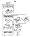
- Fig. 6 is a logic flow diagram of a computer program useful with the present invention.
- a basis polygon 10 represented as a triangle, includes vertices V 1 , V 2 and V 3 .
- this invention is not limited by the shape or number of sides of polygon 10, even though some CIG systems use only convex polygons for avoiding processing ambiguities.
- Polygon 10, including edges 12, 14 and 16 thereof, is used to define features of a scene to be displayed by a CIG system.
- Spatial orthogonal three-axis system polygon descriptors typically referenced to an orthogonal three-axis global system, are stored in a data base having a bulk storage medium, such as magnetic tape or disk.
- the polygon descriptors include x, y, z components of the vertices, along with other information such as color, texture and translucency for each polygon.
- Basis polygon 10 may be considered as a polygon of the lowest or least detailed LOD.
- Polygon 10 includes side 12 extending between vertices V 1 and V 2 , side 14 extending between vertices V 2 and V 3 , and side 16 extending between vertices V 1 and V 3 .
- Breakpoints 22, 24, and 26 may be the mid-points of sides 12, 14 and 16, respectively, or may be a predetermined fixed or random distance from a respective vertex in a clockwise or counterclockwise direction around polygon 10. That is, for a clockwise direction around polygon 10, breakpoint 22 may be determined with respect to V 1 , breakpoint 24 with respect to V 2 and breakpoint 26 with respect to V 3 .
- Fig. 1 Also shown for reference in Fig. 1 are the x and y axes of an orthogonal three-axis coordinate system with the origin at 0. The third or z-axis is perpendicular to the figure at origin 0 and is shown in Fig. 2.
- the x, y and z coordinates of vertices V 1 , V 2 and V 3 from which the x, y and z coordinates of break points 22, 24 and 26 are readily determinable, are available from a data base 60 (Fig. 5).
- the x, y and z coordinates of breakpoint 22 are the average of the sum of the respective x, y and z coordinates of vertices V 1 and V 2 , which are also the end points of side 12 of polygon 10 on which breakpoint 22 lies.
- the x, y and z coordinates for breakpoints 24 and 26 may likewise be determined from the coordinates of V 2 and V 3 for breakpoint 24, and from the coordinates of V 3 and V 1 for breakpoint 26.
- the coordinates of the breakpoint may be readily determined from the coordinates of the vertices of the end points of the side on which the breakpoint lies and the distance of the breakpoint from one of the vertices, using basic algebra, trigonometry and/or analytic geometry.
- processing may include, for example, programming a general purpose computer for determining the equation of a line (side) in three dimensions from the coordinates of the end points (vertices) of the line, and then determining the coordinates of a point (breakpoint) on the line (side) that is disposed at a predetermined distance from one of the end points (vertices) of the line (side).
- Breakpoints 22, 24 and 26 are shown interconnected by a series of dashed lines starting at one breakpoint and proceeding in a clockwise or counterclockwise direction until a closed polygon is obtained.
- FIG. 2 a view looking in the direction of the arrows of line 2-2 of Fig. 1 is shown.
- side 12 and treatment of breakpoint 22 is shown, it being understood that other breakpoints may be treated analogously.
- a deviation or perturbation value dz act is added or subtracted (-dz act ) from the z coordinate value of breakpoint 22 to form a derived vertex 21 when dz act is added to, or a derived vertex 23 when dz act is subtracted from, the z coordinate value of breakpoint 22.
- dz act a deviation or perturbation value
- -dz act a deviation or perturbation value
- breakpoint 22 is added or subtracted (-dz act ) from the z coordinate value of breakpoint 22 to form a derived vertex 21 when dz act is added to, or a derived vertex 23 when dz act is subtracted from, the z coordinate value of breakpoint 22.
- a deviation or perturbation value dz act is added or subtracted (-dz act ) from the z coordinate value of breakpoint 22 to form a derived vertex 21 when dz act is added to, or a derived vertex 23 when dz act is subtracted from, the z coordinate
- dz act dz tlu *K rz *K sz , wherein dz tlu is a base deviation value that may be obtained from a table look-up, K rz is a convergence factor having a value from 0 to 1 that varies continuously as a function of the breakup criteria and K sz is a scaling factor that ensures that the value of dz act does not exceed the value of maximum deviation dz max .
- the value of dz max may be determined in response to the length of the side of a polygon on which the breakpoint being modified is situated for ensuring that the value of dz act presents an acceptable image when displayed, as may be determined by one of ordinary skill in the art without undue experimentation.
- Scaling factor K sz is only required when dz tlu is a random deviation and may be set equal to one for all other cases.
- the value of dz act may be zero. For example, if polygon 10 abuts a cultural feature such as a road, then it may be desirable to supply a deviation dz act of zero to one or more breakpoints to avoid break-up of the cultural feature.
- a vertex created by the addition of dz act to the z coordinate of a breakpoint may be used to represent changes in elevation above a nominal elevation, such as rolling terrain, hills and valleys, while a vertex created by the subtraction of dz act from the z coordinate of a breakpoint may be used to represent relief in the terrain, such as a depression or crater.
- the present invention may be beneficially applied to features that generally do not require specific detail definition, such as terrain and bodies of water, it may be used to generate non-specific fine detail wherever such fine detail may be required or desired, without having to have previously determined or stored the fine detail when statistical data such as random or pseudo-random deviations are used.
- deterministic data that is data representing a specific or generic feature such as mountains, valleys and forests but not necessarily any particular real world feature, can be used to represent highly accurate images of the features.
- Another benefit of the present invention is that as the field of view changes, the fine detail that is generated in accordance with the present invention may be discarded without storing when the feature falls outside the field of view and may be later recreated should the feature again come within the field of view.
- the potential values for dz tlu may be determined and stored in a table look-up to be accessed by a code that is associated with each edge of basis polygon 10 (Fig. 1) and that is stored in the data base. If actual or deterministic data are used then some but not all data must be stored in the data base, such as elevation (z) but not x and y data which may be calculated. The code ensures that the same address is always selected for the edge.
- each dz tlu may be: a random or pseudo-random value; a predetermined constant; derived from real data, such as Defense Mapping Agency data; periodically changing, such as a sinusoidal function, for simulating, for example, waves in a body of water. More important than the actual source of values for dz tlu is that the image ultimately displayed appear to be realistic. It is well within the ability of one of ordinary skill in the art to select the type of deviation and values-or dz tlu that are suited for specific applications in accordance with the teachings of the present invention.
- a perspective view of basis polygon 10 of Fig. 1 having derived vertices in accordance with the present invention is shown.
- Derived vertices 21, and 27 correspond to breakpoints 22, 24, 26 respectively, with respective deviation values added to the z-components thereof.
- New edges 31 and 33 from derived vertex 21, new edges 37 and 38 from derived vertex 25, and new edges 43 and 45 from derived vertex 27 are indicated by dashed lines from the corresponding derived vertex to the end points of the side of basis polygon 10 on which the breakpoint corresponding to the derived vertex lies.
- Derived vertices 21, 25 and 27 are shown interconnected in a clockwise or counterclockwise direction starting with one of the derived vertices by dashed lines 35, 39 and 34 that form the sides of a closed derived polygon having vertices 21, 25 and 27.
- each of four derivative polygons defined by vertex triples V 2 , 21 and 25; V 1 , 21 and 27; V 3 , 25 and 27; 21, 25 and 27, may be processed for forming finer detail than is available from basis polygon 10 for visual images.
- Such processing is analogous to processing which occurs for polygon descriptors that are obtained from the data base.
- the derivative and derived polygons of Fig. 3A may be further subdivided for obtaining even finer detail.
- breakpoints 32, 34 and 36 are indicated on sides 31, 41 and 45 of one of the derivative polygons. Breakpoints may be similarly located on the sides of the other derivative and derived polygons and processing analogous to that used for the initial derived polygon obtained from basis polygon 10 may be employed.
- Point 52 represents a point lying within basis polygon 10.
- Point 52 may lie on an edge of basis polygon 10 if desired which is also considered to be within basis polygon 10.
- a deviation value 54 is combined with coordinate component values of point 52 for locating a derived vertex 56 lying outside the plane of basis polygon 10.
- Derived vertex 10 is shown connected to each vertex V 1 , V 2 and V 3 of basis polygon 10 by dashed lines 51, 53 and 55, respectively.
- Derivative polygons described by vertex triples V 1 , V 2 , 56; V 2 , V 3 , 56 and V 3 , V 1 , 56 may be processed for generating finer detail than is available from processing basis polygon 10. It is noted that when derived vertex 56 is connected to each vertex V 1 , V 2 and V 3 of basis polygon 10 the number of derivative polygons is equal to the number of sides of polygon 10.
- FIG. 4 a schematic diagram not necessarily to scale and including basis polygon 10 subdivided in response to predetermined ranges from a view point in accordance with the present invention is shown.
- a view point 40 is the center of concentric circular range rings 42, 44, 46 and 48, each disposed at a respective greater predetermined distance from viewpoint 40.
- the field of view (FOV) is represented by the smaller angle subtended by the margins 50 of the FOV.
- Basis polygon 10 is shown disposed between range rings 46 and 48. As basis polygon 10 moves toward viewpoint 40 and/or viewpoint 40 moves toward basis polygon 10 so that the relative position between basis polygon 30 and viewpoint 40 changes, and basis polygon 10 is disposed between range rings 44 and 46, additional detail may be required so that a first set of breakpoints for basis polygon 10 are determined. As the distance between basis polygon 10 and viewpoint 40 is further reduced so that basis polygon 10 lies between range rings 42 and 44, more additional detail is provided by determining a second set of breakpoints for the polygons created by the first set of derived vertices corresponding to the initial breakpoints of basis polygon 10 and determining a corresponding second set of derived vertices.
- basis polygon 10 is tested to determine if it lies within a predetermined functional range from viewpoint 40. If basis polygon 10 lies within the functional range, then at least one level of finer detail is allowed to be generated. For each additional level of breakup and resultant finer detail, basis polygon 10 must be within an additional closer range zone to viewpoint 40. In the alternative, an error function interval, such as one for elevation, may be used to determine when additional finer detail is required or permitted.
- a source terrain data such as the Defense Mapping Agency (DMA) supplies data covering large areas having the elevation thereof specified over a predetermined rectangular grid, typically having a spacing of 100 meters between elevation posts. It may be desired to have the elevation of the feature being displayed within a predetermined limit, or error function interval, from the actual elevation provided by the source of data. When the displayed elevation exceeds the error limit or falls outside the error interval then finer detail may be generated.
- DMA Defense Mapping Agency
- Convergence factor K r is used to moderate the introduction of additional detail so that the additional detail is gradually introduced into the scene as the range between viewpoint and basis polygon 10 changes to avoid a sudden appearance of additional detail into a scene.
- a data base 60 has an output connected to an input of a geometry processor 70 for supplying three dimensional polygon descriptors.
- Processor 70 includes an output connected to an input of display processor 80 for receiving two dimensional polygon descriptors from processor 70.
- An output of display processor 80 is connected to a video display 85 for supplying fully processed data that is ultimately displayed by video display 85.
- Detailed description of the operation of these components may be had by reference to U.S. Patents 4,811,245 - Bunker et al. and 4,825,391 - Merz, which are assigned to the present applicants.
- Another output of geometry processor 70 is connected to an input of breakpoint determinator circuitry 90 for receiving polygon descriptor information, while the outputs of breakpoint determinator circuitry 90 are connected to deviation circuitry 100 for supplying breakpoint data.
- Deviation circuitry 100 has outputs respectively connected to other inputs of geometry processor 70 for providing deviation data.
- the deviation data which include coordinates of new vertices as determined in accordance with the present invention, are processed by geometry processor analogously to the information regarding polygon vertices that is received as part of the polygon descriptor data from data base 60.
- Breakpoint data include information regarding the location of a breakpoint on an edge of a polygon with respect to a vertex of the polygon.
- breakpoint data may include information that the breakpoint is to be the midpoint of the edge, a random distance from the vertex, a periodically varying (like sinusoidal) distance from the vertex or other function that may be provided by operator input.
- Deviation circuitry 100, a deviation function selector 102, first scaling means 104, second scaling means 106 and combiner means 108 are connected in series for supplying deviation factor dx act to combiner means 108.
- First and second scaling means 104 and 106 scale the value of the signal provided thereto, such as by multiplying by the constant X rx and K sx , respectively.
- Also supplied to combiner 108 from an output of breakpoint determinator 90 is the coordinate value X bp of the x-coordinate of the breakpoint as determined by breakpoint determinator 90.
- Combiner means 108 combines, such as by adding or subtracting as selected (+/-), the value of the x-component X bp of the breakpoint with the actual deviation dx act from scaler 106 to form the x-component X nv of the coordinates of the new vertex 21 or 23 (Fig. 2).
- the output of combiner 108 which constitutes an output of deviation circuitry 100 and has the x-coordinate X nv of the new vertex is connected to an input of geometry processor 70.
- Analogous circuitry is available in deviation circuitry 100 for producing the y-coordinate Y nv and z-coordinate Z nv for new vertex 21 or 23 (Fig. 2) which are supplied to geometry processor 70.
- step 150 begins at step 150 and executes step 152 to obtain the vertices of the basis polygon.
- step 154 determines if the basis polygon is within the functional range. If it is not, the program returns to step 152. If the polygon is within the functional range, the execution of step 156 determines the breakpoints for each side of the basis polygon.
- Performance of step 158 determines if random deviation is to be used. If it is not to be used then K sz is set equal to one (along with K sx and K sy which are also set equal to one but have not been included in the figure to avoid undue clutter) and then proceeds to step 162. If random deviation is used, the program proceeds to step 162. Execution of step 162 determines the z-coordinate deviation dz act of the new vertex 21 or 23 (Fig. 2). The x- and y- coordinates of a new vertex are determined analogously to z-coordinate dz act but are not illustrated to avoid undue clutter. Performance of step 164 adds the deviation values determined by execution of step 162 to the coordinates of the breakpoint determined at step 156 for obtaining the coordinates of the new vertex.
- step 166 determines if another breakup level of the sides of the polygons defined by the vertices determined at step 164 for creating finer detail is desired. If it is not, then step 168 is performed to process the new polygons for display and execution of step 170 determines if the basis polygon being processed is the last polygon to be processed. If it is, the program ends. If it is not the last polygon, the program returns to step 152, to repeat steps 152 - 170 as described above and step 172, if required, as described below.
- step 172 determines if the basis polygon is within the next level (closer) range ring from the range of step 154. If it is not, then step 168 is performed and processing proceeds as described above. If the basis polygon is within the next level range ring when step 172 is performed, then step 156 is executed to determine the breakpoints of the polygon defined by the vertices determined at the last performance of step 164. Steps 156-172 are repeated as required until testing at step 170 indicates that the last polygon has been processed.
Landscapes
- Engineering & Computer Science (AREA)
- Computer Graphics (AREA)
- Physics & Mathematics (AREA)
- General Physics & Mathematics (AREA)
- Theoretical Computer Science (AREA)
- Image Generation (AREA)
- Processing Or Creating Images (AREA)
Claims (19)
- Procédé pour obtenir une transition de niveau de détail régulière et sensiblement continue dans un système de production d'images par ordinateur dans lequel les particularités des objets d'une image affichée sont formées par des premiers polygones plans, ayant tous une pluralité de premiers sommets dont chacun représente un point d'extrémité de chaque côté de l'un des premiers polygones, le procédé comprenant les étapes consistant à :(a) retrouver dans une mémoire des données déterminant chacun des premiers sommets de chacun des premiers polygones,(b) partager chacun de certains au moins des premiers polygones en une pluralité de seconds polygones plans, tous plus petits que le premier polygone associé, chaque second polygone ayant au moins un deuxième sommet qui est placé à la jonction formée par deux côtés de ce second polygone et chaque deuxième sommet étant différent de n'importe lequel des premiers sommets,(c) placer, pour l'un au moins sélectionné des deuxièmes sommets, un troisième sommet dérivé correspondant, situé à une certaine valeur d'écart à l'extérieur du plan commun des premiers et deuxièmes polygones associés et différent de n'importe lequel des premiers sommets mémorisés,(d) afficher au moins un polygone plan dérivé, tous définis par une combinaison différente de l'un des troisièmes sommets déterminés à l'étape (c) et de ceux associés des premiers et deuxièmes sommets, pour créer et afficher certaines au moins des scènes d'une séquence de scènes d'une image visible, et(e) faire varier la valeur d'écart de manière à afficher des scènes ayant un niveau de détail croissant à mesure que le point d'observation s'approche de l'emplacement d'un polygone, et avec une transition de niveau de détail régulière et sensiblement continue.
- Procédé selon la revendication 1, dans lequel chaque deuxième sommet a une composante d'élévation qui lui est associée et l'étape (c) comprend l'étape consistant à placer l'un au moins des troisièmes sommets de telle sorte que la donnée de composante d'élévation de ce troisième sommet soit différente de la donnée de composante d'élévation de son deuxième sommet associé.
- Procédé selon la revendication 2, dans lequel la donnée de composante d'élévation du troisième sommet sélectionné est supérieure à la donnée de composante d'élévation de son deuxième sommet associé.
- Procédé selon la revendication 3, dans lequel la donnée de composante d'élévation du troisième sommet sélectionné est inférieure à la donnée de composante d'élévation de son deuxième sommet associé.
- Procédé selon la revendication 1, dans lequel l'étape (b) comprend l'étape consistant à casser certains au moins des premiers polygones en des deuxièmes polygones uniquement lorsque l'angle, formé entre un point d'observation de l'image et à la fois un point de visée d'une fenêtre d'observation et un rayon d'observation allant vers ledit premier polygone, se trouve dans des limites prédéterminées.
- Procédé selon la revendication 1, dans lequel chaque polygone est un triangle.
- Procédé selon la revendication 1, dans lequel les points de cassure et les sommets dérivés sont décrits dans un référentiel à trois axes mutuellement orthogonaux et l'étape (c) comprend les étapes consistant à :(c1) obtenir des données de valeur d'écart pour chaque point de cassure, et(c2) combiner la donnée de valeur d'écart obtenue pour un point de cassure particulier avec une donnée correspondant à une coordonnée d'axe du point de cassure afin d'obtenir une donnée établissant la coordonnée réelle du sommet dérivé le long de ce même axe.
- Procédé selon la revendication 7, dans lequel l'étape de combinaison (c2) comprend l'étape consistant à ajouter une valeur de donnée d'écart associée à chacune d'au moins une valeur de donnée différente des trois valeurs de données axiales du référentiel à trois axes orthogonaux utilisées pour identifier la position du point de cassure.
- Procédé selon la revendication 7, dans lequel l'étape de combinaison (c2) comprend l'étape consistant à soustraire une valeur de donnée d'écart associée à chacune d'au moins une valeur de donnée différente des trois valeurs de données axiales du référentiel à trois axes orthogonaux utilisées pour identifier la position du point de cassure.
- Procédé selon la revendication 7, dans lequel la valeur d'écart est choisie dans le groupe comprenant :- des valeurs constantes prédéterminées,- des valeurs aléatoires,- des valeurs sinusoïdales prédéterminées,- d'autres valeurs périodiques prédéterminées,- des valeurs géospécifiques de terrain, et- une combinaison de ces valeurs.
- Procédé selon la revendication 1, dans lequel l'étape (c) comprend l'étape consistant à assigner à chaque troisième sommet différent une distance prédéterminée le long d'un côté présélectionné différent partant d'un sommet présélectionné associé du polygone de base.
- Procédé selon la revendication 11, dans lequel la distance prédéterminée est choisie dans le groupe comprenant :- la moitié de la longueur du côté correspondant,- une distance constante prédéterminée,- une distance aléatoire, et- une combinaison de ces valeurs.
- Procédé selon la revendication 1, dans lequel :- l'étape (c) comprend en outre l'étape (c') consistant à traiter les données totales pour déterminer d'autres points de cassure, chaque autre point de cassure se trouvant sur un côté correspondant du polygone dérivé,- l'étape (d) comprend en outre l'étape (d') consistant à modifier de manière sensiblement continue les données pour l'un au moins des autres points de cassure afin de former des données désignant un autre sommet dérivé qui est placé à l'extérieur du plan des deux polygones, le polygone dérivé et le polygone de base, et- l'étape (e) comprend en outre l'étape (e') consistant à inclure les autres données de sommet dérivé dans les données de sommet augmentées.
- Procédé selon la revendication 13, dans lequel :- l'étape (c) n'est effectuée que lorsque le polygone de base est dans les limites d'une première distance prédéterminée par rapport au point d'observation, et- l'étape (c') de traitement des données pour déterminer d'autres points de cassure n'est effectuée que lorsque le polygone considéré est dans les limites d'une deuxième distance prédéterminée, plus proche du point d'observation que la première distance prédéterminée.
- Procédé selon la revendication 1, dans lequel l'étape (c) n'est effectuée que lorsque le polygone de base est dans les limites d'une distance prédéterminée par rapport au point d'observation.
- Procédé selon la revendication 1, dans lequel l'étape (c) comprend en outre l'étape consistant à déterminer ledit point de cassure au nombre d'au moins un uniquement lorsque l'angle entre un point de visée d'une fenêtre d'observation et un rayon d'observation allant vers le polygone impliqué, tous deux par rapport au point d'observation, est dans des limites prédéterminées.
- Procédé d'augmentation pour un système de production d'images par ordinateur dans lequel les particularités des objets d'une image à afficher sont représentées par des polygones de base plans, ayant des sommets qui représentent des points d'extrémité de chaque côté d'une pluralité de côtés des polygones de base, le procédé servant à augmenter le nombre total de sommets pour provoquer une augmentation du nombre total de polygones, tous avec un détail plus fin des particularités des objets, devant être affichés avec une transition de niveau de détail régulière et sensiblement continue dans des scènes visibles produites par le système, et comprenant les étapes consistant à:(a) retrouver dans une mémoire des données de sommets définissant chacun des polygones de base de la pluralité,(b) choisir un point situé dans chacun d'au moins un polygone de base sélectionné et différent de n'importe lequel des sommets du polygone de base associé,(c) placer un sommet dérivé situé à une certaine distance d'écart à l'extérieur du plan du polygone de base associé au niveau du point sélectionné et différent de n'importe lequel des sommets des polygones de base mémorisés,(d) former au moins un polygone dérivé, déterminé par le sommet dérivé et au moins deux sommets adjacents du polygone de base associé, en réponse au fait que la position du polygone de base associé s'approche d'un point d'observation dans l'image, et(e) afficher le polygone dérivé comme une partie de l'image visible d'une scène ayant un niveau de détail des particularités plus fin et une transition de niveau de détail régulière et sensiblement continue à mesure que la distance entre la position du polygone et le point d'observation diminue.
- Procédé selon la revendication 17, dans lequel l'étape (e) comprend les étapes consistant à :- former une pluralité de polygones dérivés, contenant tous le sommet dérivé et un côté du polygone de base associé, le nombre de polygones dérivés de la pluralité étant égal au nombre de côtés du polygone de base, et- afficher la pluralité de polygones dérivés pour obtenir l'image affichée.
- Procédé selon la revendication 17, dans lequel l'étape (b) comprend en outre l'étape consistant à choisir chaque point du polygone de base uniquement quand l'angle, formé entre un point d'observation de l'image et à la fois un point de visée d'une fenêtre d'observation et un rayon d'observation allant vers ledit polygone de base, se trouve dans des limites prédéterminées.
Applications Claiming Priority (2)
| Application Number | Priority Date | Filing Date | Title |
|---|---|---|---|
| US37768789A | 1989-07-10 | 1989-07-10 | |
| US377687 | 1989-07-10 |
Publications (3)
| Publication Number | Publication Date |
|---|---|
| EP0408232A2 EP0408232A2 (fr) | 1991-01-16 |
| EP0408232A3 EP0408232A3 (en) | 1992-09-23 |
| EP0408232B1 true EP0408232B1 (fr) | 1997-12-10 |
Family
ID=23490135
Family Applications (1)
| Application Number | Title | Priority Date | Filing Date |
|---|---|---|---|
| EP90307232A Expired - Lifetime EP0408232B1 (fr) | 1989-07-10 | 1990-07-02 | Augmentation spatiale de sommets pour la transition de niveaux de détail |
Country Status (6)
| Country | Link |
|---|---|
| EP (1) | EP0408232B1 (fr) |
| JP (1) | JP2852813B2 (fr) |
| CA (1) | CA2020550A1 (fr) |
| DE (1) | DE69031789T2 (fr) |
| IL (1) | IL94890A (fr) |
| WO (1) | WO1991001529A1 (fr) |
Families Citing this family (1)
| Publication number | Priority date | Publication date | Assignee | Title |
|---|---|---|---|---|
| JP2002279449A (ja) * | 2001-03-19 | 2002-09-27 | Mitsubishi Electric Corp | 3次元空間データ送信表示装置、3次元空間データ送信方法、3次元空間データ送信方法をコンピュータに実行させるためのプログラムを記録したコンピュータ読み取り可能な記録媒体 |
Family Cites Families (7)
| Publication number | Priority date | Publication date | Assignee | Title |
|---|---|---|---|---|
| US4291380A (en) * | 1979-05-14 | 1981-09-22 | The Singer Company | Resolvability test and projection size clipping for polygon face display |
| IL72685A (en) * | 1983-08-30 | 1988-08-31 | Gen Electric | Advanced video object generator |
| US4821212A (en) * | 1984-08-08 | 1989-04-11 | General Electric Company | Three dimensional texture generator for computed terrain images |
| US4715005A (en) * | 1984-08-08 | 1987-12-22 | General Electric Company | Terrain/seascape image generator with math model data base |
| US4646251A (en) * | 1985-10-03 | 1987-02-24 | Evans & Sutherland Computer Corporation | Computer graphics, parametric patch parallel subdivision processor |
| US4912664A (en) * | 1988-02-01 | 1990-03-27 | Mentor Graphics Corporation | Method and apparatus for generating a mesh for finite element analysis |
| US4933889A (en) * | 1988-04-29 | 1990-06-12 | International Business Machines Corporation | Method for fine decomposition in finite element mesh generation |
-
1990
- 1990-06-22 JP JP3500351A patent/JP2852813B2/ja not_active Expired - Lifetime
- 1990-06-22 WO PCT/US1990/003567 patent/WO1991001529A1/fr not_active Ceased
- 1990-06-27 IL IL9489090A patent/IL94890A/en active IP Right Grant
- 1990-07-02 DE DE69031789T patent/DE69031789T2/de not_active Expired - Fee Related
- 1990-07-02 EP EP90307232A patent/EP0408232B1/fr not_active Expired - Lifetime
- 1990-07-05 CA CA002020550A patent/CA2020550A1/fr not_active Abandoned
Also Published As
| Publication number | Publication date |
|---|---|
| IL94890A0 (en) | 1991-04-15 |
| IL94890A (en) | 1995-12-31 |
| WO1991001529A1 (fr) | 1991-02-07 |
| EP0408232A2 (fr) | 1991-01-16 |
| EP0408232A3 (en) | 1992-09-23 |
| JPH04500878A (ja) | 1992-02-13 |
| JP2852813B2 (ja) | 1999-02-03 |
| DE69031789D1 (de) | 1998-01-22 |
| DE69031789T2 (de) | 1998-07-02 |
| CA2020550A1 (fr) | 1991-01-11 |
Similar Documents
| Publication | Publication Date | Title |
|---|---|---|
| US5367615A (en) | Spatial augmentation of vertices and continuous level of detail transition for smoothly varying terrain polygon density | |
| Appel et al. | The haloed line effect for hidden line elimination. | |
| US5841441A (en) | High-speed three-dimensional texture mapping systems and methods | |
| KR910009101B1 (ko) | 화상합성장치 | |
| US5630718A (en) | Weather simulation system | |
| JP2667835B2 (ja) | コンピユータグラフイツクス表示装置 | |
| US4855934A (en) | System for texturing computer graphics images | |
| US3602702A (en) | Electronically generated perspective images | |
| US4291380A (en) | Resolvability test and projection size clipping for polygon face display | |
| US5598359A (en) | Weather effects generator for simulation systems | |
| US4179823A (en) | Real-time simulation of a polygon face object system as viewed by a moving observer | |
| JP3759971B2 (ja) | 3次元像を陰影付けする方法 | |
| EP0137107A1 (fr) | Système générateur d'images par ordinateur | |
| US5409379A (en) | Weather simulation system | |
| US4179824A (en) | Simulation of an object system formed by polygon faces having a series of fundamental shapes and dimension | |
| US5003497A (en) | Method for three-dimensional clip checking for computer graphics | |
| GB2243523A (en) | Generating elliptical objects | |
| EP0314368B1 (fr) | Méthode et appareil de suppression des surfaces cachées | |
| US5664077A (en) | Three-dimensional graph displaying system | |
| EP0408232B1 (fr) | Augmentation spatiale de sommets pour la transition de niveaux de détail | |
| US6590582B1 (en) | Clipping processing method | |
| EP0250588B1 (fr) | Correction d'ensemble de distorsions dans un systeme d'imagerie en temps reel | |
| CA2065736C (fr) | Augmentation spatiale du nombre de sommets et continuite des transitions dans les polygones de representation de terrains | |
| JP2952585B1 (ja) | 画像生成方法 | |
| Cooley | The essence of computer graphics |
Legal Events
| Date | Code | Title | Description |
|---|---|---|---|
| PUAI | Public reference made under article 153(3) epc to a published international application that has entered the european phase |
Free format text: ORIGINAL CODE: 0009012 |
|
| AK | Designated contracting states |
Kind code of ref document: A2 Designated state(s): DE FR GB IT |
|
| PUAL | Search report despatched |
Free format text: ORIGINAL CODE: 0009013 |
|
| AK | Designated contracting states |
Kind code of ref document: A3 Designated state(s): DE FR GB IT |
|
| 17P | Request for examination filed |
Effective date: 19930318 |
|
| 17Q | First examination report despatched |
Effective date: 19950905 |
|
| GRAG | Despatch of communication of intention to grant |
Free format text: ORIGINAL CODE: EPIDOS AGRA |
|
| GRAG | Despatch of communication of intention to grant |
Free format text: ORIGINAL CODE: EPIDOS AGRA |
|
| GRAH | Despatch of communication of intention to grant a patent |
Free format text: ORIGINAL CODE: EPIDOS IGRA |
|
| GRAH | Despatch of communication of intention to grant a patent |
Free format text: ORIGINAL CODE: EPIDOS IGRA |
|
| GRAA | (expected) grant |
Free format text: ORIGINAL CODE: 0009210 |
|
| AK | Designated contracting states |
Kind code of ref document: B1 Designated state(s): DE FR GB IT |
|
| ET | Fr: translation filed | ||
| REF | Corresponds to: |
Ref document number: 69031789 Country of ref document: DE Date of ref document: 19980122 |
|
| ITF | It: translation for a ep patent filed | ||
| PLBE | No opposition filed within time limit |
Free format text: ORIGINAL CODE: 0009261 |
|
| STAA | Information on the status of an ep patent application or granted ep patent |
Free format text: STATUS: NO OPPOSITION FILED WITHIN TIME LIMIT |
|
| 26N | No opposition filed | ||
| REG | Reference to a national code |
Ref country code: GB Ref legal event code: IF02 |
|
| REG | Reference to a national code |
Ref country code: GB Ref legal event code: 732E |
|
| REG | Reference to a national code |
Ref country code: GB Ref legal event code: 732E |
|
| REG | Reference to a national code |
Ref country code: GB Ref legal event code: 732E |
|
| REG | Reference to a national code |
Ref country code: FR Ref legal event code: TP |
|
| PGFP | Annual fee paid to national office [announced via postgrant information from national office to epo] |
Ref country code: DE Payment date: 20070831 Year of fee payment: 18 |
|
| PGFP | Annual fee paid to national office [announced via postgrant information from national office to epo] |
Ref country code: GB Payment date: 20070727 Year of fee payment: 18 |
|
| PGFP | Annual fee paid to national office [announced via postgrant information from national office to epo] |
Ref country code: IT Payment date: 20070730 Year of fee payment: 18 |
|
| PGFP | Annual fee paid to national office [announced via postgrant information from national office to epo] |
Ref country code: FR Payment date: 20070717 Year of fee payment: 18 |
|
| GBPC | Gb: european patent ceased through non-payment of renewal fee |
Effective date: 20080702 |
|
| PG25 | Lapsed in a contracting state [announced via postgrant information from national office to epo] |
Ref country code: DE Free format text: LAPSE BECAUSE OF NON-PAYMENT OF DUE FEES Effective date: 20090203 |
|
| REG | Reference to a national code |
Ref country code: FR Ref legal event code: ST Effective date: 20090331 |
|
| PG25 | Lapsed in a contracting state [announced via postgrant information from national office to epo] |
Ref country code: GB Free format text: LAPSE BECAUSE OF NON-PAYMENT OF DUE FEES Effective date: 20080702 |
|
| PG25 | Lapsed in a contracting state [announced via postgrant information from national office to epo] |
Ref country code: IT Free format text: LAPSE BECAUSE OF NON-PAYMENT OF DUE FEES Effective date: 20080702 Ref country code: FR Free format text: LAPSE BECAUSE OF NON-PAYMENT OF DUE FEES Effective date: 20080731 |