EP0408244B1 - Faseroptische Kabelverbindung - Google Patents
Faseroptische Kabelverbindung Download PDFInfo
- Publication number
- EP0408244B1 EP0408244B1 EP90307324A EP90307324A EP0408244B1 EP 0408244 B1 EP0408244 B1 EP 0408244B1 EP 90307324 A EP90307324 A EP 90307324A EP 90307324 A EP90307324 A EP 90307324A EP 0408244 B1 EP0408244 B1 EP 0408244B1
- Authority
- EP
- European Patent Office
- Prior art keywords
- joint
- cable
- collars
- taper
- outer taper
- Prior art date
- Legal status (The legal status is an assumption and is not a legal conclusion. Google has not performed a legal analysis and makes no representation as to the accuracy of the status listed.)
- Expired - Lifetime
Links
- 239000013307 optical fiber Substances 0.000 title claims description 14
- 230000005540 biological transmission Effects 0.000 claims description 16
- 239000000835 fiber Substances 0.000 claims description 12
- 230000002401 inhibitory effect Effects 0.000 claims description 3
- 239000004020 conductor Substances 0.000 claims 4
- 239000002184 metal Substances 0.000 description 9
- 229910052751 metal Inorganic materials 0.000 description 9
- RYGMFSIKBFXOCR-UHFFFAOYSA-N Copper Chemical compound [Cu] RYGMFSIKBFXOCR-UHFFFAOYSA-N 0.000 description 7
- 229910052802 copper Inorganic materials 0.000 description 7
- 239000010949 copper Substances 0.000 description 7
- 238000000576 coating method Methods 0.000 description 5
- 238000009413 insulation Methods 0.000 description 5
- 229910001209 Low-carbon steel Inorganic materials 0.000 description 4
- 239000011248 coating agent Substances 0.000 description 3
- 230000003287 optical effect Effects 0.000 description 3
- 229910000851 Alloy steel Inorganic materials 0.000 description 2
- 239000004698 Polyethylene Substances 0.000 description 2
- 229910000831 Steel Inorganic materials 0.000 description 2
- 230000000903 blocking effect Effects 0.000 description 2
- 239000004033 plastic Substances 0.000 description 2
- 229920003023 plastic Polymers 0.000 description 2
- -1 polyethylene Polymers 0.000 description 2
- 229920000573 polyethylene Polymers 0.000 description 2
- 238000002360 preparation method Methods 0.000 description 2
- 239000010959 steel Substances 0.000 description 2
- XLYOFNOQVPJJNP-UHFFFAOYSA-N water Substances O XLYOFNOQVPJJNP-UHFFFAOYSA-N 0.000 description 2
- NIXOWILDQLNWCW-UHFFFAOYSA-M Acrylate Chemical compound [O-]C(=O)C=C NIXOWILDQLNWCW-UHFFFAOYSA-M 0.000 description 1
- 239000000853 adhesive Substances 0.000 description 1
- 230000001070 adhesive effect Effects 0.000 description 1
- 230000004323 axial length Effects 0.000 description 1
- 230000015556 catabolic process Effects 0.000 description 1
- 229940126214 compound 3 Drugs 0.000 description 1
- 150000001875 compounds Chemical class 0.000 description 1
- 230000006835 compression Effects 0.000 description 1
- 238000007906 compression Methods 0.000 description 1
- 238000010276 construction Methods 0.000 description 1
- 238000006731 degradation reaction Methods 0.000 description 1
- 230000000694 effects Effects 0.000 description 1
- 238000010292 electrical insulation Methods 0.000 description 1
- 238000000465 moulding Methods 0.000 description 1
- 230000001681 protective effect Effects 0.000 description 1
- 229910000679 solder Inorganic materials 0.000 description 1
- 238000004804 winding Methods 0.000 description 1
Images

Classifications
-
- G—PHYSICS
- G02—OPTICS
- G02B—OPTICAL ELEMENTS, SYSTEMS OR APPARATUS
- G02B6/00—Light guides; Structural details of arrangements comprising light guides and other optical elements, e.g. couplings
- G02B6/24—Coupling light guides
- G02B6/255—Splicing of light guides, e.g. by fusion or bonding
- G02B6/2558—Reinforcement of splice joint
-
- G—PHYSICS
- G02—OPTICS
- G02B—OPTICAL ELEMENTS, SYSTEMS OR APPARATUS
- G02B6/00—Light guides; Structural details of arrangements comprising light guides and other optical elements, e.g. couplings
- G02B6/24—Coupling light guides
- G02B6/36—Mechanical coupling means
- G02B6/38—Mechanical coupling means having fibre to fibre mating means
- G02B6/3807—Dismountable connectors, i.e. comprising plugs
- G02B6/3887—Anchoring optical cables to connector housings, e.g. strain relief features
- G02B6/3888—Protection from over-extension or over-compression
-
- G—PHYSICS
- G02—OPTICS
- G02B—OPTICAL ELEMENTS, SYSTEMS OR APPARATUS
- G02B6/00—Light guides; Structural details of arrangements comprising light guides and other optical elements, e.g. couplings
- G02B6/24—Coupling light guides
- G02B6/36—Mechanical coupling means
- G02B6/38—Mechanical coupling means having fibre to fibre mating means
- G02B6/3807—Dismountable connectors, i.e. comprising plugs
- G02B6/3887—Anchoring optical cables to connector housings, e.g. strain relief features
- G02B6/3889—Anchoring optical cables to connector housings, e.g. strain relief features using encapsulation for protection, e.g. adhesive, molding or casting resin
Definitions
- a plurality of metal wires 4 e.g. of copper, which have been drawn down to a substantially sector-shaped cross-section so that they each fit together and form a crush-resistant electrically conductive tube around the tube 2.
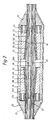
- the joint of Figs. 2 and 3 comprises a hollow integral one-piece metal rigid insert 26 having a cylindrical bore 26A and outward conical tapers 26B towards opposite ends. At the very ends of this insert the outer surface is more tapered as shown at 26C in Fig. 3 of the drawings.
- a carbide grit coating 26D similar to that discussed in our Pending Patent Application EP-A-368 639 (C.J. Brown 1).
- each end has a soft-metal nose cone 26E to provide stress relief where the wires 6A leave the insert 26.
- the cable is prepared and the joint is assembled as follows.
- the cable ends are then ready for jointing.
- the longitudinally slotted reinstatement tubular member 10 (the slot 10A is visible in Fig. 2 and is in the plane of the Figure) is fitted over the spliced fibre and the exposed metal tube 2 and reinstates those copper wires 4 which have been cut away.
- As strong adhesive is used in the slot to secure the steel alloy tubes 2.
- the metal ferrules 27 are slid partly over the member 10 (both 27 and 10 are made of beryillium copper in this embodiment) and left partly over the respective ends of the copper wires 4 and flooded with solder. At this point the cable ends are firmly fixed together by means of the member 10 and ferrules 27.
- the intermediate inserts 25 are then fitted over the wires 6A, the outer wires 6B are restranded, and the collars 24 fitted over to hold the outer wires in place.
- the assembly is then put in a pressing tool which presses axially the collars 24 towards each other, applying a predetermined actuating load.
- This securely grips the strand wires 6A, 6B, without moving the strand wires 6A relative axially to the ferrule 26 and the optical package because the high friction of the rough surface provided by the carbide coating causes much greater friction on the wires than does the surface of the collar, which thus slides relatively easily to effect the wedging action.
Landscapes
- Physics & Mathematics (AREA)
- General Physics & Mathematics (AREA)
- Optics & Photonics (AREA)
- Engineering & Computer Science (AREA)
- Plasma & Fusion (AREA)
- Mechanical Coupling Of Light Guides (AREA)
- Cable Accessories (AREA)
- Light Guides In General And Applications Therefor (AREA)
Claims (5)
- Kabelverbindung zur Verbindung gegenüberliegender Enden eines faseroptischen Seekabels, das ein in der Mitte liegendes faseroptisches Übertragungselement und eine ZugfestigkeitsDrahtlage mit kreisförmigem Querschnitt umfaßt, die das Übertragungselement umgibt, wobei die Kabelverbindung ein rohrförmiges Element (26) mit einer Bohrung (26A) zur Aufnahme der miteinander verbundenen Übertragungselemente der gegenüberliegenden Kabelenden und mit einer äußeren konischen Verjüngung (26B) an jedem Ende und erste und zweite Hülsen (24) einschließt, die jeweils eine konisch verlaufende Bohrung (24A) aufweisen, die dem jeweiligen äußeren konischen Verlauf des rohrförmigen Elementes angepaßt ist, so daß während des anfänglichen Zusammenbaus die ersten und zweiten Hülsen durch eine Ausübung eines axialen Druckes auf diese gegeneinander gedrückt werden können, um gegenüberliegende Endteile der Zugfestigkeitslage gegen die jeweilige äußere konische Verjüngung zu drücken, wobei die Kabelverbindung weiterhin Halteeinrichtungen (23) zum Festhalten der ersten und zweiten Hülsen in ihrer Klemmstellung einschließt und eine äußere wasserdichte Gehäusestruktur zum Umschließen der Kabelverbindung umfaßt,
dadurch gekennzeichnet, daß jede äußere konische Verjüngung eine eine hohe Reibung aufweisende Oberfläche (26D) aufweist, die durch ein hartes, mit der sich konisch verjüngenden Oberfläche fest verbundenes Körnermaterial gebildet ist, wobei die eine hohe Reibung aufweisende Oberfläche jeder äußeren konischen Verjüngung eine nach innen gerichtete Bewegung der Zugfestigkeitslage gegenüber den äußeren Verjüngungen verhindert, wodurch das Aufbringen einer Kompressionskraft auf das Übertragungselement im Inneren der Kabelverbindung während des anfänglichen Zusammenbaus im wesentlichen beseitigt wird. - Kabelverbindung zur Verbindung gegenüberliegender Enden eines faseroptischen Seekabels mit einem in der Mitte liegenden faseroptischen Übertragungselement und ersten und zweiten Zugfestigkeits-Drahtlagen mit kreisförmigem Querschnitt, die das Übertragungselement umgeben, wobei die Kabelverbindung ein rohrförmiges Element (26) mit einer Bohrung (26A) zur Aufnahme der miteinander verbundenen Übertragungselemente der gegenüberliegenden Kabelenden und mit einer äußeren verjüngung (26B) an jedem Ende, erste und zweite konisch verjüngte Einsätze (25), deren Form der äußeren Verjüngung (26B) des rohrförmigen Elementes entspricht und die jeweils so ausgebildet sind, daß sie zwischen die ersten und zweiten Zugfestigkeits-Drahtlagen des entsprechenden Kabelendes passen, und erste und zweite Hülsen (24) einschließt, die jeweils eine konisch verlaufende Bohrung (24A) aufweisen, die an die jeweilien äußere Verjüngung des rohrförmigen Elementes angepaßt ist, so daß während des anfänglichen Zusammenbaus die ersten und zweiten Hülsen durch die Ausübung eines axialen Druckes auf diese gegeneinander gedrückt werden können, um gegenüberliegnde Endteile jeder der ersten Zugfestigkeits-Drahtlagen zwischen dem jeweiligen verjüngten Einsatz und der äußeren konischen Verjüngung des rohrförmigen Elementes einzuklemmen, und um gegenüberliegende Endteile jeder der zweiten Zugfestigkeits-Drahtlagen zwischen der jeweiligen Hülse und dem verjüngten Einsatz einzuklemmen, wobei die Kabelverbindung weiterhin mit dem Gehäuse verbundene Halteeinrichtungen (23) zum Festhalten der ersten und zweiten Hülsen in ihrer Klemmstellung einschließt und eine äußere wasserdichte Gehäusestruktur aufweist, dadurch gekennzeichnet, daß jede der äußeren konischen Verjüngungen eine eine hohe Reib ung aufweisende Oberfläche (26D) aufweist, die durch ein hartes Körnermaterial gebildet, das mit der sich verjüngenden Oberfläche fest verbunden ist, wobei die eine hohe Reibung aufweisende Oberfläche jeder der äußeren konischen Verjüngungen eine nach innen gerichtete Bewegung der ersten ZugfestigkeitsDrahtlagen gegenüber den äußeren konisch verlaufenden Verjüngungen verhindert, so daß im wesentlichen die Ausübung einer Kompressionskraft auf das Übertragungselement innerhalb der Kabelverbindung während des anfänglichen Zusammenbaus beseitigt wird.
- Kabelverbindung nach Anspruch 1 oder 2,
dadurch gekennzeichnet, daß jede äußere Verjüngung (26B) einen Nasenkegel (26C) aufweist, der weicher als der erste Teil (26) ist. - Kabelverbindung nach einem der vorhergehenden Ansprüche, bei dem die optische Faser in einem rohrförmigen Leiter des Kabels untergebracht ist,
dadurch gekennzeichnet, daß die Kabelverbindung ein leitendes Rohr (10) zur Anordnung zwischen den gegenüberliegenden Enden des rohrförmigen Leiters (4) umfaßt, und daß dünne leitende Endhülsen (27) teilweise über den Leiter und teilweise über das benachbarte Ende des Rohres aufgesetzt sind und mit beiden verlötbar sind, um dem rohrförmigen Leiter (4) innerhalb der Kabelverbindung wieder instandzusetzen. - Kabelverbindung nach einem der vorhergehenden Ansprüche, dadurch gekennzeichnet, daß die Halteeinrichtungen ein Überbrückungselement (32), das an jedem Ende ein Innengewinde aufweist, und zwei mit Außengewinde versehene Muttern (23) umfassen, die in das Element (32) eingeschraubt sind, um mit den Klemmteilen (24) in Eingriff zu kommen.
Applications Claiming Priority (2)
| Application Number | Priority Date | Filing Date | Title |
|---|---|---|---|
| GB8916132 | 1989-07-14 | ||
| GB8916132A GB2233782B (en) | 1989-07-14 | 1989-07-14 | Optical fibre cable joint |
Publications (3)
| Publication Number | Publication Date |
|---|---|
| EP0408244A2 EP0408244A2 (de) | 1991-01-16 |
| EP0408244A3 EP0408244A3 (en) | 1991-08-28 |
| EP0408244B1 true EP0408244B1 (de) | 1994-05-18 |
Family
ID=10660040
Family Applications (1)
| Application Number | Title | Priority Date | Filing Date |
|---|---|---|---|
| EP90307324A Expired - Lifetime EP0408244B1 (de) | 1989-07-14 | 1990-07-04 | Faseroptische Kabelverbindung |
Country Status (7)
| Country | Link |
|---|---|
| US (1) | US5048921A (de) |
| EP (1) | EP0408244B1 (de) |
| JP (1) | JP2938157B2 (de) |
| AU (1) | AU623542B2 (de) |
| DE (1) | DE69008948T2 (de) |
| DK (1) | DK0408244T3 (de) |
| GB (1) | GB2233782B (de) |
Families Citing this family (16)
| Publication number | Priority date | Publication date | Assignee | Title |
|---|---|---|---|---|
| GB8922354D0 (en) * | 1989-10-04 | 1989-11-22 | British Telecomm | Cable joint |
| US5185844A (en) * | 1991-07-29 | 1993-02-09 | At&T Bell Laboratories | Closure for optical fiber connective arrangements and method of providing same |
| FR2693805B1 (fr) * | 1992-07-16 | 1994-09-02 | Alcatel Cable | Boîte de jonction de câbles optiques sous-marins. |
| US5315682A (en) * | 1992-07-16 | 1994-05-24 | Alcatel Cable | Splice device for splicing together under-sea optical cables |
| US6272273B1 (en) | 1999-09-02 | 2001-08-07 | Alcatel | Hermetic cable joint |
| US6558044B1 (en) * | 2000-02-23 | 2003-05-06 | Global Pacific Group Ltd. | Optical fiber inner tube connector |
| JP4554838B2 (ja) * | 2001-04-03 | 2010-09-29 | 株式会社ジャパンリーコム | 光ケーブル接続部収納用キャビネット |
| US6722790B2 (en) * | 2002-01-04 | 2004-04-20 | Panduit Corp. | Contoured internal stub crimp backbone |
| CN100380152C (zh) * | 2003-11-07 | 2008-04-09 | 长飞光纤光缆有限公司 | 一种敷设于下水管道中的光缆及其敷设方法 |
| US7393148B2 (en) * | 2005-12-06 | 2008-07-01 | Tyco Electronics Corporation | Optical fiber splicing closures and methods |
| US8944658B1 (en) * | 2009-09-11 | 2015-02-03 | The Boeing Company | LED holder for lighting panels |
| WO2017161185A1 (en) | 2016-03-17 | 2017-09-21 | Ormond Energy Innovations Inc. | Protective fiber optic termination, system, and method of using same |
| USD828861S1 (en) | 2016-04-13 | 2018-09-18 | Global Marine Systems Limited | Fiber optic joint |
| US11404815B2 (en) | 2017-10-30 | 2022-08-02 | Ormond Energy Innovations Inc. | Sealed connector with triggered mating and method of using same |
| JP2020183978A (ja) * | 2019-04-26 | 2020-11-12 | パナソニックIpマネジメント株式会社 | 接続装置、ケーブル装置及び照明器具 |
| US11858220B2 (en) | 2020-07-27 | 2024-01-02 | Raytheon Company | Coupling polymeric components to one another utilizing electromagnetic energy |
Citations (3)
| Publication number | Priority date | Publication date | Assignee | Title |
|---|---|---|---|---|
| GB2030723A (en) * | 1978-10-03 | 1980-04-10 | Standard Telephones Cables Ltd | Fibre-optic Cable Joints |
| US4507008A (en) * | 1983-05-13 | 1985-03-26 | At&T Bell Laboratories | Stranded cable termination arrangement |
| US4657343A (en) * | 1982-10-06 | 1987-04-14 | Standard Telephones And Cables, Public Limited Company | Optical fiber cable and method of jointing two cable elements |
Family Cites Families (18)
| Publication number | Priority date | Publication date | Assignee | Title |
|---|---|---|---|---|
| JPS5710405B2 (de) * | 1974-06-05 | 1982-02-26 | ||
| FR2338500A1 (fr) * | 1976-01-14 | 1977-08-12 | Thomson Csf | Dispositif de connexion detachable pour fibres optiques |
| GB2025650B (en) * | 1978-07-18 | 1982-08-18 | Standard Telephones Cables Ltd | Fibre-optic cable joints |
| GB2079485B (en) * | 1980-07-08 | 1984-07-25 | Standard Telephones Cables Ltd | Armoured wire splices |
| FR2507331A1 (fr) * | 1981-06-05 | 1982-12-10 | Cables De Lyon Geoffroy Delore | Dispositif de jonction des extremites de deux cables sous-marins a fibres optiques |
| EP0067673B1 (de) * | 1981-06-17 | 1987-01-28 | British Telecommunications | Verbinden von optischen Faserkabeln |
| US4447120A (en) * | 1981-10-05 | 1984-05-08 | International Telephone & Telegraph Corporation | Fiber optic cable clamp |
| JPS5891416A (ja) * | 1981-11-27 | 1983-05-31 | Dai Ichi Seiko Co Ltd | 光コネクタ− |
| FR2519149B1 (fr) * | 1981-12-30 | 1985-07-26 | Cables De Lyon Geoffroy Delore | Dispositif de jonction des extremites de deux cables sous-marins a fibres optiques et son procede de fabrication |
| FR2524986A1 (fr) * | 1982-04-08 | 1983-10-14 | Cables De Lyon Geoffroy Delore | Dispositif de jonction des extremites de deux cables sous-marins a fibres optiques |
| FR2524987A1 (fr) * | 1982-04-09 | 1983-10-14 | Cables De Lyon Geoffroy Delore | Dispositif de raccordement des extremites de deux cables sous-marins a fibres optiques et son procede de fabrication |
| CA1244691A (en) * | 1983-06-06 | 1988-11-15 | Bernard G. Caron | Fiber optic connector having dual supporting surfaces and method of terminating fiber optic transmission members |
| US4645296A (en) * | 1984-12-20 | 1987-02-24 | Amp Incorporated | Optical fiber connector apparatus and method of manufacture |
| GB8601278D0 (en) * | 1986-01-20 | 1986-02-26 | British Telecomm | Clamp assembly |
| US4815810A (en) * | 1988-01-11 | 1989-03-28 | Gte Products Corporation | Housing for a fiber optic component |
| US4799760A (en) * | 1988-02-29 | 1989-01-24 | Siecor Corporation | Strain relief apparatus |
| US4846545A (en) * | 1988-03-30 | 1989-07-11 | The United States Of America As Represented By The Secretary Of The Navy | Fiber optic cable connection |
| JP5938561B2 (ja) | 2012-06-15 | 2016-06-22 | パナソニックIpマネジメント株式会社 | 誘導加熱調理器 |
-
1989
- 1989-07-14 GB GB8916132A patent/GB2233782B/en not_active Expired - Fee Related
-
1990
- 1990-07-04 DE DE69008948T patent/DE69008948T2/de not_active Expired - Fee Related
- 1990-07-04 DK DK90307324.5T patent/DK0408244T3/da active
- 1990-07-04 EP EP90307324A patent/EP0408244B1/de not_active Expired - Lifetime
- 1990-07-11 US US07/551,146 patent/US5048921A/en not_active Expired - Fee Related
- 1990-07-12 JP JP2185160A patent/JP2938157B2/ja not_active Expired - Lifetime
- 1990-07-13 AU AU58989/90A patent/AU623542B2/en not_active Ceased
Patent Citations (3)
| Publication number | Priority date | Publication date | Assignee | Title |
|---|---|---|---|---|
| GB2030723A (en) * | 1978-10-03 | 1980-04-10 | Standard Telephones Cables Ltd | Fibre-optic Cable Joints |
| US4657343A (en) * | 1982-10-06 | 1987-04-14 | Standard Telephones And Cables, Public Limited Company | Optical fiber cable and method of jointing two cable elements |
| US4507008A (en) * | 1983-05-13 | 1985-03-26 | At&T Bell Laboratories | Stranded cable termination arrangement |
Also Published As
| Publication number | Publication date |
|---|---|
| US5048921A (en) | 1991-09-17 |
| JPH0395507A (ja) | 1991-04-19 |
| JP2938157B2 (ja) | 1999-08-23 |
| EP0408244A3 (en) | 1991-08-28 |
| EP0408244A2 (de) | 1991-01-16 |
| AU5898990A (en) | 1991-01-17 |
| GB8916132D0 (en) | 1989-08-31 |
| GB2233782A (en) | 1991-01-16 |
| DE69008948D1 (de) | 1994-06-23 |
| GB2233782B (en) | 1993-07-07 |
| DE69008948T2 (de) | 1994-12-08 |
| DK0408244T3 (da) | 1994-06-20 |
| AU623542B2 (en) | 1992-05-14 |
Similar Documents
| Publication | Publication Date | Title |
|---|---|---|
| US5048921A (en) | Optical fibre cable joint | |
| US4252405A (en) | Fibre-optic cable joints | |
| JP2868828B2 (ja) | 光ファイバケーブル接合装置 | |
| GB2030723A (en) | Fibre-optic Cable Joints | |
| JP2767249B2 (ja) | クランプ・アセンブリおよび外装クランプの取り付け方法 | |
| US4348076A (en) | Fibre-optic cable joints | |
| EP0110507B1 (de) | Optische Kabel | |
| US6272273B1 (en) | Hermetic cable joint | |
| JPS60169815A (ja) | 光フアイバを有するケ−ブルの接続端部 | |
| US4427262A (en) | Armor wire splices | |
| EP0120634A1 (de) | Verbinden von bewehrten Seekabeln | |
| US5416272A (en) | Device for preventing insulation from shrinking back on a power cable having synthetic insulation | |
| JP2004514932A (ja) | ケーブル終端アレンジメント | |
| CN1894827B (zh) | 筒夹型接头和端头配件 | |
| EP1010227B1 (de) | Elektrische kabelverbindungen und deren herstellungsverfahren | |
| US6101303A (en) | Junction configuration for a multi-conductor optical cable | |
| AU637342B2 (en) | Termination and joint for optical telecommunications cable | |
| JP4051479B2 (ja) | 光ファイバケーブル用牽引具およびその組立方法 | |
| US4621167A (en) | Submarine cable anchored to a repeater housing and method of assembly thereof | |
| KR100760811B1 (ko) | 쐐기를 이용한 케이블 도체의 접속체 및 그 접속방법 | |
| US20020170735A1 (en) | Electric cable joints and methods of making them | |
| GB2227501A (en) | Cable anchorage | |
| JP4041860B2 (ja) | 光ファイバ用プーリングアイ | |
| CN105206948B (zh) | 筒夹型接头和端头配件 | |
| JPH0561608B2 (de) |
Legal Events
| Date | Code | Title | Description |
|---|---|---|---|
| PUAI | Public reference made under article 153(3) epc to a published international application that has entered the european phase |
Free format text: ORIGINAL CODE: 0009012 |
|
| AK | Designated contracting states |
Kind code of ref document: A2 Designated state(s): DE DK FR IT |
|
| PUAL | Search report despatched |
Free format text: ORIGINAL CODE: 0009013 |
|
| AK | Designated contracting states |
Kind code of ref document: A3 Designated state(s): DE DK FR IT |
|
| 17P | Request for examination filed |
Effective date: 19910717 |
|
| 17Q | First examination report despatched |
Effective date: 19921110 |
|
| RAP1 | Party data changed (applicant data changed or rights of an application transferred) |
Owner name: NORTHERN TELECOM LIMITED |
|
| RAP1 | Party data changed (applicant data changed or rights of an application transferred) |
Owner name: STC SUBMARINE SYSTEMS LIMITED |
|
| GRAA | (expected) grant |
Free format text: ORIGINAL CODE: 0009210 |
|
| AK | Designated contracting states |
Kind code of ref document: B1 Designated state(s): DE DK FR IT |
|
| REG | Reference to a national code |
Ref country code: DK Ref legal event code: T3 |
|
| REF | Corresponds to: |
Ref document number: 69008948 Country of ref document: DE Date of ref document: 19940623 |
|
| ITF | It: translation for a ep patent filed | ||
| ET | Fr: translation filed | ||
| PLBE | No opposition filed within time limit |
Free format text: ORIGINAL CODE: 0009261 |
|
| STAA | Information on the status of an ep patent application or granted ep patent |
Free format text: STATUS: NO OPPOSITION FILED WITHIN TIME LIMIT |
|
| 26N | No opposition filed | ||
| REG | Reference to a national code |
Ref country code: FR Ref legal event code: TP |
|
| PGFP | Annual fee paid to national office [announced via postgrant information from national office to epo] |
Ref country code: DE Payment date: 19990626 Year of fee payment: 10 |
|
| PG25 | Lapsed in a contracting state [announced via postgrant information from national office to epo] |
Ref country code: DE Free format text: LAPSE BECAUSE OF NON-PAYMENT OF DUE FEES Effective date: 20010501 |
|
| PGFP | Annual fee paid to national office [announced via postgrant information from national office to epo] |
Ref country code: DK Payment date: 20010702 Year of fee payment: 12 |
|
| PGFP | Annual fee paid to national office [announced via postgrant information from national office to epo] |
Ref country code: FR Payment date: 20010709 Year of fee payment: 12 |
|
| PG25 | Lapsed in a contracting state [announced via postgrant information from national office to epo] |
Ref country code: DK Free format text: LAPSE BECAUSE OF NON-PAYMENT OF DUE FEES Effective date: 20020731 |
|
| REG | Reference to a national code |
Ref country code: DK Ref legal event code: EBP |
|
| PG25 | Lapsed in a contracting state [announced via postgrant information from national office to epo] |
Ref country code: FR Free format text: LAPSE BECAUSE OF NON-PAYMENT OF DUE FEES Effective date: 20030331 |
|
| REG | Reference to a national code |
Ref country code: FR Ref legal event code: ST |
|
| PG25 | Lapsed in a contracting state [announced via postgrant information from national office to epo] |
Ref country code: IT Free format text: LAPSE BECAUSE OF NON-PAYMENT OF DUE FEES Effective date: 20050704 |