EP0408263A2 - Monopulszielverfolgungsgerät und Verfahren zum Betrieb desselben - Google Patents
Monopulszielverfolgungsgerät und Verfahren zum Betrieb desselben Download PDFInfo
- Publication number
- EP0408263A2 EP0408263A2 EP90307409A EP90307409A EP0408263A2 EP 0408263 A2 EP0408263 A2 EP 0408263A2 EP 90307409 A EP90307409 A EP 90307409A EP 90307409 A EP90307409 A EP 90307409A EP 0408263 A2 EP0408263 A2 EP 0408263A2
- Authority
- EP
- European Patent Office
- Prior art keywords
- signal
- signals
- composite
- monopulse
- amplifier
- Prior art date
- Legal status (The legal status is an assumption and is not a legal conclusion. Google has not performed a legal analysis and makes no representation as to the accuracy of the status listed.)
- Ceased
Links
Images




Classifications
-
- G—PHYSICS
- G01—MEASURING; TESTING
- G01S—RADIO DIRECTION-FINDING; RADIO NAVIGATION; DETERMINING DISTANCE OR VELOCITY BY USE OF RADIO WAVES; LOCATING OR PRESENCE-DETECTING BY USE OF THE REFLECTION OR RERADIATION OF RADIO WAVES; ANALOGOUS ARRANGEMENTS USING OTHER WAVES
- G01S13/00—Systems using the reflection or reradiation of radio waves, e.g. radar systems; Analogous systems using reflection or reradiation of waves whose nature or wavelength is irrelevant or unspecified
- G01S13/02—Systems using reflection of radio waves, e.g. primary radar systems; Analogous systems
- G01S13/06—Systems determining position data of a target
- G01S13/42—Simultaneous measurement of distance and other co-ordinates
- G01S13/44—Monopulse radar, i.e. simultaneous lobing
- G01S13/4436—Monopulse radar, i.e. simultaneous lobing with means specially adapted to maintain the same processing characteristics between the monopulse signals
-
- G—PHYSICS
- G01—MEASURING; TESTING
- G01S—RADIO DIRECTION-FINDING; RADIO NAVIGATION; DETERMINING DISTANCE OR VELOCITY BY USE OF RADIO WAVES; LOCATING OR PRESENCE-DETECTING BY USE OF THE REFLECTION OR RERADIATION OF RADIO WAVES; ANALOGOUS ARRANGEMENTS USING OTHER WAVES
- G01S13/00—Systems using the reflection or reradiation of radio waves, e.g. radar systems; Analogous systems using reflection or reradiation of waves whose nature or wavelength is irrelevant or unspecified
- G01S13/66—Radar-tracking systems; Analogous systems
- G01S13/68—Radar-tracking systems; Analogous systems for angle tracking only
- G01S13/685—Radar-tracking systems; Analogous systems for angle tracking only using simultaneous lobing techniques
Definitions
- This invention pertains generally to monopulse radars, and particularly to signal processing techniques for use in processing signals in monopulse radars to derive normalized pitch and yaw error signals that define boresight angle error of any target.
- a monopulse receiver with a single channel intermediate frequency receiver may be used to determine pitch and yaw error signals by appropriate frequency or time multiplexing of the monopulse sum, pitch and yaw error signals.
- radio frequency (R.F.) monopulse sum, pitch and yaw error signals are downshifted to intermediate frequency (I.F.) signals at different intermediate frequencies within the pass band of a single I.F. channel, then demultiplexed and normalized, the angle error of a target may be derived.
- a monopulse receiver with a two-channel I.F. receiver may be used with a so-called "dot-product angle-error-detector circuit" to derive angle error signals.
- the R.F. monopulse sum signals alternately combined with the pitch and yaw error signal to produce composite signals (S+D) and (S-D) (where S is the monopulse sum signal and D is either the pitch or the yaw error signal)
- such composite signals may be downshifted to an appropriate I.F. frequency, passed through a two-channel I.F. amplifier and applied to a dot-product angle error detector circuit, or equivalent, finally to derive the desired angle error of a target.
- the single channel receiver may suffer from cross-coupling between the monopulse pitch and yaw error signals, with the result that a correct determination of the angle error of any target cannot be made.
- the use of an I.F. amplifier with a wide pass band decreases the signal-to-noise ratio and also renders such an amplifier more susceptible to jamming.
- the two-channel I.F. amplifier satisfactory operation requires that: (a) amplitude and phase imbalances between the two channels be limited to very low amounts, and (b) such receiver be used in a benign environment, meaning that jamming signals prevent proper operation of a two-channel I.F. amplifier.
- PDI post detection integration
- FFT fast Fourier Transform
- the actual time required to perform a PDI for either pitch or yaw error signals may be in the order of tens of milliseconds. Obviously, then, the actual time required to perform PDI on both pitch error signals and yaw error signals is at least twice the time required to perform PDI on either one of such error signals.
- an automatic gain control (AGC) signal is determined just prior to each PDI dwell.
- An AGC signal so derived is predictive and therefore cannot compensate for unpredictable fluctuations in the amplitude of the sum signal during each PDI dwell. It follows then that a constant angle-error sensitivity may not always be attained.
- Both a FIR filter and an FFT filter with PDI here are inherenltly susceptible to improper operation in any environment in which the signal-to-noise ratio (SNR) is low. This is so because, when time-multiplexing is used in processing pitch and yaw error signals, slightly less than half the available signal energy defining either pitch error or yaw error is used. As a result, then, the SNR of the receiver is lowered by some 3 db. Any lowering of the SNR of course increases angle noise associated with any target, making it more difficult to achieve a successful intercept.
- SNR signal-to-noise ratio
- any monopulse radar using a two-channel I.F. amplifier is vulnerable to jamming. This is so particularly if the AGC function is synchronized in some fashion to the time-multiplexing process.
- Another object of this invention is to provide a two-channel monopulse receiver in which phase and amplitude imbalances of any degree between two I.F. amplifiers are almost completely compensated.
- Still another object of this invention is to provide an improved two-channel monopulse receiver that is not susceptible to jamming based on the use of a detectable time-multiplexing technique in such a receiver.
- a pulse radar having a monopulse receiver with two I.F. amplifier channels, A and B, by: (a) forming I.F. signals designated [S +(p + jy)] and [S - (p + jy)], where S is the monopulse sum signal and (p + jy) is the quadrature sum of monopulse pitch and yaw error signals; (b) multiplexing the I.F. signals so that, during successive equal intervals of time, the I.F. signal [S +(p + jy)] is applied to I.F. amplifier channel A and the I.F. signal [S -(p + jy)] is applied to I.F.
- FIG. 1 the general layout of a monopulse radar according to this invention is shown.
- the block diagram of FIG. 1 is illustrative of the contemplated method of processing monopulse signals to eliminate the effect of phase and amplitude imbalances in a two-channel monopulse receiver.
- a transmitter 11 actuated in response to a trigger signal from a controller 12
- a monopulse antenna and arithmetic unit 15 The just-mentioned elements are conventional in construction to produce, in the monopulse antenna and arithmetic unit 15, a sum beam (not shown) of radio frequency energy, such beam here having a boresight line (FIG.
- the radio frequency (R.F.) signal in the receive mode at each phase center A, B, C and D is the vectorial sum of the R.F. signals received by the antenna elements (not shown) in the corresponding quadrant.
- V A , VB, V c and V D each is a vectorial quantity and the operator j is an indicator that the pitch and yaw error signals (which also are vectorial quantities) are in quadrature with the monopulse sum signal S(R.F.) (which also is a vectorial quantity).
- phase of each one of the three monopulse signals S(R.F.), jp(R.F.) and jy(R.F.) with respect to any set of reference axes may be unknown
- the phase of each one of the pitch and yaw error signals, jp(R.F.) and jy(R.F.) relative to the monopulse sum signal S(R.F.) is known to be 90° when the R.F. energy impinging on the monopulse antenna and arithmetic unit 15 in the receiving mode is from a single source, such as "T" in FIG. 2.
- the pitch error signal, jp(R.F.) is passed through a quadrature hybrid 17 wherein: (a) the phase of the pitch error signal jp(R.F.) is rotated by 90° into phase with the monopulse sum signal S(R.F.) to form a pitch signal, p(R.F.) ; and (b) the pitch signal p(R.F.) and the yaw error signal jy(R.F.) are combined to form a difference error signal at R.F. defined by (p + jy) R.F..
- Such difference error signal then is converted from R.F. to a difference error signal (p + jy) at any convenient I.F. frequency.
- downconversion of the monopulse sum signal S(R.F.) and of the difference error signal (p + jy) R.F. is accomplished in a first detector matrix 19 of conventional construction.
- Such matrix may, for example, include: (a) a sum mixer (not shown) to which the monopulse sum signal S(R.F.) and a reference signal from a first local oscillator (not shown) are applied; (b) a difference error mixer (not shown) to which the difference error signal (p + jy) R.F. and the reference signal are applied; and (c) appropriate filters.
- the sum signal S and the difference error signal (p + jy) are passed through a combiner 21 to form the composite signals [S + (p + jy)] and [S - (p + jy)].
- the combiner 21 may consist of a magic tee or of: (a) an adder (not shown), i.e., a summing amplifier, to which the sum signal S and the difference error signal (p + jy) are applied to obtain the composite signal [S + (p + jy)]; and (b) a subtractor (not shown), i.e., a differential amplifier, to obtain the composite signal [S - (p + jy)].
- the composite signal [S + (p + jy)] is sequentially applied, through a switch matrix 23, to an amplifier channel 25A and an amplifier channel 25B and, simultaneously, the composite signal [S - (p + jy)] is sequentially applied through the switch matrix 23 to the amplifier channel 25B and to the amplifier channel 25A.
- the switch matrix 23 is operative in a manner similar to the way in which a double-pole double-throw switch operates. That is to say, whenever the composite signal [S + (p + jy)] is applied to the amplifier channel 25A, the composite signal [S - (p + jy)] is applied to the amplifier channel 25B, and vice versa.
- the outputs of the amplifier channels 25A, 25B are connected to a second detector matrix 27.
- Such matrix is conventional, being made up of a first mixer (not shown) to which the output of amplifier channel 25A is connected and a second mixer (not shown) to which the output of amplifier channel 25B is connected, with a common reference signal from a second local oscillator (not shown) being connected to both the first and the second mixer.
- the signals out of the second detector matrix 27 are baseband signals as indicated in TABLE I.
- switch matrix 29 (which switch operates to demultiplex the composite signals out of the second detector matrix 27). That is to say, switch matrix 29 is operative to cause the composite signals [S + (p + jy)] 25A and [S + (p + jy)] 25B to appear in successive intervals on one line (not numbered) out of the switch matrix 29 and, simultaneously, to cause the composite signals [S - (p + jy)] 25B and [S +1 (p + jy)] 25A to appear on a second line (not numbered) out of the switch matrix 29.
- the lines out of the switch matrix 29 are connected to analog-to-digital converters (A/D converters 31) wherein the analog signals on such lines are changed in a conventional manner to digital signals.
- A/D converters 31 analog-to-digital converters
- the outputs of the A/D converters 31 are fed to a computer 33 wherein processing is effected in any desired manner to derive the desired pitch and yaw error signals to actuate a utilization device 35.
- the latter may; for example, be a conventional autopilot (not shown) to control the trajectory of a guided missile (not shown) and a conventional antenna position controller (not shown) to maintain the orientation of the monopulse antenna 15 with respect to a target T (FIG. 2).
- Exemplary processing procedures carried out in the computer 33 are described hereinafter in connection with FIGS. 6, 7 and 8.
- FIG. 3A the effects of any imbalances in amplitude between the amplifier channels 25A and 25B are shown.
- the vector diagrams of FIG. 3B demonstrate the effects of any imbalances in phase shift between the amplifier channels 25A and 25B.
- vector S and vectors (p + jy), -(p + jy) are indicative, respectively, of the monopulse sum signal, the monopulse difference error signal and the negative of the monopulse difference error signal.
- the vector sum of the first two just-mentioned vectors corresponds to the composite signal [S + (p + jy)] out of the combiner 21. If the amplifier channels 25A, 25B are balanced, i.e., if no amplitude imbalance exists between such channels, the fact that the switch matrix 23 here causes the composite signal [S + (p + jy)] to be passed alternately through amplifier channel 25A and amplifier channel 25B has no effect on the composite signal out of the second detector matrix 27.
- the composite signal out of amplifier channel 25B may be expressed as S - Se + (p + jy) - (p + jy)e and the composite signal out of channel 25A may be expressed as S + Se - (p + jy) - (p + jy)e.
- the sum of the composite signals during each "even numbered" interval is 2S - 2(p + jy)e and the difference between the composite signals out of the subtractor 29 is 2 Se - 2(p + jy).
- the results of imbalances in phase shifts of the composite signals passing through the amplifier channels 25A, 25B are similar to the results of imbalances in amplitude.
- the composite signals S + (p + jy) and S - (p + jy) ⁇ are the same in odd numbered and even numbered intervals and the sum of and difference between such signals are respectively, 2S and 2(p + jy).
- S may be deemed to be rotated to S+ and (p + jy) rotated to (p + jy)+.
- S may be deemed to be rotated to S ⁇ and (p + jy) rotated to (p + jy).
- the composite signal out of amplifier channel 25A may be designated as (S+ + (p + jy)+) and the composite signal out of amplifier channel 25B may be designated as (S ⁇ - (p + jy) ⁇ ).
- the composite signal out of amplifier channel 25B may be designated as (S ⁇ + (p + jy) ) and the composite signal out of amplifier channel 25A may be designated as S+ - (p + jy)+.
- the superscript "+” represents the vector S or (p + jy) after a positive phase shift and the superscript "-" represents the vector S or (p + jy) after a negative phase shift.
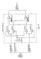
- the composite signal out of the amplifier channel 25A (FIG. 1) is, after passing through the second detector matrix 27, divided into two equal portions, with one such portion being applied to a gate S1 and the other such portion being applied to a gate D2.
- the composite signal out of the amplifier channel 25B is, after passing through the second detector matrix 27, divided into two equal portions, with one such portion being applied to a gate S2 and the other such portion being applied to a gate D1.
- Each one of the just-mentioned gates may be a conventional gated amplifier having an enabling terminal (not numbered).
- An enabling (or disabling) signal for each gate S1, S2, D1, D2 is derived, as shown, from a driver 271.
- driver may be a bistable multivibrator actuated by successively occurring signals from the controller 12 (FIG. 1).
- the normal output or such a multivibrator is connected to the enabling terminals of gates S1 and D1 land the complementary output is connected to the enabling terminals of gates S2 and D2.
- Gates S1 and S2 are connected to a summing amplifier 272 and gates D1 and D2 are connected to a summing amplifier 273.
- the signals out of the summing amplifier 272, 273 are connected to A/D converters 31 (FIG. 1).
- gates S1 and D1 are open and gates S2 and D2 are closed.
- the signal then extant at the output of amplifier channel 25A (say composite signal [S + (p + jy)]) when no phase imbalance exists, or composite signal [S + Se + (p + jy) + (p + jy)e] when an imbalance in amplitude exists, or composite signal [S+ + (p + jy+] when an imbalance in phase exists, or a vectorial sum of the latter two composite signals) is passed, via summing amplifier 272 to A/D converters 31 (FIG. 1).
- gate D1 is enabled to permit composite signal [S - (p + jy)], [S - Se - (p + jy) + (p + jy)e], [S ⁇ - (p + jy ⁇ ] or the vectorial sum of the latter two composite signals to be passed from amplifier channel 25B, via summing amplifier 273 to A/D converters 31 (FIG. 1).
- driver 271 changes state in response to the next following signal from the controller 12 (FIG. 1), gates S2 and D2 are opened and gates S1 and D1 are closed.
- the then extant output of amplifier channel 25A is passed, via gate D2 and summing amplifier 273, to A/D converters 31 and the then extant output of amplifier channel 25B is passed, via gate S2 and summing amplifier 272, to A/D converters 31 (FIG. 1).
- the switch matrix 29 just described may be used as the switch matrix 23 (FIG. 1).
- the composite signal [S + (p +1 jy)] out of the combiner 21 (FIG. 1) is applied to the gates S1 and D2 in place of composite signals derived from amplifier channel 25A;
- the composite signal [S-(p + jy)] is applied to the gates S2 and D1 in place of the composite signals derived from amplifier channel 25B;
- the output of the summing amplifier 272 is connected to the input of the amplifier channel 25A (FIG. 1) rather than to A/D converters 31; and
- the output of the summing amplifier 273 is connected to the input of the amplifier channel 25B (FIG. 1) rather than to A/D converters 31, then the desired switching of input signal to the amplifier channels 25A, 25B will be attained.
- the switch matrix 23 is not required if the phase of the reference signal is appropriately controlled during downconversion of the difference error signal (p + jy) R.F. in the first detector matrix 19′ (with matrix 19′ corresponding to first detector matrix 19 (FIG. 1)).
- the first detector matrix 19′ may include a mixer 51 and a mixer 53 to which the difference error signal (p + jy) R.F. and the monopulse sum signal S(R.F.) are applied as shown.
- a reference signal from a local oscillator (L.O. 55) is applied directly to the mixer 53.
- a reference signal from the L.O. 55 is applied, via a phase shifter 57, to the mixer 51.
- the phase shifter 57 is arranged so that, in response to control signals from a driver 59, the phase of the reference signal is either reversed, i.e., shifted by 180°, or is unaffected, i.e., shifted by 0°.
- the driver 59 in turn is actuated by successively occurring signals from the controller 12 (FIG. 1) that indicate the beginning of each successive interval.
- the mixer 53 is indicative of a monopulse sum signal at a selected I.F. frequency but that, during each interval between successively occuring signals from the controller 12 (FIG. 1), the output of the mixer 51 changes from + (p + jy) to -(p + jy).
- FFT 63 fast Fourier transform
- FFT 61 fast Fourier transform
- FFT 63 a fast Fourier transform
- 63 corresponding outputs of FFT 61, 63 are added and subtracted in a coherent ADD/SUBTRACT matrix 65.
- successive digital numbers are impressed on finite impulse filters (FIR 67, FIR 69) and corresponding outputs of such filters are added and subtracted in the coherent ADD/SUBTRACT matrix 65. In either case, any effect of imbalance is substantially eliminated from the outputs of the coherent ADD/SUBTRACT matrix 65.
- each input of the coherent ADD/SUBTRACT matrix 65 is multiplied (in multipliers 67, 69) by the complex conjugate of the sum signal S* out of such matrix and the output of the multiplier 69 is divided (in divider 71) by the output of the multiplier 67.
- integration in PDI 73 and PDI 75
- division in divider 77
- the magnitude of the sum signal is first found in either a "look up table” or by extracting, in element 81, square root of the product of the sum signal out of the coherent ADD/SUBTRACT matrix 65.
- the values of the monopulse pitch error, P, and the monopulse yaw error Y are then derived as shown by operation of multiplier 83 and dividers 85, 87.
- demultiplexing of the difference error signal i.e., separating the pitch, p, and yaw, jy, components of the difference error signal (p + jy) may be accomplished before conversion of the analog signals out of the switch matrix 29 (FIG. 1).
- the outputs out of the switch matrix 29 may be processed in a synchronous detector matrix (not shown) to effect the desired demultiplexing.
- the outputs of the switch matrix 29 would: (a) first be added together to produce a reference signal proportional to the monopulse sum signal, S; (b) the outputs of the switch matrix 29 would be subtracted one from the other to produce an angle error signal proportional to the difference error signal (p + jy); the angle error signal would be applied to each one of a pair of phase detectors; and the reference signal would be applied directly to one of the pair of phase detectors and, after having been shifted in phase by 90°, to the other one of the pair of phase detectors.
- the A/D converters 31 (FIG. 1) would then, of course, be modified to separately, but simultaneously, convert the sum signal S and the demultiplexed angle error signals. It will also be obvious that an analog integrator (not shown) could also be used in circuit before the A/D converters 31 (FIG. 1).
Landscapes
- Engineering & Computer Science (AREA)
- Radar, Positioning & Navigation (AREA)
- Remote Sensing (AREA)
- Computer Networks & Wireless Communication (AREA)
- Physics & Mathematics (AREA)
- General Physics & Mathematics (AREA)
- Signal Processing (AREA)
- Radar Systems Or Details Thereof (AREA)
Applications Claiming Priority (2)
| Application Number | Priority Date | Filing Date | Title |
|---|---|---|---|
| US07/382,971 US5014064A (en) | 1989-07-10 | 1989-07-10 | Monopulse tracking apparatus and method of operating same |
| US382971 | 1989-07-10 |
Publications (2)
| Publication Number | Publication Date |
|---|---|
| EP0408263A2 true EP0408263A2 (de) | 1991-01-16 |
| EP0408263A3 EP0408263A3 (en) | 1992-03-18 |
Family
ID=23511179
Family Applications (1)
| Application Number | Title | Priority Date | Filing Date |
|---|---|---|---|
| EP19900307409 Ceased EP0408263A3 (en) | 1989-07-10 | 1990-07-06 | Monopulse tracking apparatus and method of operating same |
Country Status (2)
| Country | Link |
|---|---|
| US (1) | US5014064A (de) |
| EP (1) | EP0408263A3 (de) |
Cited By (3)
| Publication number | Priority date | Publication date | Assignee | Title |
|---|---|---|---|---|
| EP0490578A1 (de) * | 1990-12-11 | 1992-06-17 | Raytheon Company | Radarsystem und -verfahren zum Betrieb desselben |
| CN103973624A (zh) * | 2014-04-28 | 2014-08-06 | 北京遥测技术研究所 | 一种星用Ka频段基于单脉冲0/π调制的接收通道 |
| US9121930B2 (en) | 2012-06-25 | 2015-09-01 | Autoliv Asp, Inc. | Two-channel monopulse radar for three-dimensional detection |
Families Citing this family (12)
| Publication number | Priority date | Publication date | Assignee | Title |
|---|---|---|---|---|
| US7417584B1 (en) * | 1989-11-08 | 2008-08-26 | Lockheed Martin Corporation | Monopulse radar estimation of target altitude at low angles of elevation |
| US5070336A (en) * | 1991-02-11 | 1991-12-03 | Hughes Aircraft Company | Radar guidance system correcting hardware induced channel-to-channel phase errors |
| ATE237811T1 (de) * | 1996-05-14 | 2003-05-15 | Honeywell Int Inc | Autonomes landeführungssystem |
| US5808578A (en) * | 1996-12-20 | 1998-09-15 | Barbella; Peter F. | Guided missile calibration method |
| US6018311A (en) * | 1998-07-14 | 2000-01-25 | Raytheon Company | Noncoherent gain enhancement technique for improved detection-estimation performance |
| RU2249232C2 (ru) * | 2003-04-15 | 2005-03-27 | Открытое акционерное общество "Корпорация "Фазотрон-Научно-исследовательский институт радиостроения" (ОАО "Корпорация "Фазотрон-НИИР") | Способ сопровождения радиоконтрастного объекта по направлению и устройство сопровождения радиоконтрастного объекта по направлению |
| RU2273863C1 (ru) * | 2004-10-20 | 2006-04-10 | Открытое акционерное общество "Корпорация "Фазотрон - научно-исследовательский институт радиостроения" | Моноимпульсное радиолокационное устройство сопровождения по направлению |
| RU2296349C9 (ru) * | 2005-02-14 | 2007-06-27 | Открытое акционерное общество "Корпорация "Фазотрон-Научно-исследовательский институт радиостроения" | Способ обнаружения и анализа радиосигналов |
| US8274425B2 (en) * | 2010-12-29 | 2012-09-25 | Raytheon Company | Single channel semi-active radar seeker |
| US8803731B2 (en) | 2011-03-30 | 2014-08-12 | Raytheon Company | Target-tracking radar and method for responding to fluctuations in target SNR |
| US8816895B2 (en) | 2011-04-15 | 2014-08-26 | Raytheon Company | Target-tracking radar classifier with glint detection and method for target classification using measured target epsilon and target glint information |
| FR3030774B1 (fr) * | 2014-12-19 | 2017-01-20 | Thales Sa | Procede de determination de parametres d'un filtre de compression et radar multivoies associe |
Family Cites Families (4)
| Publication number | Priority date | Publication date | Assignee | Title |
|---|---|---|---|---|
| GB1605311A (en) * | 1972-10-17 | 1989-07-19 | Marconi Co Ltd | Improvements in or relating to static split tracking radar systems |
| GB1562143A (en) * | 1977-03-07 | 1980-03-05 | Standard Telephones Cables Ltd | Height finding radar |
| FR2509475A2 (fr) * | 1977-06-03 | 1983-01-14 | Labo Cent Telecommunicat | Dispositif de poursuite angulaire precise d'un objectif radar |
| US4652882A (en) * | 1982-09-30 | 1987-03-24 | Raytheon Company | Receiver with wide dynamic range |
-
1989
- 1989-07-10 US US07/382,971 patent/US5014064A/en not_active Expired - Lifetime
-
1990
- 1990-07-06 EP EP19900307409 patent/EP0408263A3/en not_active Ceased
Cited By (3)
| Publication number | Priority date | Publication date | Assignee | Title |
|---|---|---|---|---|
| EP0490578A1 (de) * | 1990-12-11 | 1992-06-17 | Raytheon Company | Radarsystem und -verfahren zum Betrieb desselben |
| US9121930B2 (en) | 2012-06-25 | 2015-09-01 | Autoliv Asp, Inc. | Two-channel monopulse radar for three-dimensional detection |
| CN103973624A (zh) * | 2014-04-28 | 2014-08-06 | 北京遥测技术研究所 | 一种星用Ka频段基于单脉冲0/π调制的接收通道 |
Also Published As
| Publication number | Publication date |
|---|---|
| US5014064A (en) | 1991-05-07 |
| EP0408263A3 (en) | 1992-03-18 |
Similar Documents
| Publication | Publication Date | Title |
|---|---|---|
| US5014064A (en) | Monopulse tracking apparatus and method of operating same | |
| US5059968A (en) | Radar system and method of operating such system | |
| US4584710A (en) | Coherent receiver phase and amplitude alignment circuit | |
| EP0082427B1 (de) | Nach zwei Messverfahren betriebener Radarempfänger | |
| US2964622A (en) | Image suppressed superheterodyne receiver | |
| US5894496A (en) | Method and apparatus for detecting and compensating for undesired phase shift in a radio transceiver | |
| US5150128A (en) | In-phase and quadrature conversion error compensator | |
| US4849764A (en) | Interference source noise cancelling beamformer | |
| US3881177A (en) | Frequency agile-baseband sidelobe canceller | |
| US3339199A (en) | Single-channel signal-processing network and monopulse receiver systems embodying the same | |
| US4220953A (en) | Circuit arrangement for improving accuracy of angular measurements in radar systems | |
| US4152702A (en) | Adaptive antenna lobing on spread spectrum signals at negative S/N | |
| CA2047813C (en) | Acceleration compensation by matched filtering | |
| US3713155A (en) | Monopulse radar receiver | |
| US4219816A (en) | Method of and apparatus for angular measurement in target tracking radar systems | |
| US4060806A (en) | Phased array radars | |
| US3778829A (en) | Guarded monopulse radar system | |
| US4489327A (en) | Direction finding | |
| US5281973A (en) | Local oscillator frequency control means for semiactive missile guidance and control system | |
| US4062011A (en) | MTI System processor and method | |
| US4143372A (en) | Side-lobe blanking arrangement for a radar system | |
| CN115097501A (zh) | 基于双天线处理通道的卫星导航信号的数据处理方法及装置 | |
| US5402130A (en) | Monopulse processor | |
| US4847860A (en) | Phase-control system for telecommunications signals received by an adaptive antenna | |
| US3064254A (en) | Monopulse radar with linear error voltage |
Legal Events
| Date | Code | Title | Description |
|---|---|---|---|
| PUAI | Public reference made under article 153(3) epc to a published international application that has entered the european phase |
Free format text: ORIGINAL CODE: 0009012 |
|
| AK | Designated contracting states |
Kind code of ref document: A2 Designated state(s): DE FR GB |
|
| PUAL | Search report despatched |
Free format text: ORIGINAL CODE: 0009013 |
|
| AK | Designated contracting states |
Kind code of ref document: A3 Designated state(s): DE FR GB |
|
| 17P | Request for examination filed |
Effective date: 19920904 |
|
| 17Q | First examination report despatched |
Effective date: 19940629 |
|
| STAA | Information on the status of an ep patent application or granted ep patent |
Free format text: STATUS: THE APPLICATION HAS BEEN REFUSED |
|
| 18R | Application refused |
Effective date: 19950912 |