EP0408325A1 - Agitateur catalytique pour modifier des atmosphères de four - Google Patents
Agitateur catalytique pour modifier des atmosphères de four Download PDFInfo
- Publication number
- EP0408325A1 EP0408325A1 EP90307559A EP90307559A EP0408325A1 EP 0408325 A1 EP0408325 A1 EP 0408325A1 EP 90307559 A EP90307559 A EP 90307559A EP 90307559 A EP90307559 A EP 90307559A EP 0408325 A1 EP0408325 A1 EP 0408325A1
- Authority
- EP
- European Patent Office
- Prior art keywords
- furnace
- vanes
- atmosphere
- shaft
- agitator
- Prior art date
- Legal status (The legal status is an assumption and is not a legal conclusion. Google has not performed a legal analysis and makes no representation as to the accuracy of the status listed.)
- Granted
Links
- 230000003197 catalytic effect Effects 0.000 title claims description 5
- 230000004048 modification Effects 0.000 title description 4
- 238000012986 modification Methods 0.000 title description 4
- 239000007789 gas Substances 0.000 claims abstract description 52
- 239000003054 catalyst Substances 0.000 claims abstract description 26
- 239000000654 additive Substances 0.000 claims abstract description 23
- 230000000996 additive effect Effects 0.000 claims abstract description 23
- 238000010438 heat treatment Methods 0.000 claims description 9
- 238000002407 reforming Methods 0.000 claims description 5
- 239000000470 constituent Substances 0.000 description 7
- 239000007788 liquid Substances 0.000 description 5
- 238000006243 chemical reaction Methods 0.000 description 4
- OKTJSMMVPCPJKN-UHFFFAOYSA-N Carbon Chemical compound [C] OKTJSMMVPCPJKN-UHFFFAOYSA-N 0.000 description 3
- 229910052799 carbon Inorganic materials 0.000 description 3
- 239000003795 chemical substances by application Substances 0.000 description 3
- VNWKTOKETHGBQD-UHFFFAOYSA-N methane Chemical compound C VNWKTOKETHGBQD-UHFFFAOYSA-N 0.000 description 3
- 239000000203 mixture Substances 0.000 description 3
- 229910000831 Steel Inorganic materials 0.000 description 1
- 230000005540 biological transmission Effects 0.000 description 1
- 239000001273 butane Substances 0.000 description 1
- 229910001026 inconel Inorganic materials 0.000 description 1
- 239000012212 insulator Substances 0.000 description 1
- 238000000034 method Methods 0.000 description 1
- IJDNQMDRQITEOD-UHFFFAOYSA-N n-butane Chemical compound CCCC IJDNQMDRQITEOD-UHFFFAOYSA-N 0.000 description 1
- OFBQJSOFQDEBGM-UHFFFAOYSA-N n-pentane Natural products CCCCC OFBQJSOFQDEBGM-UHFFFAOYSA-N 0.000 description 1
- 230000001681 protective effect Effects 0.000 description 1
- 230000036632 reaction speed Effects 0.000 description 1
- 230000000717 retained effect Effects 0.000 description 1
- 239000010959 steel Substances 0.000 description 1
- 239000000126 substance Substances 0.000 description 1
Images
Classifications
-
- F—MECHANICAL ENGINEERING; LIGHTING; HEATING; WEAPONS; BLASTING
- F27—FURNACES; KILNS; OVENS; RETORTS
- F27B—FURNACES, KILNS, OVENS OR RETORTS IN GENERAL; OPEN SINTERING OR LIKE APPARATUS
- F27B5/00—Muffle furnaces; Retort furnaces; Other furnaces in which the charge is held completely isolated
- F27B5/06—Details, accessories or equipment specially adapted for furnaces of these types
- F27B5/16—Arrangements of air or gas supply devices
-
- C—CHEMISTRY; METALLURGY
- C21—METALLURGY OF IRON
- C21D—MODIFYING THE PHYSICAL STRUCTURE OF FERROUS METALS; GENERAL DEVICES FOR HEAT TREATMENT OF FERROUS OR NON-FERROUS METALS OR ALLOYS; MAKING METAL MALLEABLE, e.g. BY DECARBURISATION OR TEMPERING
- C21D1/00—General methods or devices for heat treatment, e.g. annealing, hardening, quenching or tempering
- C21D1/74—Methods of treatment in inert gas, controlled atmosphere, vacuum or pulverulent material
- C21D1/76—Adjusting the composition of the atmosphere
- C21D1/763—Adjusting the composition of the atmosphere using a catalyst
-
- C—CHEMISTRY; METALLURGY
- C21—METALLURGY OF IRON
- C21D—MODIFYING THE PHYSICAL STRUCTURE OF FERROUS METALS; GENERAL DEVICES FOR HEAT TREATMENT OF FERROUS OR NON-FERROUS METALS OR ALLOYS; MAKING METAL MALLEABLE, e.g. BY DECARBURISATION OR TEMPERING
- C21D1/00—General methods or devices for heat treatment, e.g. annealing, hardening, quenching or tempering
- C21D1/74—Methods of treatment in inert gas, controlled atmosphere, vacuum or pulverulent material
- C21D1/767—Methods of treatment in inert gas, controlled atmosphere, vacuum or pulverulent material with forced gas circulation; Reheating thereof
-
- F—MECHANICAL ENGINEERING; LIGHTING; HEATING; WEAPONS; BLASTING
- F27—FURNACES; KILNS; OVENS; RETORTS
- F27D—DETAILS OR ACCESSORIES OF FURNACES, KILNS, OVENS OR RETORTS, IN SO FAR AS THEY ARE OF KINDS OCCURRING IN MORE THAN ONE KIND OF FURNACE
- F27D7/00—Forming, maintaining or circulating atmospheres in heating chambers
- F27D7/04—Circulating atmospheres by mechanical means
-
- F—MECHANICAL ENGINEERING; LIGHTING; HEATING; WEAPONS; BLASTING
- F27—FURNACES; KILNS; OVENS; RETORTS
- F27B—FURNACES, KILNS, OVENS OR RETORTS IN GENERAL; OPEN SINTERING OR LIKE APPARATUS
- F27B5/00—Muffle furnaces; Retort furnaces; Other furnaces in which the charge is held completely isolated
- F27B5/06—Details, accessories or equipment specially adapted for furnaces of these types
- F27B5/16—Arrangements of air or gas supply devices
- F27B2005/166—Means to circulate the atmosphere
- F27B2005/167—Means to circulate the atmosphere the atmosphere being recirculated through the treatment chamber by a turbine
Definitions
- the present invention relates to agitator means for use in a continuous atmosphere furnace for the modification of the specific atmosphere.
- the invention is of particular use in a continuous atmosphere furnace employed for the heat treatment of metallic articles.
- the modification of a furnace atmosphere to give a desired composition has generally been effected by mixing an additive gas into the furnace atmosphere.
- the additive gas is introduced into the furnace alone or together with the furnace atmosphere, and modifies the furnace atmosphere by reaction with the atmosphere and by the incidental inter-reaction of furnace atmosphere gas constituents, but only when the additive gas is heated and mixed well with the furnace atmosphere.
- the additive gas, with or without the atmosphere gas is not properly introduced into the furnace, such as without due consideration of its relation with articles to be treated in the furnace, the atmosphere will come into contact with the articles before it has been modified substantially completely. Poor modification of the atmosphere gases can often result in poor or inadequate heat treatment of the articles in the furnace.
- US-A-4,294,436 discloses a furnace for the heat-treatment of metallic articles with a protective atmosphere, wherein fans are used to agitate the raw gases radially before they make contact with the metallic articles.
- fans are used to agitate the raw gases radially before they make contact with the metallic articles.
- a substantial part of the raw gases supplied into the furnace disadvantageously make contact with the articles to be heat-treated before they make contact with the catalytic and heating means intended to modify them into the desired composition.
- Japanese Preliminary Patent Publication No. 54-64633 discloses a carburising furnace, into which liquid atmosphere constituents are supplied dropwise.
- a gas agitator is rotated within a space, lateral sides of which are encircled by wire gauze containing a catalyst, the bottom being closed by the upper plate of a muffle.
- this muffle prevents the liquid atmosphere constituents droping directly onto the article to be heat-treated, it also disadvantageously prevents the furnace atmosphere entering upwardly into the agitator space. Thus, it cannot be expected that the liquid atmosphere constituents fed dropwise into the space will be adequately mixed there with the furnace atmosphere and reacted by the gas agitator.
- the gas agitator effectively acts primarily as an atomiser which is vigorously rotated so as to atomise the liquid atmosphere constituents, radially and forcibly dispersing them as they are dropped into the agitator space, and does not really act as an agitator.
- a further disadvantage of this carburising furnace is that, since a dropper pipe must be provided which opens between the circular catalyst surrounding the agitator and adjacent to the rotary path of the agitator vanes, to allow the liquid atmosphere drops to be atomised instantaneously by the wind current of the agitator, it is impossible to locate the circular catalyst very close to the agitator, with the interposition of the dropper.
- a constant atmosphere furnace provided with an atmosphere agitator, the agitator comprising a shaft rotatably mounted in an exposed portion of the furnace, preferably through an upper wall, the shaft being provided with vanes adapted to create a negative pressure in the vicinity of their centre when the shaft is rotated, supply means being located, preferably within said shaft, to provide additive gases to the vicinity of the centre of the vanes, and wherein gases brought into said vicinity are expelled radially, in operation, by the action of the vanes through a catalyst.
- the catalyst is preferably located in a permeable structure in the form of a cylinder located as close as practically possible to the vanes.
- An advantage is that there is no supply line between the catalyst and vanes, thus ensuring that the maximum possible amount of gas goes through the catalyst, so that there is effectively no unreacted gas in the furnace atmosphere.
- the present invention provides a catalytic agitator for reforming a furnace atmosphere in a continuous atmosphere heating furnace, having a shaft rotatively mounted to a desired location of an upper wall of the furnace and extending substantially at a right angle with said upper wall and having a plurality of vanes fitted to a free end of said shaft which is exposed within the furnace; it is characterised that said vanes are shaped so as to produce a negative pressure at and about the centre of rotation when they are rotated, whereby to suck a furnace atmosphere toward the centre and to eject the thus sucked furnace atmosphere toward radial directions and outwardly substantially at a right angle with the shaft vanes, that the shaft is provided with a supply opening for feeding an additive gas toward the centre of rotation of the vanes, and that there is provided a cage containing catalysts, the cage being annular as a whole with a bottom opened and being located closely to an outer locus of the rotation of the vanes and without anything intervening between the catalyst cage and the vanes.
- the catalysts are preferably operable at a comparatively low temperature.
- a catalytic agitator for reforming a furnace atmosphere in a continuous heat treatment furnace rotary vanes of which induce the furnace atmosphere toward the centre of rotation of the vanes, due to a negative pressure produced by the rotation of vanes.
- Additive gas for reforming the atmosphere is also introduced to said centre.
- the atmosphere and additive gases are mixed to each other at once when the additive gas is introduced into the furnace, and radially ejected to contact with an annular catalyst agent.
- the annular inner surface of catalyst agent is located closely to rotary locus of the vanes, so that the mixed atmosphere and additive gases can contact with the catalyst without any intervention therebetween.
- the catalyst agent has no bottom so that the furnace atmosphere is freely induced to the centre of rotation of vanes, on account of the aforementioned negative pressure exerting at and about said centre.
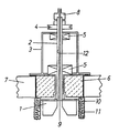
- the drawing shows an explanatory cross sectional view of a furnace atmosphere modifying agitator in accordance with the present invention, the lower part of the drawing being within a continuous atmosphere furnace, downwardly from and upwardly to which a furnace atmosphere is sucked by the rotation of vanes 1 of the agitator means.
- the furnace atmosphere sucked up is flung out by the rotating vanes in a direotion transverse to a rotary shaft 2 of the agitator means.
- said mesh cage has a bottom-opened annular shape, the inner annular surface of which is extremely closely located to a rotary radius of the vanes 1, and the axis of which is coaxial with the rotary shaft 2.
- the illustrated agitator works as follows.
- the mixing of the gases by such a process is very effective for thoroughly mixing them. It is additionally advantageous for the amount of additive gas to be kept small, compared to an amount of the furnace atmosphere sucked to the centre of the rotation of vanes 1, so that the mixed gas scarcely suffers from a lowering of temperature, and so their reaction speed is consequently quick.
- the furnace atmosphere and the additive gas thus mixed together pass through a catalyst 11, whereby their reaction is accelerated to produce a gas atmosphere of a desired composition.
- This gas then circulates within the furnace to perform a predetermined heat treatment.
- the drawing shows an agitator made in accordance with this invention, which is employed in reforming a furnace atmosphere in a gas carburising furnace.
- the vanes are made of heat-resistant steel, meshed gauges 10 are made of inconel wires, and catalysts 11 work at a comparatively low temperature such as 900-940°C, corresponding to a carburising temperature.
- the outer diameter of rotation of the vanes 1 is about 400mm, their heights are about 200mm, and rotary velocity 1,200rpm.
- the gas transmission of the catalysts 11 contained in the wire meshes 10 was about 50%.
- a furnace atmosphere for carburising an endothermic gas (consisting of CO, H2, CO2, H2O, CH4, N2) made by the conversion of butane gas was employed, while the additive gas was a city gas, the principle constituent of which is methane.
- Amounts of CO and CO2 of the furnace atmosphere were measured by infrared analysis to establish the carbon concentration thereof, while the temperature was also measured. Control of the additive gas was automated according to the concentration and temperature. More specifically, the amount of furnace atmosphere was 10m3/h, additive gas was 0-0,04m3/h, temperature was 910°C, and carbon concentration was constant at 7.9%.
- 3 is a frame, 4 pulley, 5 bearings, 6 insulators and 7 a part of upper furnace wall.
Landscapes
- Engineering & Computer Science (AREA)
- Chemical & Material Sciences (AREA)
- Mechanical Engineering (AREA)
- Thermal Sciences (AREA)
- Physics & Mathematics (AREA)
- Crystallography & Structural Chemistry (AREA)
- Materials Engineering (AREA)
- Metallurgy (AREA)
- Organic Chemistry (AREA)
- General Engineering & Computer Science (AREA)
- Chemical Kinetics & Catalysis (AREA)
- Solid-Phase Diffusion Into Metallic Material Surfaces (AREA)
- Furnace Details (AREA)
Applications Claiming Priority (2)
| Application Number | Priority Date | Filing Date | Title |
|---|---|---|---|
| JP80875/89U | 1989-07-10 | ||
| JP1989080875U JPH057237Y2 (fr) | 1989-07-10 | 1989-07-10 |
Publications (2)
| Publication Number | Publication Date |
|---|---|
| EP0408325A1 true EP0408325A1 (fr) | 1991-01-16 |
| EP0408325B1 EP0408325B1 (fr) | 1994-11-09 |
Family
ID=13730521
Family Applications (1)
| Application Number | Title | Priority Date | Filing Date |
|---|---|---|---|
| EP90307559A Expired - Lifetime EP0408325B1 (fr) | 1989-07-10 | 1990-07-10 | Agitateur catalytique pour modifier des atmosphères de four |
Country Status (5)
| Country | Link |
|---|---|
| US (1) | US5098070A (fr) |
| EP (1) | EP0408325B1 (fr) |
| JP (1) | JPH057237Y2 (fr) |
| CN (1) | CN1021462C (fr) |
| DE (1) | DE69013997T2 (fr) |
Families Citing this family (4)
| Publication number | Priority date | Publication date | Assignee | Title |
|---|---|---|---|---|
| US5426157A (en) * | 1994-03-16 | 1995-06-20 | Air Products And Chemicals, Inc. | Flexibilized polyepoxide resins incorporating poly-N-methylated secondary amines |
| DE102008029001B3 (de) * | 2008-06-20 | 2009-09-17 | Ipsen International Gmbh | Verfahren und Einrichtung zur Wärmebehandlung von metallischen Werkstoffen |
| CN111362772B (zh) * | 2020-02-13 | 2022-10-04 | 东营威联化学有限公司 | 一种利用直馏石脑油法生产二甲苯的装置 |
| KR20230085383A (ko) * | 2021-12-07 | 2023-06-14 | 주식회사 케이티앤지 | 라이오셀 토우를 포함하는 담배 필터 |
Citations (1)
| Publication number | Priority date | Publication date | Assignee | Title |
|---|---|---|---|---|
| US4294436A (en) * | 1979-09-05 | 1981-10-13 | Kanto Yakin Kogyo Kabushiki Kaisha | Furnace with protective atmosphere for heating metals |
Family Cites Families (2)
| Publication number | Priority date | Publication date | Assignee | Title |
|---|---|---|---|---|
| DE1049888B (de) * | 1959-02-05 | Dr. Schmitz -&. Apelt, Wuppertal-Langerfeld | Einrichtung zur Warmbehandlung von Werkstücken mit chemisch wirksamen Gasen, insbesondere Aufkohlungsofen | |
| JPS59162941A (ja) * | 1983-03-08 | 1984-09-13 | Chugai Ro Kogyo Kaisha Ltd | 炉内設置型吸熱型ガス発生装置 |
-
1989
- 1989-07-10 JP JP1989080875U patent/JPH057237Y2/ja not_active Expired - Lifetime
- 1989-10-25 CN CN89108153.4A patent/CN1021462C/zh not_active Expired - Lifetime
-
1990
- 1990-07-02 US US07/546,926 patent/US5098070A/en not_active Expired - Lifetime
- 1990-07-10 EP EP90307559A patent/EP0408325B1/fr not_active Expired - Lifetime
- 1990-07-10 DE DE69013997T patent/DE69013997T2/de not_active Expired - Fee Related
Patent Citations (1)
| Publication number | Priority date | Publication date | Assignee | Title |
|---|---|---|---|---|
| US4294436A (en) * | 1979-09-05 | 1981-10-13 | Kanto Yakin Kogyo Kabushiki Kaisha | Furnace with protective atmosphere for heating metals |
Non-Patent Citations (4)
| Title |
|---|
| PATENT ABSTRACTS OF JAPAN, vol. 11, no. 357 (C-458)[2804], 20th November 1987; & JP-A-62 130 271 (TOKYO NETSUSHIYORI KOGYO) 12-06-1987 * |
| PATENT ABSTRACTS OF JAPAN, vol. 11, no. 371 (C-462)[2818], 3rd December 1987; & JP-A-62 146 220 (TOKYO NETSUSHIYORI KOGYO) 30-06-1987 * |
| PATENT ABSTRACTS OF JAPAN, vol. 9, no. 211 (C-300)[1934], 29th August 1985; & JP-A-60 75 516 (TOUYOU ROKOUGIYOU) 27-04-1985 * |
| SOVIET INVENTIONS ILLUSTRATED, week E32, 22nd September 1982, class M, page 24, abstract no. 67434 E/32, Derwent Publications Ltd, London, GB; & SU-A-865 935 (THERMOTECH METALLUR) 23-09-1981 * |
Also Published As
| Publication number | Publication date |
|---|---|
| JPH0322051U (fr) | 1991-03-06 |
| DE69013997T2 (de) | 1995-05-24 |
| JPH057237Y2 (fr) | 1993-02-24 |
| DE69013997D1 (de) | 1994-12-15 |
| CN1021462C (zh) | 1993-06-30 |
| CN1048728A (zh) | 1991-01-23 |
| US5098070A (en) | 1992-03-24 |
| EP0408325B1 (fr) | 1994-11-09 |
Similar Documents
| Publication | Publication Date | Title |
|---|---|---|
| US5137566A (en) | Process for preheating iron-containing reactor feed prior to being treated in a fluidized bed reactor | |
| US8333852B2 (en) | Method for conditioning process gases for the heat treatment of metallic work pieces in industrial furnaces | |
| JP2003193152A (ja) | モリブデン金属及びそれらの製造 | |
| US3278295A (en) | Method of stirring dispersing or homogenizing metal or slag charges having a temperature of at least 800deg. c. | |
| EP0408325B1 (fr) | Agitateur catalytique pour modifier des atmosphères de four | |
| US3545962A (en) | Process for the gaseous deoxidation of anode copper | |
| CA1302683C (fr) | Methode de traitement de liquide ou methode utilisant un produit liquide | |
| US2252714A (en) | Process and apparatus for making metal powder | |
| US2079404A (en) | Catalyst preparation | |
| US20040067190A1 (en) | Molybdenum carbide | |
| US5194228A (en) | Fluidized bed apparatus for chemically treating workpieces | |
| US4871516A (en) | Apparatus and method for conducting chemical reactions | |
| GB2211860A (en) | Producing reformed gas for direct reduction of metal oxides to iron | |
| US3028226A (en) | Apparatus for providing uniform descent of a particulate solid material disposed in a reaction chamber | |
| JPS6127964Y2 (fr) | ||
| US852440A (en) | Process of reducing zinc ores. | |
| US2809096A (en) | Process for generating sodium monoxide | |
| GB777325A (en) | Process and apparatus for the production of synthesis gas comprising hydrogen and carbon monoxide | |
| USRE27548E (en) | Spitz etal method op repining copper | |
| JPS5629666A (en) | Chemical deposition apparatus | |
| Habersberger | Application of thermal analysis to the investigation of catalysts | |
| JPH02115295A (ja) | 反応装置 | |
| US1177396A (en) | Desulfurizing method for treating refractory ores. | |
| JPS5569210A (en) | Shaft type reducing furnace | |
| GB1064164A (en) | Improvements in and relating to polymerization processes |
Legal Events
| Date | Code | Title | Description |
|---|---|---|---|
| PUAI | Public reference made under article 153(3) epc to a published international application that has entered the european phase |
Free format text: ORIGINAL CODE: 0009012 |
|
| AK | Designated contracting states |
Kind code of ref document: A1 Designated state(s): DE FR GB |
|
| 17P | Request for examination filed |
Effective date: 19910312 |
|
| 17Q | First examination report despatched |
Effective date: 19921223 |
|
| GRAA | (expected) grant |
Free format text: ORIGINAL CODE: 0009210 |
|
| AK | Designated contracting states |
Kind code of ref document: B1 Designated state(s): DE FR GB |
|
| REF | Corresponds to: |
Ref document number: 69013997 Country of ref document: DE Date of ref document: 19941215 |
|
| ET | Fr: translation filed | ||
| PLBE | No opposition filed within time limit |
Free format text: ORIGINAL CODE: 0009261 |
|
| STAA | Information on the status of an ep patent application or granted ep patent |
Free format text: STATUS: NO OPPOSITION FILED WITHIN TIME LIMIT |
|
| 26N | No opposition filed | ||
| REG | Reference to a national code |
Ref country code: GB Ref legal event code: IF02 |
|
| PGFP | Annual fee paid to national office [announced via postgrant information from national office to epo] |
Ref country code: DE Payment date: 20080717 Year of fee payment: 19 |
|
| PGFP | Annual fee paid to national office [announced via postgrant information from national office to epo] |
Ref country code: FR Payment date: 20080718 Year of fee payment: 19 |
|
| PGFP | Annual fee paid to national office [announced via postgrant information from national office to epo] |
Ref country code: GB Payment date: 20080716 Year of fee payment: 19 |
|
| GBPC | Gb: european patent ceased through non-payment of renewal fee |
Effective date: 20090710 |
|
| REG | Reference to a national code |
Ref country code: FR Ref legal event code: ST Effective date: 20100331 |
|
| PG25 | Lapsed in a contracting state [announced via postgrant information from national office to epo] |
Ref country code: FR Free format text: LAPSE BECAUSE OF NON-PAYMENT OF DUE FEES Effective date: 20090731 |
|
| PG25 | Lapsed in a contracting state [announced via postgrant information from national office to epo] |
Ref country code: GB Free format text: LAPSE BECAUSE OF NON-PAYMENT OF DUE FEES Effective date: 20090710 |
|
| PG25 | Lapsed in a contracting state [announced via postgrant information from national office to epo] |
Ref country code: DE Free format text: LAPSE BECAUSE OF NON-PAYMENT OF DUE FEES Effective date: 20100202 |