EP0408355A2 - Débimètres à tourbillons - Google Patents
Débimètres à tourbillons Download PDFInfo
- Publication number
- EP0408355A2 EP0408355A2 EP90307615A EP90307615A EP0408355A2 EP 0408355 A2 EP0408355 A2 EP 0408355A2 EP 90307615 A EP90307615 A EP 90307615A EP 90307615 A EP90307615 A EP 90307615A EP 0408355 A2 EP0408355 A2 EP 0408355A2
- Authority
- EP
- European Patent Office
- Prior art keywords
- cylinder
- flowmeter
- upstream
- fluid
- gap
- Prior art date
- Legal status (The legal status is an assumption and is not a legal conclusion. Google has not performed a legal analysis and makes no representation as to the accuracy of the status listed.)
- Granted
Links
- 238000011144 upstream manufacturing Methods 0.000 claims abstract description 22
- 230000001939 inductive effect Effects 0.000 claims abstract description 3
- 239000012530 fluid Substances 0.000 claims description 22
- 238000007664 blowing Methods 0.000 description 3
- 238000001514 detection method Methods 0.000 description 3
- 238000005259 measurement Methods 0.000 description 3
- 238000000034 method Methods 0.000 description 3
- 230000008569 process Effects 0.000 description 2
- 230000008901 benefit Effects 0.000 description 1
- 230000008878 coupling Effects 0.000 description 1
- 238000010168 coupling process Methods 0.000 description 1
- 238000005859 coupling reaction Methods 0.000 description 1
- 230000003628 erosive effect Effects 0.000 description 1
- 238000002474 experimental method Methods 0.000 description 1
- 239000000835 fiber Substances 0.000 description 1
- 238000011835 investigation Methods 0.000 description 1
- 238000004519 manufacturing process Methods 0.000 description 1
- 238000012986 modification Methods 0.000 description 1
- 230000004048 modification Effects 0.000 description 1
- 230000003287 optical effect Effects 0.000 description 1
- 230000010355 oscillation Effects 0.000 description 1
- 230000000737 periodic effect Effects 0.000 description 1
- 238000012545 processing Methods 0.000 description 1
- 239000000126 substance Substances 0.000 description 1
- 238000012546 transfer Methods 0.000 description 1
- 238000012800 visualization Methods 0.000 description 1
Images
Classifications
-
- G—PHYSICS
- G01—MEASURING; TESTING
- G01F—MEASURING VOLUME, VOLUME FLOW, MASS FLOW OR LIQUID LEVEL; METERING BY VOLUME
- G01F1/00—Measuring the volume flow or mass flow of fluid or fluent solid material wherein the fluid passes through a meter in a continuous flow
- G01F1/05—Measuring the volume flow or mass flow of fluid or fluent solid material wherein the fluid passes through a meter in a continuous flow by using mechanical effects
- G01F1/20—Measuring the volume flow or mass flow of fluid or fluent solid material wherein the fluid passes through a meter in a continuous flow by using mechanical effects by detection of dynamic effects of the flow
- G01F1/32—Measuring the volume flow or mass flow of fluid or fluent solid material wherein the fluid passes through a meter in a continuous flow by using mechanical effects by detection of dynamic effects of the flow using swirl flowmeters
- G01F1/3209—Measuring the volume flow or mass flow of fluid or fluent solid material wherein the fluid passes through a meter in a continuous flow by using mechanical effects by detection of dynamic effects of the flow using swirl flowmeters using Karman vortices
- G01F1/3218—Measuring the volume flow or mass flow of fluid or fluent solid material wherein the fluid passes through a meter in a continuous flow by using mechanical effects by detection of dynamic effects of the flow using swirl flowmeters using Karman vortices bluff body design
Definitions
- This invention relates to flowmeters of the vortex shedding variety.
- the invention relates to a bluff body vortex generator for use in such flowmeters and which is designed to improve the repeatability and accuracy of the flowmeter.
- the principle of the vortex shedding phenomenon in its application to measurement of the flow rate in a channel or a pipe is that the vortex shedding frequency is proportional to the flow velocity near the body which is the cause of the vortex shedding.
- a vortex shedding flowmeter comprises a passage through which the fluid to be measured can flow, an obstacle (ie the bluff body) capable of generating fluid vortices, and a sensing means for indicating the rate of flow.
- the purpose of the bluff body is to generate strong, stable fluid vortices which can be differentiated from factors such as random velocity fluctuations due to turbulence, which factors tend to degrade the signal.
- the production of a strong flow-related signal assists in alleviating problems in the processing of signals received from transducers used to detect the vortex shedding.
- the method described in the paper for detecting vortex shedding used a sensor placed entirely outside the process fluid, thereby making the system more robust and improving the performance of the flowmeter.
- cylinder means a body having a cross-sectional area of any shape which is substantially uniform along its longitudinal axis.
- a flowmeter for measuring the rate of flow of a fluid
- the flowmeter comprising: a flow tube forming a passage for the fluid to be measured; a bluff body disposed in the flow tube for inducing vortices in the flowing fluid, the bluff body comprising a first, upstream, cylinder having an arcuate front surface and a planar rear surface, and a second, downstream, cylinder having a planar front surface and a planar or concave rear surface, the two cylinders being separated at their adjacent surfaces by a gap whose width is up to fifty per cent of the diameter of the upstream cylinder; and a sensing means for measuring the frequency of the vortices shed by the bluff body.
- a suitable sensing means may incorporate moving parts such as flags, cantilevers or diaphragms capable of responding to the fluid velocity or pressure.
- a stationary sensor such as a fixed plate with a strain gauge, or an optical sensor incorporating fibre optics, or an ultrasonic sensor, or a thermal detector, may be employed.
- said upstream cylinder may take the form of a semi-circular cylinder.
- said upstream cylinder may take the form of a semi-ellipsoidal cylinder.
- the trailing edges of said upstream cylinder comprise sharp edges.
- said gap separating the two cylinders has parallel walls to allow a piston-like movement of the fluid from one side to the other as shedding occurs.
- the front edges of said trailing cylinder are slightly rounded, to facilitate fluid flow from the gap.
- edges are the most exposed part of the bluff body, is that rounded edges will be much more resistant to erosion by the fluid.
- this part of the bluff body is the best location for a sensor to detect the vortex shedding frequency, using perhaps a heat transfer or pressure sensor.
- the rear edges of said trailing cylinder are left sharp. During the flowing period, the fluid moving towards the edge is separated from the edge and immediately starts to form a new vortex.
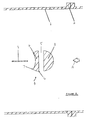
- Figure 1 shows a sectional view of a vortex flowmeter which comprises a flow tube 1 provided with end flanges 2 to facilitate coupling to the channel or pipe through which the fluid to be measured flows: the fluid flows through the flowmeter in the direction of the arrow A.
- the flowmeter comprises a bluff body vortex generator 9 positioned perpendicularly to the central flow axis of the flow tube 1, and consisting of two cylinders, an upstream cylinder 3 in the form of a semi-circular cylinder, and a downstream cylinder 4 in the form of a part of a semi-circular cylinder with a concave rear surface.
- the two cylinders are separated at their planar surfaces by a gap 5 which is twenty-five per cent of the diameter of the upstream cylinder.
- the two cylinders 3, 4 can be regarded as a near circular section cylinder which has been split across its diameter and then separated by the gap 5.
- the front edges 6 of the downstream cylinder are slightly rounded with a radius of four per cent of the diameter of the upstream cylinder.
- the rear edges 7 of the downstream cylinder are sharp with a radius of one per cent of the diameter of the upstream cylinder.
- the boundary layer separates behind the gap 5 at the sharp trailing edges 7 and together with a jet emerging from the gap creates a thick shear layer.
- a lower pressure induces a strong movement of the fluid at the rear concave surface towards the separating shear layer. This fluid unites with the shear layer and these two components roll-up together and develop into a very strong vortex.
- the developing vortex causes an increase of pressure at the same side of the vortex generator and the suction part of the cycle commences.
- the new-born vortex is shed into the wake.
- the vortex shedding frequency is detected in any convenient manner, eg by a thermal sensor consisting of an electrically heated film mounted on the upstream face of a supporting element 8 positioned parallel with respect to both the direction of flow and the longitudinal axis of the bluff body.
- An electrical feedback bridge to which the sensor is connected provides signals related to the frequencies of the vortex shedding from the vortex generator 9.
- sensors other than thermal sensors can be used for detecting the vortex shedding frequency: indeed, since the vortex generator 9 ensures that the variations in the flow closely adjacent thereto are relatively high, detection of the vortex shedding signal by a sensor conveniently located in the vortex generator itself is feasible.
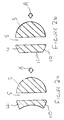
- slight variations can be made to the shape of the vortex generator 9, in particular to the downstream cylinder 4, as shown in Figure 2.
- the downstream cylinder 4 has flat sides 10 (instead of part-circular), typically inclined at 20° to the axis of the flow tube 1 while in Figure 2b, the downstream cylinder 4 has a flat rear face 11 (instead of concave), as well as the flat sides 10 of Figure 2a.
- the gap 5 can be increased in width to up to 50% of the diameter of the upstream cylinder, while the upstream cylinder 3 can be semi-ellipsoidal instead of semi-circular.
Landscapes
- Physics & Mathematics (AREA)
- Fluid Mechanics (AREA)
- General Physics & Mathematics (AREA)
- Measuring Volume Flow (AREA)
Applications Claiming Priority (2)
| Application Number | Priority Date | Filing Date | Title |
|---|---|---|---|
| GB8915994 | 1989-07-12 | ||
| GB898915994A GB8915994D0 (en) | 1989-07-12 | 1989-07-12 | Vortex flowmeters |
Publications (3)
| Publication Number | Publication Date |
|---|---|
| EP0408355A2 true EP0408355A2 (fr) | 1991-01-16 |
| EP0408355A3 EP0408355A3 (en) | 1991-04-10 |
| EP0408355B1 EP0408355B1 (fr) | 1994-04-20 |
Family
ID=10659947
Family Applications (1)
| Application Number | Title | Priority Date | Filing Date |
|---|---|---|---|
| EP90307615A Expired - Lifetime EP0408355B1 (fr) | 1989-07-12 | 1990-07-11 | Débimètres à tourbillons |
Country Status (5)
| Country | Link |
|---|---|
| US (1) | US5150619A (fr) |
| EP (1) | EP0408355B1 (fr) |
| CA (1) | CA2020530A1 (fr) |
| DE (1) | DE69008257T2 (fr) |
| GB (2) | GB8915994D0 (fr) |
Cited By (3)
| Publication number | Priority date | Publication date | Assignee | Title |
|---|---|---|---|---|
| WO1995025943A1 (fr) * | 1994-03-23 | 1995-09-28 | Schlumberger Industries S.A. | Compteur de fluide a tourbillons comportant un double obstacle |
| NL1009797C2 (nl) * | 1998-08-03 | 2000-02-04 | Tno | Inrichting voor het meten van de volumestroom van een fluïdum in een leiding. |
| WO2026049978A1 (fr) * | 2024-08-26 | 2026-03-05 | Mozarc Medical Us Llc | Détecteur d'écoulement |
Families Citing this family (21)
| Publication number | Priority date | Publication date | Assignee | Title |
|---|---|---|---|---|
| US6003383A (en) * | 1994-03-23 | 1999-12-21 | Schlumberger Industries, S.A. | Vortex fluid meter incorporating a double obstacle |
| US8291979B2 (en) * | 2007-03-27 | 2012-10-23 | Schlumberger Technology Corporation | Controlling flows in a well |
| US7814976B2 (en) * | 2007-08-30 | 2010-10-19 | Schlumberger Technology Corporation | Flow control device and method for a downhole oil-water separator |
| US8006757B2 (en) * | 2007-08-30 | 2011-08-30 | Schlumberger Technology Corporation | Flow control system and method for downhole oil-water processing |
| WO2011161298A1 (fr) * | 2010-06-21 | 2011-12-29 | Sami Lakka | Capteur d'écoulement |
| US9010197B1 (en) | 2010-09-21 | 2015-04-21 | The United States Of America As Represented By The Secretary Of The Navy | System for amplifying flow-induced vibration energy using boundary layer and wake flow control |
| US8925391B2 (en) * | 2011-11-04 | 2015-01-06 | Tao Of Systems Integration, Inc. | System and method for determining fluid speed |
| US9863974B2 (en) | 2014-12-02 | 2018-01-09 | Tao Of Systems Integration, Inc. | Method and system for determining aerodynamic loads from downstream flow properties |
| US10367434B2 (en) * | 2017-05-30 | 2019-07-30 | Saudi Arabian Oil Company | Harvesting energy from fluid flow |
| US11187044B2 (en) | 2019-12-10 | 2021-11-30 | Saudi Arabian Oil Company | Production cavern |
| US11339636B2 (en) | 2020-05-04 | 2022-05-24 | Saudi Arabian Oil Company | Determining the integrity of an isolated zone in a wellbore |
| US11460330B2 (en) | 2020-07-06 | 2022-10-04 | Saudi Arabian Oil Company | Reducing noise in a vortex flow meter |
| US11519767B2 (en) | 2020-09-08 | 2022-12-06 | Saudi Arabian Oil Company | Determining fluid parameters |
| US11920469B2 (en) | 2020-09-08 | 2024-03-05 | Saudi Arabian Oil Company | Determining fluid parameters |
| US11530597B2 (en) | 2021-02-18 | 2022-12-20 | Saudi Arabian Oil Company | Downhole wireless communication |
| US11603756B2 (en) | 2021-03-03 | 2023-03-14 | Saudi Arabian Oil Company | Downhole wireless communication |
| US11644351B2 (en) | 2021-03-19 | 2023-05-09 | Saudi Arabian Oil Company | Multiphase flow and salinity meter with dual opposite handed helical resonators |
| US11913464B2 (en) | 2021-04-15 | 2024-02-27 | Saudi Arabian Oil Company | Lubricating an electric submersible pump |
| US11619114B2 (en) | 2021-04-15 | 2023-04-04 | Saudi Arabian Oil Company | Entering a lateral branch of a wellbore with an assembly |
| US11994016B2 (en) | 2021-12-09 | 2024-05-28 | Saudi Arabian Oil Company | Downhole phase separation in deviated wells |
| US12085687B2 (en) | 2022-01-10 | 2024-09-10 | Saudi Arabian Oil Company | Model-constrained multi-phase virtual flow metering and forecasting with machine learning |
Family Cites Families (8)
| Publication number | Priority date | Publication date | Assignee | Title |
|---|---|---|---|---|
| US3650152A (en) * | 1968-02-13 | 1972-03-21 | American Standard Inc | Apparatus and method for measuring the velocity of a flowing fluid |
| US3589185A (en) * | 1969-09-04 | 1971-06-29 | Fischer & Porter Co | Vortex type flowmeter |
| JPS4978573A (fr) * | 1972-11-30 | 1974-07-29 | ||
| JPS50148722A (fr) * | 1974-05-22 | 1975-11-28 | ||
| US4030355A (en) * | 1976-06-18 | 1977-06-21 | Fischer & Porter Co. | Obstacle assembly for vortex type flowmeter |
| US4445388A (en) * | 1983-09-26 | 1984-05-01 | Fischer & Porter Company | Dual-body vortex-shedding flowmeter |
| US4838092A (en) * | 1986-03-15 | 1989-06-13 | Oval Engineering Co., Ltd. | Vortex flow meter |
| US4782710A (en) * | 1986-04-30 | 1988-11-08 | Fuji Electric Co., Ltd. | Karman vortex flow meter |
-
1989
- 1989-07-12 GB GB898915994A patent/GB8915994D0/en active Pending
-
1990
- 1990-07-05 US US07/548,396 patent/US5150619A/en not_active Expired - Fee Related
- 1990-07-05 CA CA002020530A patent/CA2020530A1/fr not_active Abandoned
- 1990-07-11 EP EP90307615A patent/EP0408355B1/fr not_active Expired - Lifetime
- 1990-07-11 DE DE69008257T patent/DE69008257T2/de not_active Expired - Fee Related
- 1990-07-11 GB GB9015221A patent/GB2234590B/en not_active Expired - Fee Related
Cited By (6)
| Publication number | Priority date | Publication date | Assignee | Title |
|---|---|---|---|---|
| WO1995025943A1 (fr) * | 1994-03-23 | 1995-09-28 | Schlumberger Industries S.A. | Compteur de fluide a tourbillons comportant un double obstacle |
| FR2717896A1 (fr) * | 1994-03-23 | 1995-09-29 | Schlumberger Ind Sa | Compteur de fluide à tourbillons comportant un double obstacle. |
| NL1009797C2 (nl) * | 1998-08-03 | 2000-02-04 | Tno | Inrichting voor het meten van de volumestroom van een fluïdum in een leiding. |
| WO2000008420A1 (fr) * | 1998-08-03 | 2000-02-17 | Nederlandse Organisatie Voor Toegepast- Natuurwetenschappijk Onderzoek Tno | Dispositif servant a mesurer le debit volumetrique d'un fluide dans un conduit |
| JP2002522756A (ja) * | 1998-08-03 | 2002-07-23 | ネーデルランセ オルハニサチエ フォール トゥーヘパスト−ナツールウェーテンシャッペルック オンデルズク テーエヌオー | パイプ内の液体の流量を測定するための装置 |
| WO2026049978A1 (fr) * | 2024-08-26 | 2026-03-05 | Mozarc Medical Us Llc | Détecteur d'écoulement |
Also Published As
| Publication number | Publication date |
|---|---|
| EP0408355A3 (en) | 1991-04-10 |
| GB8915994D0 (en) | 1989-08-31 |
| DE69008257T2 (de) | 1994-11-24 |
| CA2020530A1 (fr) | 1991-01-13 |
| US5150619A (en) | 1992-09-29 |
| GB2234590B (en) | 1993-07-21 |
| GB9015221D0 (en) | 1990-08-29 |
| EP0408355B1 (fr) | 1994-04-20 |
| DE69008257D1 (de) | 1994-05-26 |
| GB2234590A (en) | 1991-02-06 |
Similar Documents
| Publication | Publication Date | Title |
|---|---|---|
| US5150619A (en) | Vortex flowmeters | |
| US4448081A (en) | Method and device for the dynamic and density-independent determination of mass flow | |
| Sumner et al. | Flow-pattern identification for two staggered circular cylinders in cross-flow | |
| US3732731A (en) | Bluff body flowmeter with internal sensor | |
| EP0048588B1 (fr) | Débitmètre à induction de vortex et procédé de mesure de débit | |
| US4003253A (en) | Multi-range vortex-shedding flowmeter | |
| US4074571A (en) | Obstacle assembly for vortex type flowmeter | |
| US4297898A (en) | Stabilized vortex-shedding flowmeter | |
| US3948097A (en) | Flow velocity measuring device | |
| GB1566416A (en) | Flowmeter apparatus | |
| EP0337996B1 (fr) | Debimetres a tourbillons emportes par le courant | |
| GB2161941A (en) | Mass flow meter | |
| US4485679A (en) | Fluid flowmeter | |
| US3720104A (en) | Flowmeters | |
| US4030355A (en) | Obstacle assembly for vortex type flowmeter | |
| Shirakashi et al. | Characteristics of periodic vortex shedding from two cylinders in cruciform arrangement | |
| EP0106881B1 (fr) | Corps a profil etroit de formation de tourbillon | |
| US4003251A (en) | Acceleration-proof vortex-type flowmeter | |
| Yamasaki | Progress in hydrodynamic oscillator type flowmeters | |
| US4312237A (en) | Vortex generating device | |
| Vidyarthia et al. | Ultrasonic transit-time flowmeters for pipes: A short review | |
| EP0309607B1 (fr) | Capteur de débit avec déflecteur générant des oscillations fluidiques | |
| EP0032059B1 (fr) | Dispositif générateur de tourbillons | |
| JP3463241B2 (ja) | 渦流量計 | |
| US4441372A (en) | Vortex flowmeter |
Legal Events
| Date | Code | Title | Description |
|---|---|---|---|
| PUAI | Public reference made under article 153(3) epc to a published international application that has entered the european phase |
Free format text: ORIGINAL CODE: 0009012 |
|
| AK | Designated contracting states |
Kind code of ref document: A2 Designated state(s): DE ES FR IT NL |
|
| PUAL | Search report despatched |
Free format text: ORIGINAL CODE: 0009013 |
|
| AK | Designated contracting states |
Kind code of ref document: A3 Designated state(s): DE ES FR IT NL |
|
| 17P | Request for examination filed |
Effective date: 19910816 |
|
| 17Q | First examination report despatched |
Effective date: 19930205 |
|
| GRAA | (expected) grant |
Free format text: ORIGINAL CODE: 0009210 |
|
| AK | Designated contracting states |
Kind code of ref document: B1 Designated state(s): DE ES FR IT NL |
|
| PG25 | Lapsed in a contracting state [announced via postgrant information from national office to epo] |
Ref country code: IT Free format text: LAPSE BECAUSE OF FAILURE TO SUBMIT A TRANSLATION OF THE DESCRIPTION OR TO PAY THE FEE WITHIN THE PRE;WARNING: LAPSES OF ITALIAN PATENTS WITH EFFECTIVE DATE BEFORE 2007 MAY HAVE OCCURRED AT ANY TIME BEFORE 2007. THE CORRECT EFFECTIVE DATE MAY BE DIFFERENT FROM THE ONE RECORDED.SCRIBED TIME-LIMIT Effective date: 19940420 Ref country code: NL Effective date: 19940420 Ref country code: ES Free format text: THE PATENT HAS BEEN ANNULLED BY A DECISION OF A NATIONAL AUTHORITY Effective date: 19940420 |
|
| REF | Corresponds to: |
Ref document number: 69008257 Country of ref document: DE Date of ref document: 19940526 |
|
| PGFP | Annual fee paid to national office [announced via postgrant information from national office to epo] |
Ref country code: FR Payment date: 19940722 Year of fee payment: 5 |
|
| ET | Fr: translation filed | ||
| PGFP | Annual fee paid to national office [announced via postgrant information from national office to epo] |
Ref country code: DE Payment date: 19940901 Year of fee payment: 5 |
|
| NLV1 | Nl: lapsed or annulled due to failure to fulfill the requirements of art. 29p and 29m of the patents act | ||
| PLBE | No opposition filed within time limit |
Free format text: ORIGINAL CODE: 0009261 |
|
| STAA | Information on the status of an ep patent application or granted ep patent |
Free format text: STATUS: NO OPPOSITION FILED WITHIN TIME LIMIT |
|
| 26N | No opposition filed | ||
| PG25 | Lapsed in a contracting state [announced via postgrant information from national office to epo] |
Ref country code: DE Effective date: 19960402 |
|
| PG25 | Lapsed in a contracting state [announced via postgrant information from national office to epo] |
Ref country code: FR Effective date: 19960430 |
|
| REG | Reference to a national code |
Ref country code: FR Ref legal event code: ST |
|
| REG | Reference to a national code |
Ref country code: FR Ref legal event code: ST |
|
| REG | Reference to a national code |
Ref country code: FR Ref legal event code: ST |
|
| REG | Reference to a national code |
Ref country code: FR Ref legal event code: GC |
|
| REG | Reference to a national code |
Ref country code: FR Ref legal event code: DG |