EP0408532B1 - Tandem-montierte, stirnseitige Dichtungen - Google Patents
Tandem-montierte, stirnseitige Dichtungen Download PDFInfo
- Publication number
- EP0408532B1 EP0408532B1 EP90850235A EP90850235A EP0408532B1 EP 0408532 B1 EP0408532 B1 EP 0408532B1 EP 90850235 A EP90850235 A EP 90850235A EP 90850235 A EP90850235 A EP 90850235A EP 0408532 B1 EP0408532 B1 EP 0408532B1
- Authority
- EP
- European Patent Office
- Prior art keywords
- seal member
- seal
- sealing apparatus
- chamber
- flexible
- Prior art date
- Legal status (The legal status is an assumption and is not a legal conclusion. Google has not performed a legal analysis and makes no representation as to the accuracy of the status listed.)
- Expired - Lifetime
Links
- 210000004907 gland Anatomy 0.000 claims description 12
- 238000007789 sealing Methods 0.000 claims description 11
- 230000003068 static effect Effects 0.000 claims description 10
- 239000000463 material Substances 0.000 claims description 6
- 239000000356 contaminant Substances 0.000 claims description 5
- 229920000642 polymer Polymers 0.000 claims 1
- 150000002825 nitriles Chemical class 0.000 description 2
- 229910001369 Brass Inorganic materials 0.000 description 1
- 229910000906 Bronze Inorganic materials 0.000 description 1
- 229910000831 Steel Inorganic materials 0.000 description 1
- 239000010951 brass Substances 0.000 description 1
- 239000010974 bronze Substances 0.000 description 1
- 238000011109 contamination Methods 0.000 description 1
- KUNSUQLRTQLHQQ-UHFFFAOYSA-N copper tin Chemical compound [Cu].[Sn] KUNSUQLRTQLHQQ-UHFFFAOYSA-N 0.000 description 1
- -1 dirt Substances 0.000 description 1
- 239000000428 dust Substances 0.000 description 1
- HQQADJVZYDDRJT-UHFFFAOYSA-N ethene;prop-1-ene Chemical group C=C.CC=C HQQADJVZYDDRJT-UHFFFAOYSA-N 0.000 description 1
- 238000005461 lubrication Methods 0.000 description 1
- 239000002861 polymer material Substances 0.000 description 1
- 238000005086 pumping Methods 0.000 description 1
- 239000010959 steel Substances 0.000 description 1
- XLYOFNOQVPJJNP-UHFFFAOYSA-N water Substances O XLYOFNOQVPJJNP-UHFFFAOYSA-N 0.000 description 1
Images
Classifications
-
- F—MECHANICAL ENGINEERING; LIGHTING; HEATING; WEAPONS; BLASTING
- F16—ENGINEERING ELEMENTS AND UNITS; GENERAL MEASURES FOR PRODUCING AND MAINTAINING EFFECTIVE FUNCTIONING OF MACHINES OR INSTALLATIONS; THERMAL INSULATION IN GENERAL
- F16J—PISTONS; CYLINDERS; SEALINGS
- F16J15/00—Sealings
- F16J15/16—Sealings between relatively-moving surfaces
- F16J15/34—Sealings between relatively-moving surfaces with slip-ring pressed against a more or less radial face on one member
- F16J15/3436—Pressing means
- F16J15/3456—Pressing means without external means for pressing the ring against the face, e.g. slip-ring with a resilient lip
-
- F—MECHANICAL ENGINEERING; LIGHTING; HEATING; WEAPONS; BLASTING
- F04—POSITIVE - DISPLACEMENT MACHINES FOR LIQUIDS; PUMPS FOR LIQUIDS OR ELASTIC FLUIDS
- F04D—NON-POSITIVE-DISPLACEMENT PUMPS
- F04D29/00—Details, component parts, or accessories
- F04D29/08—Sealings
- F04D29/10—Shaft sealings
- F04D29/106—Shaft sealings especially adapted for liquid pumps
-
- F—MECHANICAL ENGINEERING; LIGHTING; HEATING; WEAPONS; BLASTING
- F16—ENGINEERING ELEMENTS AND UNITS; GENERAL MEASURES FOR PRODUCING AND MAINTAINING EFFECTIVE FUNCTIONING OF MACHINES OR INSTALLATIONS; THERMAL INSULATION IN GENERAL
- F16J—PISTONS; CYLINDERS; SEALINGS
- F16J15/00—Sealings
- F16J15/002—Sealings comprising at least two sealings in succession
Definitions
- the invention relates to pump seals, and more particularly to a static seal arrangement for centrifugal pumps with dynamic seal arrangements.
- US Patent No. 4,186,929 shows another type arrangement with a conventional lip seal, a non-flexible washer, and a flexible member.
- the conventional lip seal requires lubrication, and the flexible members run with a relatively big axial gap. At static conditions, the axial gap will get packed with contaminants. When pressure occurs, it forces contaminants into the lip seal area. In addition, the flexible member does not perform effectively because of the axial gap.
- French Patent 2 381 952 shows another solution with a tandem lip seal arrangement in a gland chamber, both seals being provided with flexible lips, which are sensitive to contaminants.
- tandem mounted face seals are an advance over the prior art arrangements represented above, and provide a novel solution to overcome severe application problems where high static or dynamic pressure occurs.
- Another object of the invention is to provide tandem mounted pump face seals, with one seal flexible and another seal less or non-flexible.
- the face seal with the flexible lip performs the primary sealing function and the face seal with the non-flexible lip functions as a deflector during rotation of the pump impeller to prevent leakage at the flexible lip when high static or dynamic pressures occur.
- tandem mounted face seals are mounted between the dynamic seal arrangement and the frame of a centrifugal pump.
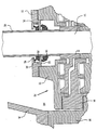
- an impeller shaft 10 has mounted thereon a first stage expeller and a second stage expeller 14 which coact with end plate 16 and inner plate 18 to form in a known manner a two stage dynamic seal 20.
- Gland 22 is fastened to end plate 16 and may be fabricated from steel, bronze, or brass material.
- Gland 22 includes a gland insert 24 which may be of similar material. Gland 22 and gland insert 24 are spaced from shaft sleeve 26 to permit passage of the shaft through the central opening.
- a flexible lip face seal 28 is press mounted on shaft sleeve 26 within gland chamber 30 formed by the gland 22 and insert 24.
- a non-flexible lip face seal 32 is also press mounted on shaft sleeve 26. The lip of seal 28 is positioned to press firmly against counter face 29, and the lip of seal 32 is positioned to press firmly against counter face 33.
- seal suitable to perform the function of the flexible lip face seal is a Forsheda V-ring seal (Forsheda Shaft Seal Corporation, Cleveland, Ohio) made from a rubber grade material, for example, Nitrile, Neopren, Vitron.
- seal suitable to perform the function of the non-flexible lip face seal is a Checkseal (Greene, Tweed & Co., Northwales, Pa.), made from, for example, a polymer material such as a carboxylated nitrile, fluroelastomer, or ethylene propylene depending on the service conditions.
- Pump frame portion 34 forms part of the dynamic seal cavity 35, and dynamic seal stuffing box portion 36 is positioned between the impeller housing (not shown) and the frame 34.
- Dynamic seal stuffing box portion 36 is connected to the pump housing as are plates 16, 18.
- the face seal 28 with the flexible lip performs the primary sealing function.
- the flexible lip face seal seals at low static pressures from 0 to 35 kPa (0 to 5 psi).
- the non-flexible lip face seal functions as a flinger-deflector during rotation of the impeller to propel contamination away from seal 28 to protect seal 28 from high pressures at least up to 210 kPa (30 psi). If high pressure occurs and seal 28 starts to leak, the differential pressure created between the two seals 28, 32 will force seal 32 against the counter face 33 to prevent leakage.
- Material of the non-flexible seal is selected depending on the maximum static pressure which can occur during the pumping operation.
- the flexible seal is installed in the box like enclosure of the gland, and the non-flexible is run against the outside surface of the box like enclosure.
- Both of the face seals are self-adjusting, shaft mounted and used to deflect and exclude contaminants such as dust, dirt, mud and water migrating from the impeller housing to the stuffing box. Both seals are easily mounted on and rotate with the impeller shaft. The seals self-adjust after several rotations of the impeller shaft. It will be readily understood by those skilled in the art that the tandem seal arrangement of the invention is most suitable for severe applications where high static or dynamic pressure occurs.
Landscapes
- Engineering & Computer Science (AREA)
- General Engineering & Computer Science (AREA)
- Mechanical Engineering (AREA)
- Sealing Devices (AREA)
- Structures Of Non-Positive Displacement Pumps (AREA)
- Sealing With Elastic Sealing Lips (AREA)
Claims (8)
- Dichtungsvorrichtung für eine drehbare Welle, mit einer statischen Tandem-Dichtungsanordnung, wobei letztere ein erstes Dichtungselement (28) mit einer auf der Welle (10) angebrachten flexiblen Lippe aufweist und eine feststehende Stopfbüchseneinrichtung (22) mit einer zentralen Öffnung und einer Stopfbüchseneinrichtungs-Kammer (30) versehen ist, durch die sich die Welle (10) mit Spiel hindurcherstreckt und die das Dichtungselement (28) enthält, dessen flexible Lippe gegen eine Innenwandung (29) der Kammer (30) gedrückt wird, und wobei das andere Dichtungselement (32) der statischen Tandem-Dichtung in axialer Beabstandung von dem ersten Dichtungselement (28) auf der Welle (10) angebracht ist,
dadurch gekennzeichnet, daß das andere Dichtungselement (32) mit einer nicht-flexiblen Lippe versehen ist, die gegen eine Außenwandung (33) der Kammer (30) gedrückt ist, wobei das andere Dichtungselement (32) als Ablenkeinrichtung zum Wegtreiben von Verunreinigungen von dem Dichtungselement (28) weg sowie zum Verhindern eines Leckens bei hohen Drücken wirkt, wobei die Dichtungsvorrichtung weiterhin eine dynamische Dichtungsanordnung (20) aufweist, die angrenzend an das zweite Dichtungselement (32) sowie entfernt von dem ersten Dichtungselement (28) positioniert ist, und daß die flexible sowie die nicht-flexible Lippe in derselben Richtung von der dynamischen Dichtungsanordnung (20) wegragen. - Dichtungsvorrichtung nach Anspruch 1,
dadurch gekennzeichnet, daß die Stopfbüchseneinrichtung (22) einen L-förmigen Ringelementeinsatz (24) beinhaltet, der einen Teil der Kammer (30) bildet. - Dichtungsvorrichtung nach Anspruch 1,
dadurch gekennzeichnet, daß das Dichtungselement (28) eine wirksame Dichtung bei statischen Drücken von 0 bis 35 kPa (5 psi) schafft. - Dichtungsanordnung nach Anspruch 3,
dadurch gekennzeichnet, daß das Dichtungselement (28) aus einem gummiartigen Material hergestellt ist. - Dichtungsvorrichtung nach Anspruch 1,
dadurch gekennzeichnet, daß das andere Dichtungselement (32) aus einem polymerartigen Material hergestellt ist. - Dichtungsvorrichtung nach Anspruch 5,
dadurch gekennzeichnet, daß das andere Dichtungselement (32) gegen die Außenwandungs-Stirnseite (33) der Kammer (30) gedrückt wird und ein Lecken in Richtung von der dynamischen Dichtung (20) weg verhindert, wenn ein Lecken bei letzterer zu einer Druckerhöhung in diesem Bereich gegenüber dem Druck in der Kammer (30) führen würde. - Dichtungsvorrichtung nach Anspruch 1,
dadurch gekennzeichnet, daß ein Hülsenelement (26) zur Anbringung des Dichtungselements (28) sowie des anderen Dichtungselements (32) auf der Welle (10) angeordnet ist, wobei das Hülsenelement an einem Rotationselement (14) der dynamischen Dichtung (20) anliegt. - Dichtungsvorrichtung nach Anspruch 1,
dadurch gekennzeichnet, daß das andere Dichtungselement (32) in wirksamer Weise ein Lecken bei Drücken von mehr als 140 kPa (20 psi) verhindert.
Applications Claiming Priority (2)
| Application Number | Priority Date | Filing Date | Title |
|---|---|---|---|
| US380164 | 1989-07-14 | ||
| US07/380,164 US4973063A (en) | 1989-07-14 | 1989-07-14 | Tandem mounted face seals |
Publications (2)
| Publication Number | Publication Date |
|---|---|
| EP0408532A1 EP0408532A1 (de) | 1991-01-16 |
| EP0408532B1 true EP0408532B1 (de) | 1995-12-06 |
Family
ID=23500136
Family Applications (1)
| Application Number | Title | Priority Date | Filing Date |
|---|---|---|---|
| EP90850235A Expired - Lifetime EP0408532B1 (de) | 1989-07-14 | 1990-06-13 | Tandem-montierte, stirnseitige Dichtungen |
Country Status (4)
| Country | Link |
|---|---|
| US (1) | US4973063A (de) |
| EP (1) | EP0408532B1 (de) |
| CA (1) | CA2021157C (de) |
| DE (1) | DE69023975T2 (de) |
Families Citing this family (9)
| Publication number | Priority date | Publication date | Assignee | Title |
|---|---|---|---|---|
| US5058487A (en) * | 1990-05-01 | 1991-10-22 | Litton Industrial Automation Systems, Inc. | Cylinder with radially movable rod |
| BR9106184A (pt) * | 1990-10-11 | 1993-03-16 | Rotoflex Inc | Dispositivo de vedacao de arvore rotativa |
| US5356158A (en) * | 1990-10-11 | 1994-10-18 | Rotoflex, Inc. | Resilient rotary seal with projecting edge |
| SE507745C2 (sv) * | 1996-11-05 | 1998-07-06 | Alfa Laval Ab | Tätningsanordning |
| CA2309238C (en) | 2000-05-24 | 2002-07-30 | T & E Oils Ltd. | Assemblies for modular fluid pump |
| NL1026756C2 (nl) * | 2004-07-30 | 2006-01-31 | Tetra Laval Holdings & Finance | Afdichtconstructie. |
| US9739379B2 (en) * | 2011-04-20 | 2017-08-22 | Dresser-Rand Company | High moisture environment seal assembly |
| US9989095B2 (en) * | 2013-11-14 | 2018-06-05 | Schaeffler Technologies AG & Co. KG | Water pump bearing with integrated mechanical seal |
| CO2021005972U1 (es) * | 2020-06-15 | 2021-05-20 | Ramirez Nunez Gabriel | Sistema de sellado para rodillos a prueba de intrusión de materiales externos, empleados en bandas de transportación de materiales a granel |
Family Cites Families (12)
| Publication number | Priority date | Publication date | Assignee | Title |
|---|---|---|---|---|
| US3015505A (en) * | 1959-01-12 | 1962-01-02 | Southwestern Cotton Oil Compan | Packing gland for vertical screw conveyor |
| FR1459069A (fr) * | 1964-09-11 | 1966-04-29 | Forsheda Gummifabrik Ab | Bagues d'étanchéité perfectionnées |
| US3703296A (en) * | 1970-05-20 | 1972-11-21 | Forsheda Gummifabrik Ab | Sealing between a rotary and a stationary member |
| US3693985A (en) * | 1971-05-12 | 1972-09-26 | Arthur M Dillner | End face fluid seal unit |
| US4094512A (en) * | 1976-07-14 | 1978-06-13 | Crane Packing Limited | Shaft seals |
| SE404414B (sv) * | 1977-02-25 | 1978-10-02 | Alfa Laval Ab | Anordning for att diska en forsta tetningsring och ett utrymme nermast intill tetningsringen |
| GB1547733A (en) * | 1977-11-24 | 1979-06-27 | Plessey Co Ltd | Hydraulic pump with a sealing arrangement |
| US4194745A (en) * | 1979-05-02 | 1980-03-25 | Mcdougal Thomas L | Controlled clearance seal |
| CA1136665A (en) * | 1979-11-27 | 1982-11-30 | Ernst A. Kronenberg | Shaft seal of the type incorporating a sealing flange |
| JPS6015975Y2 (ja) * | 1980-10-21 | 1985-05-18 | エヌオーケー株式会社 | 密封装置 |
| US4580789A (en) * | 1984-10-23 | 1986-04-08 | Ludlow Industries, Inc. | Shaft seal construction for bin level indicators |
| US4832511A (en) * | 1988-08-16 | 1989-05-23 | Reliance Electric Company | High efficiency seal devices for shaft bearings |
-
1989
- 1989-07-14 US US07/380,164 patent/US4973063A/en not_active Expired - Lifetime
-
1990
- 1990-06-13 EP EP90850235A patent/EP0408532B1/de not_active Expired - Lifetime
- 1990-06-13 DE DE69023975T patent/DE69023975T2/de not_active Expired - Fee Related
- 1990-07-13 CA CA002021157A patent/CA2021157C/en not_active Expired - Fee Related
Also Published As
| Publication number | Publication date |
|---|---|
| CA2021157C (en) | 1997-10-21 |
| EP0408532A1 (de) | 1991-01-16 |
| US4973063A (en) | 1990-11-27 |
| DE69023975T2 (de) | 1996-05-15 |
| CA2021157A1 (en) | 1991-01-15 |
| DE69023975D1 (de) | 1996-01-18 |
Similar Documents
| Publication | Publication Date | Title |
|---|---|---|
| EP0470409B1 (de) | Berührungsfreie Gleitringdichtung | |
| US4884945A (en) | Dynamic seal arrangement for impeller pump | |
| US6210107B1 (en) | Barrier seal systems | |
| US4890941A (en) | Bearing protector with slinger ring | |
| US6520506B2 (en) | Radial shaft seal | |
| EP0408532B1 (de) | Tandem-montierte, stirnseitige Dichtungen | |
| JPS6229662B2 (de) | ||
| US6056293A (en) | Sealing assembly for a rotary shaft, in particular of an automotive engine water pump | |
| EP0427553B2 (de) | Wellendichtungsanordnung | |
| US3377073A (en) | Shaft seal | |
| EP0410948B1 (de) | Dynamische Abdichtung mit Spülflüssigkeit zum Schutz der statischen Dichtung | |
| MX2008008722A (es) | Arreglo de sello de anillo flotante flexible para bombas rotodinamicas. | |
| US5823539A (en) | Environmentally safe pump having a bellows seal and a split ring shaft seal | |
| US3887200A (en) | Rotary seal assembly | |
| EP0260441B1 (de) | Dichtung | |
| US6073934A (en) | Mechanical seal | |
| US5678828A (en) | Sealing device | |
| US2583777A (en) | Shaft seal | |
| USRE34319E (en) | Dynamic seal arrangement for impeller pump | |
| RU2031288C1 (ru) | Торцевое контактное уплотнение вращающегося вала | |
| JP3940869B2 (ja) | オイルシール | |
| US20030015843A1 (en) | High speed high pressure rotary | |
| AU2004248094B2 (en) | Pressure resistant static and dynamic expeller shaft sealing | |
| KR0181398B1 (ko) | 펌프의 씰링장치 | |
| KR200262385Y1 (ko) | 원심펌프의 임펠러축 펌프실 실링구조 |
Legal Events
| Date | Code | Title | Description |
|---|---|---|---|
| PUAI | Public reference made under article 153(3) epc to a published international application that has entered the european phase |
Free format text: ORIGINAL CODE: 0009012 |
|
| AK | Designated contracting states |
Kind code of ref document: A1 Designated state(s): DE FR GB IT SE |
|
| 17P | Request for examination filed |
Effective date: 19910201 |
|
| 17Q | First examination report despatched |
Effective date: 19921026 |
|
| GRAA | (expected) grant |
Free format text: ORIGINAL CODE: 0009210 |
|
| AK | Designated contracting states |
Kind code of ref document: B1 Designated state(s): DE FR GB IT SE |
|
| REF | Corresponds to: |
Ref document number: 69023975 Country of ref document: DE Date of ref document: 19960118 |
|
| ITF | It: translation for a ep patent filed | ||
| ET | Fr: translation filed | ||
| PGFP | Annual fee paid to national office [announced via postgrant information from national office to epo] |
Ref country code: GB Payment date: 19960604 Year of fee payment: 7 |
|
| PGFP | Annual fee paid to national office [announced via postgrant information from national office to epo] |
Ref country code: FR Payment date: 19960627 Year of fee payment: 7 |
|
| PGFP | Annual fee paid to national office [announced via postgrant information from national office to epo] |
Ref country code: SE Payment date: 19960701 Year of fee payment: 7 |
|
| PGFP | Annual fee paid to national office [announced via postgrant information from national office to epo] |
Ref country code: DE Payment date: 19960826 Year of fee payment: 7 |
|
| PLBE | No opposition filed within time limit |
Free format text: ORIGINAL CODE: 0009261 |
|
| STAA | Information on the status of an ep patent application or granted ep patent |
Free format text: STATUS: NO OPPOSITION FILED WITHIN TIME LIMIT |
|
| 26N | No opposition filed | ||
| PG25 | Lapsed in a contracting state [announced via postgrant information from national office to epo] |
Ref country code: GB Free format text: LAPSE BECAUSE OF NON-PAYMENT OF DUE FEES Effective date: 19970613 |
|
| PG25 | Lapsed in a contracting state [announced via postgrant information from national office to epo] |
Ref country code: SE Effective date: 19970614 |
|
| GBPC | Gb: european patent ceased through non-payment of renewal fee |
Effective date: 19970613 |
|
| PG25 | Lapsed in a contracting state [announced via postgrant information from national office to epo] |
Ref country code: FR Free format text: LAPSE BECAUSE OF NON-PAYMENT OF DUE FEES Effective date: 19980227 |
|
| EUG | Se: european patent has lapsed |
Ref document number: 90850235.4 |
|
| PG25 | Lapsed in a contracting state [announced via postgrant information from national office to epo] |
Ref country code: DE Free format text: LAPSE BECAUSE OF NON-PAYMENT OF DUE FEES Effective date: 19980303 |
|
| REG | Reference to a national code |
Ref country code: FR Ref legal event code: ST |
|
| REG | Reference to a national code |
Ref country code: FR Ref legal event code: ST |
|
| PG25 | Lapsed in a contracting state [announced via postgrant information from national office to epo] |
Ref country code: IT Free format text: LAPSE BECAUSE OF NON-PAYMENT OF DUE FEES Effective date: 20050613 |