EP0408560B1 - Verfahren und Vorrichtung zum automatischen Übereinstimmen von mindestens zwei kongruenten zylindrischen Flächen, insbesondere zum mechanischen Eingravieren - Google Patents
Verfahren und Vorrichtung zum automatischen Übereinstimmen von mindestens zwei kongruenten zylindrischen Flächen, insbesondere zum mechanischen Eingravieren Download PDFInfo
- Publication number
- EP0408560B1 EP0408560B1 EP89900814A EP89900814A EP0408560B1 EP 0408560 B1 EP0408560 B1 EP 0408560B1 EP 89900814 A EP89900814 A EP 89900814A EP 89900814 A EP89900814 A EP 89900814A EP 0408560 B1 EP0408560 B1 EP 0408560B1
- Authority
- EP
- European Patent Office
- Prior art keywords
- roll
- knurling tool
- freedom
- controlling
- range
- Prior art date
- Legal status (The legal status is an assumption and is not a legal conclusion. Google has not performed a legal analysis and makes no representation as to the accuracy of the status listed.)
- Expired - Lifetime
Links
- 238000000034 method Methods 0.000 title claims abstract description 27
- 230000003252 repetitive effect Effects 0.000 claims abstract description 5
- 230000005540 biological transmission Effects 0.000 claims description 7
- 238000005096 rolling process Methods 0.000 claims description 7
- 230000000295 complement effect Effects 0.000 claims description 6
- 238000006073 displacement reaction Methods 0.000 claims description 4
- 238000006243 chemical reaction Methods 0.000 claims description 3
- 239000000725 suspension Substances 0.000 claims description 3
- 230000003213 activating effect Effects 0.000 claims 2
- 230000001939 inductive effect Effects 0.000 claims 1
- 230000007797 corrosion Effects 0.000 abstract description 5
- 238000005260 corrosion Methods 0.000 abstract description 5
- 238000013461 design Methods 0.000 description 11
- 239000011295 pitch Substances 0.000 description 11
- 230000006870 function Effects 0.000 description 9
- 238000004049 embossing Methods 0.000 description 7
- 230000015654 memory Effects 0.000 description 7
- 230000001050 lubricating effect Effects 0.000 description 6
- 230000008878 coupling Effects 0.000 description 2
- 238000010168 coupling process Methods 0.000 description 2
- 238000005859 coupling reaction Methods 0.000 description 2
- 238000002347 injection Methods 0.000 description 2
- 239000007924 injection Substances 0.000 description 2
- 238000005461 lubrication Methods 0.000 description 2
- 238000002791 soaking Methods 0.000 description 2
- 230000002269 spontaneous effect Effects 0.000 description 2
- 238000011144 upstream manufacturing Methods 0.000 description 2
- 230000001133 acceleration Effects 0.000 description 1
- 238000012937 correction Methods 0.000 description 1
- 230000007547 defect Effects 0.000 description 1
- 230000000694 effects Effects 0.000 description 1
- 239000004744 fabric Substances 0.000 description 1
- 239000000314 lubricant Substances 0.000 description 1
- 239000000463 material Substances 0.000 description 1
- 238000012544 monitoring process Methods 0.000 description 1
- 238000002360 preparation method Methods 0.000 description 1
- 125000006850 spacer group Chemical group 0.000 description 1
- 230000003068 static effect Effects 0.000 description 1
- 239000000126 substance Substances 0.000 description 1
- 238000006467 substitution reaction Methods 0.000 description 1
- 238000012360 testing method Methods 0.000 description 1
- 238000013519 translation Methods 0.000 description 1
Images


Classifications
-
- B—PERFORMING OPERATIONS; TRANSPORTING
- B21—MECHANICAL METAL-WORKING WITHOUT ESSENTIALLY REMOVING MATERIAL; PUNCHING METAL
- B21H—MAKING PARTICULAR METAL OBJECTS BY ROLLING, e.g. SCREWS, WHEELS, RINGS, BARRELS, BALLS
- B21H8/00—Rolling metal of indefinite length in repetitive shapes specially designed for the manufacture of particular objects, e.g. checkered sheets
- B21H8/005—Embossing sheets or rolls
-
- B—PERFORMING OPERATIONS; TRANSPORTING
- B21—MECHANICAL METAL-WORKING WITHOUT ESSENTIALLY REMOVING MATERIAL; PUNCHING METAL
- B21H—MAKING PARTICULAR METAL OBJECTS BY ROLLING, e.g. SCREWS, WHEELS, RINGS, BARRELS, BALLS
- B21H7/00—Making articles not provided for in the preceding groups, e.g. agricultural tools, dinner forks, knives, spoons
- B21H7/14—Making articles not provided for in the preceding groups, e.g. agricultural tools, dinner forks, knives, spoons knurled articles
-
- B—PERFORMING OPERATIONS; TRANSPORTING
- B23—MACHINE TOOLS; METAL-WORKING NOT OTHERWISE PROVIDED FOR
- B23P—METAL-WORKING NOT OTHERWISE PROVIDED FOR; COMBINED OPERATIONS; UNIVERSAL MACHINE TOOLS
- B23P9/00—Treating or finishing surfaces mechanically, with or without calibrating, primarily to resist wear or impact, e.g. smoothing or roughening turbine blades or bearings; Features of such surfaces not otherwise provided for, their treatment being unspecified
- B23P9/02—Treating or finishing by applying pressure, e.g. knurling
-
- B—PERFORMING OPERATIONS; TRANSPORTING
- B23—MACHINE TOOLS; METAL-WORKING NOT OTHERWISE PROVIDED FOR
- B23Q—DETAILS, COMPONENTS, OR ACCESSORIES FOR MACHINE TOOLS, e.g. ARRANGEMENTS FOR COPYING OR CONTROLLING; MACHINE TOOLS IN GENERAL CHARACTERISED BY THE CONSTRUCTION OF PARTICULAR DETAILS OR COMPONENTS; COMBINATIONS OR ASSOCIATIONS OF METAL-WORKING MACHINES, NOT DIRECTED TO A PARTICULAR RESULT
- B23Q27/00—Geometrical mechanisms for the production of work of particular shapes, not fully provided for in another subclass
- B23Q27/006—Geometrical mechanisms for the production of work of particular shapes, not fully provided for in another subclass by rolling without slippage two bodies of particular shape relative to each other
-
- B—PERFORMING OPERATIONS; TRANSPORTING
- B44—DECORATIVE ARTS
- B44B—MACHINES, APPARATUS OR TOOLS FOR ARTISTIC WORK, e.g. FOR SCULPTURING, GUILLOCHING, CARVING, BRANDING, INLAYING
- B44B5/00—Machines or apparatus for embossing decorations or marks, e.g. embossing coins
- B44B5/0004—Machines or apparatus for embossing decorations or marks, e.g. embossing coins characterised by the movement of the embossing tool(s), or the movement of the work, during the embossing operation
- B44B5/0009—Rotating embossing tools
- B44B5/0014—Rotating embossing tools and rotating workpieces
-
- B—PERFORMING OPERATIONS; TRANSPORTING
- B44—DECORATIVE ARTS
- B44B—MACHINES, APPARATUS OR TOOLS FOR ARTISTIC WORK, e.g. FOR SCULPTURING, GUILLOCHING, CARVING, BRANDING, INLAYING
- B44B5/00—Machines or apparatus for embossing decorations or marks, e.g. embossing coins
- B44B5/0095—Machines or apparatus for embossing decorations or marks, e.g. embossing coins using computer control means
-
- B—PERFORMING OPERATIONS; TRANSPORTING
- B44—DECORATIVE ARTS
- B44B—MACHINES, APPARATUS OR TOOLS FOR ARTISTIC WORK, e.g. FOR SCULPTURING, GUILLOCHING, CARVING, BRANDING, INLAYING
- B44B5/00—Machines or apparatus for embossing decorations or marks, e.g. embossing coins
- B44B5/02—Dies; Accessories
- B44B5/026—Dies
-
- Y—GENERAL TAGGING OF NEW TECHNOLOGICAL DEVELOPMENTS; GENERAL TAGGING OF CROSS-SECTIONAL TECHNOLOGIES SPANNING OVER SEVERAL SECTIONS OF THE IPC; TECHNICAL SUBJECTS COVERED BY FORMER USPC CROSS-REFERENCE ART COLLECTIONS [XRACs] AND DIGESTS
- Y10—TECHNICAL SUBJECTS COVERED BY FORMER USPC
- Y10S—TECHNICAL SUBJECTS COVERED BY FORMER USPC CROSS-REFERENCE ART COLLECTIONS [XRACs] AND DIGESTS
- Y10S72/00—Metal deforming
- Y10S72/703—Knurling
Definitions
- the present invention relates to a process and apparatus for automatically matching and engaging two rolling and/or rocking substantially cylindrical surfaces. At least one of the substantially cylindrical surfaces is a knurling tool for mechanical emboss engraving particularly of rolls. The embossed rolls are used for embossing sheet materials and the like. Furthermore the present invention relates also to the mechanical engraved plates obtained with such process and means. Chemical corrosion can be used to complete the engraving process.
- an operator has the task to move the active surface of a knurling embossing tool, under pressure to mate with a generally cylindrical surface to be mechanically engraved or embossed.
- the size ratio, between one or more tools and the roll to be engraved is from 2 to 10 with reference to diameter and from 10 to 1000 referring to the whole roll length.
- the knurling tool must be displaced, at least longitudinally, a corresponding number of times. Each time the knurling tool is moved it must be checked against the correct matching reference to suitable markers.
- the longitudinal repetition pitch of the design exceeds 4-5 cm, a substantially double knurling tool length is needed.
- the invention as claimed, is intended to remedy these drawbacks.
- the inventor has conceived a process and means for automatically matching at least two engagement surfaces, that of knurling tool and that of roll to be engraved.
- This invention is particularly useful for mechanical emboss engraving, whereby the ranges of freedom (named as X, W, Y, Z) of the manually operable tool machine are mechanized and subjected to electronic control.
- a hardware structure is provided to be automatically driven by the software.
- the software can read the design to be engraved, and control the starting, repetitive and final steps, complying with locations and times. The operator's action is needed only for loading both the roll to be worked and the knurling tool for setting the position and starting the cycle and then for removal of the unfinished roll for the corrosion steps and for the final unloading.
- the machine substantially has a conventional structure, such as of a lathe-like machine, wherein the tool comprises a knurling tool.
- the machine has four ranges of freedom (named as X, W, Y, Z) including that (W) of substantially radial, which, is subjected to a press for radial approaching.
- the roll to be worked is moved (y1) by the action (y0) of a D.C. motor.
- the motor is controlled by a first encoder.
- the signals of the first encoder may be referred to as correct present settings of roll to be worked, even relatively to position, at least longitudinal (X) , of the knurling tool.
- the four ranges of freedom (X, W, Y, Z) , as well as the fastening condition (Y') , which occurs without turning of the knurling tool, are characterized as follow.
- Longitudinal movement (X) of the carriage, whereon the knurling tool carrier device is installed, is achieved by a conventional screw and/or bar of the machine tool.
- the conventional screw and/or bar are rotated by a separate second D.C. motor and the position of the carriage with respect to the roll is controlled by a second encoder.
- Limit switches may be installed at the ends of the roll to be worked.
- the second range of freedom (W) comprises a substantially radial, and substantially vertical, movement of approaching and removal of the knurling tool to and from the roll to be worked.
- Such range of freedom (W) includes a base place to be determined once manually.
- the base place is set by adjusting a screw, to determine the position chiefly centripetal to the angular excursion which is provided by a first class lever suspension.
- the power is provided by a pneumatic or hydraulic cylinder-piston unit, subjected to a hydraulic station, and is adapted to be driven by an electrovalve, and controlled by signals coming from a computerized electronic system.
- This second range of freedom (W) is limited by a limit switch.
- the third range of freedom (named as Y ) comprises rotation of the knurling tool around its axis.
- the rotation of knurling tool (which is substantially idle), is induced (y') by the roll to be worked, when the knurling tool engages it.
- the knurling tool although rotated on its Y axes when encountering the roll to be worked can be braked (y'') as needed by a brake device or a fastening device in the time period between detaching and re-approaching.
- the fourth range of freedom (named as Z) is comprised by angular movement of the knurling tool about a fixed fulcrum. Rolling of generatrixs of tangency may take place by a driver including a second class lever. The driver is powered by a screw loading a spring and has as resistance a substantially bridge-like support, carrying knurling tool. Vertical positioning of the knurling tool is provided by extending a piston within a fluidynamic cylinder, thereby providing operating pressure.
- This range of freedom (Z) is used only when the pitch or ratio, of the design to be engraved, is greater then 4-5 cm, and the corresponding length of the knurling tool is greater then 8 cm, with a barrel-like shape. Possible use of this fourth range of freedom (Z) is needed during movements regarding the third range of freedom (Y) .
- Control of these four ranges of freedom (X, W, Y, Z) conventionally was made manually, at least on driving and/or starting and/or adjusting and/or stopping.
- the present invention solves these specific problems.
- the lead screw is driven by a permanent magnet motor which is powered by a D.C. cable.
- a tele-reverser acts on the magnet and is placed within the electric panel.
- the lead screw is coupled in axial relationship with a second encoder whose input and output terminals are connected to an electric and electronic panel, to be described.
- the range of movement (X) of the carriage is limited by two limit switches. The limit switches are electrically connected, by wires, to the electric panel.
- the fluidynamic motor is fed by a hydraulic station.
- the electrovalve system and circuit associated thereto and controlling such movement (W) have duplicate members and controls.
- the duplicate members and controls allow two different intensities of pressure.
- the pressure is adjustable and is lower at the beginning and for a certain time, set by a timer. Then a full pressure is used.
- the full pressure is adjustable too, set once and holds the pressure for a period of time.
- the hydraulic station also drives another device, to be described hereafter, substantially with reference to third movement or range of freedom (Y) .
- the third movement or range of freedom (Y) includes a permanent magnet D.C. motor, instead of an asynchronous three-phase motor .
- the same motor is the indirect drive (y0) of a roll gripping chuck.
- Such driving is provided through a belt transmission and gears.
- the encoder, associated with this movement for monitoring the real movements (y1) of the roll to be worked, is engaged by the cylindrical surface, of leading disc.
- the leading disc includes a dog-like driving means which has substantially zero clearance, both with respect to the hub, of the roll to be worked and thus with the roll, as well as with respect to the leading disc.
- This third movement or range of freedom (Y) is of decisive importance, since it provides rotation of the knurling tool.
- the knurling tool pivots are idly mounted on its supports, in a conventional manner.
- the unbraked knurling tool is induced to rotate by the rotation of the roll.
- the end pivots of the knurling tool are longer than conventional ones.
- the end pivots extend outward from supports and are engaged by a pair of brake shoes.
- the brake shoes are driven (Y') by alternative fluidynamic motors controlled by electrovalves and fed by the same hydraulic station which provides pressure for the second movement (W) .
- the absolute immobility of the knurling tool is obtained in the same manner.
- the knurling tool is made to correspond with an angular movement which is controlled by the first encoder, while, during engaging and disengaging there is a small gap of idleness, of the roll. An almost spontaneous small adjusting of the angular position favours engaging and disengaging of the projections. Following an arcuated stroke, the knurling tool goes freely to and from the tangency or engagement condition.
- an automatic lubricating system is needed.
- the system can operate up to 120 hours unattended and the automatic lubricating system lubricates the pivots of the knurling tool. Different lubricating methods are used. Lubrication is accomplished by soaking or by timed forced injection.
- the fourth movement or range of freedom (Z) includes a screw driving a kinematic device.
- the kinematic device comprises a mechanized reaction spring which provides the screw with a member which is driven by complementary member.
- a permanent magnet D.C.motor with power supplied through a wire drives the complementary member.
- a third encoder powered by a corresponding cable is axially coupled to the screw.
- a pair of angular limit switches, connected with cables, are also placed on the screw and wherein the screw pitch is such to maintain the excursion within an angle less than 360°.
- Figure 1 is a schematic perspective view of a machine, in accordance with the present invention, wherein the substantially conventional parts, are shown in phantom lines.
- the parts, according to the present invention, are shown in solid lines and in a relatively simplified and/or symbolic fashion.
- the input and output signals and power circuit are all connected with an electric and electronic panel contained in a separate shelf body.
- Figure 2 is a flow chart, of the electric and electronic panel.
- Figure 3 is a detailed perspective view, of the most important parts of the operating machine, in the attitude wherein a roll is being engraved. A number of same parts are sectioned or broken to show other parts concealed thereby.
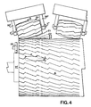
- Figure 4 is a substantially symbolic, front view of caricatured positions.
- the knurling tool is shown with an exaggerated barrel-like shape with regard to a roll being engraved.
- On the right side of Figure 4, the knurling tool is shown already fed by more angular and longitudinal pitches, and is in the final rolling step.
- Figure 4 shows both the barrel-like shape which, in practice, is included in a range between Z1 and Z4, and 0,6 mm, of radius difference and rolling, as well as longitudinal and angular feeding.
- a machine for mechanical engraving rolls includes, conventionally, a lathe-like structure, including a frame 9.
- the frame 9 has guides 9', two boxes 9'', a head 90 having a gripping chuck 91, the gripping chuck 91 is driven by a motor 5, a pair of steady rests or supports 92, 92', a carriage 93, having an apron 94 mounted to the steady rests 92 and 92' and a screw 95 comprises the operative engraving unit.
- the operative engraving unit also includes a knurling tool 3 having four ranges of freedom (named as X, W, Y, Z) including a substantially radial movement (W) for approaching, which is caused by the action of a press 2.
- a D.C. motor 5 drives the gripping chuck or faceplate 91 to which the roll 4, to be worked is attached.
- the roll 4 turns around its axis.
- the D.C. motor 5 receives electrical power by means of cable 5' from the electric panel 7 and is controlled by a first encoder 50. Signals from the first encoder 50 are received through one or more wires 50' and these signals may be referred as present correct positions, of the roll 4 being worked.
- the present correct positions are also used to position, at least longitudinally the position of knurling tool 3.
- the four conventional ranges of freedom (X, W, Y, Z) and, in accordance with the present invention, the braking (Y') or unbraking of the knurling is characterized as follows. Longitudinal movement (X) of the carriage 93, on which the knurling tool unit 1 is mounted, is driven by a conventional screw 95 of a machine tool. However, knurling tool unit 1 is disassociated from the rest of the tool machine. and driven by motor 6, receiving electrical power by means D.C. cable 61'', and its position is determined by a second encoder 6'.
- the signals generated by the second encoder 6', referred to as correct present position, of knurling tool 3, with respect to roll 4 are transmitted, through one or more wires 61'.
- Limit switches 60, 60', connected to the electric panel, through cables 60'', 60''', may be placed at the ends 4', 4'' of roll 4 to be worked.
- the second range of freedom (W) of knurling tool 3, comprises a substantially radial and substantially vertical movement, for approaching and displacing it away from the roll 4 being worked.
- Such range of freedom (W) includes a base position, to be determined manually, only once.
- the base position is set by adjusting a screw 2' of press 2, to determine the utmost centripetal position, of angular extension.
- the press 2 is driven by a first class lever suspension, as is known which is powered by a fluidynamic or hydraulic cylinder-piston unit 20, according to the present invention.
- a fluidynamic or hydraulic cylinder-piston unit 20 is connected to a hydraulic station 21 and is controlled through a pair of electrovalves 22, 22'.
- the pair of electrovalves 22, 22' are in turn controlled by input signals coming through wires 22'', 22''', from electronic computerized circuit 7. Even this range of freedom (W) is limited by a limit switch 123, connected to the electronic computerized circuit 7 by wire 123'.
- the third range of freedom (Y) includes rotation of the knurling tool 3 on its projecting hubs 3', 3'' about its axis.
- the knurling tool 3 is substantially idle and rotation is induced by the roll 4. (This is named the Y axis.)
- the knurling tool 3 engages the roll 4 and therefore they will rotate (y1) at the same time.
- a temporary braking (Y') or fastening device 8 is operated to cover the time gap between removal and reengagement of the knurling tool 3.
- the fourth range of freedom is comprised by angular excursion (about the Z axis) of axis defined by the hubs 3', 3'', of knurling tool, about a fixed fulcrum 30.
- Generatrixs (03) Z1, Z2, Z3, Z4, of tangency, may take place by driving a system, as is known.
- the system includes a second class lever, which has, as power, a screw 30' loading a spring 30'' and as resistance a substantially bridge-like support 31, carrying knurling tool 3.
- Vertical positioning of knurling tool 3 is provided by extension of piston 20', within the fluidynamic cylinder 20 which provides the operating pressure.
- This range of freedom (Z) is used only when the pitch or ratio, of the design to be engraved, is greater than 4-5 cm, with a corresponding length of knurling tool 3 greater than 8 cm, and having a barrel-like shape 03.
- This range of freedom (Z) may possibly be needed during movements regarding the third range of freedom (Y) .
- Conventionally these ranges of freedom (X, W, Y, Z) were controlled manually, at least for driving and/or starting and/or adjusting and/or stopping.
- suitable means are provided, already described in part, to solve the specific problems.
- the lead screw 95 is driven by a permanent magnet motor 6.
- the permanent magnet motor 6 is powered by a D.C. cable 61''.
- the permanent magnet motor 6 is subjected to a tele-reverser, not shown, placed within electric panel 7.
- the lead screw 95 is coupled in an axial relationship with second encoder 6' whose input and output terminal 1', is connected to the electric and electronic panel 7.
- the excursion range of carriage 93 is limited by two limit switches 60, 60', also electrically connected, by wires 60'' and 60''', to the electric panel 7.
- second movement or range of freedom (W) instead of a manual device driver, not shown, which has been removed, an alternative fluidynamic motor 20, fed by a hydraulic station 21, is used.
- a pair of electrovalves 22, 22' have electrical wires 22'', 22''', connected thereto for controlling the second movement (W) .
- a duplicate of members, not shown, includes drivers 23, 23', controlled by electrovalve 24, connected by wire 24' to the electric panel 7 whereby the approaching pressure applied to fluidynamic motor 20 is provided with two different intensities: adjustably lower at the beginning and upon a certain time set on a timer 23'' connected to the electric panel 7 by wire 23''', a full pressure, which is adjustable too, once and for a certain time.
- the hydraulic station 21 drives also another device, to be described hereafter, substantially with reference to the third movement (Y) .
- the third movement or range of freedom (Y) includes the substitution of a conventional asynchronous three-phase motor, not shown, with a permanent magnet D.C. motor 5 which indirectly drives a roll gripping chuck 91.
- the driving of the roll is provided through a belt transmission 50'' and some gears, not shown.
- An first encoder 50 associated with this movement, monitors the real movements (y1) of roll 4 that is to be worked.
- the roll 4 is engaged by cylindrical surface 91', of gripping chuck 91.
- the gripping chuck 91 includes a dog-like driver 91'', substantially without clearance, both with respect to the hub 4''', of roll 4, to be worked and thus of the same roll, and with regard to leading disc 91.
- This third movement or range of freedom (Y) is very important, not only in itself, but since it determines the rotation of knurling tool 3.
- the rotation of the knurling tool is provided with hubs 3', 3'' idly mounted on respective supports 33', 33'', in a conventional manner.
- Such movement (Y) is induced, in fact it is provided by the engagement (y1) of the knurling tool 3, which may be defined as toothed with the roll 4.
- a proper meshing is established, which obviates the provision of a reference mark on driver and transmission member, upstream of first encoder 50, engaged by gripping chuck 91 and on the disc itself.
- the first case is when the two members 3 and 4, providing the coupling, have to re-encounter in the same reciprocal angular position as when embossing a design having linear repetitivity.
- the second case is that the re-encounter happens to be on reciprocal different angular positions, dictated by longitudinal pitch P and by angular pitch p of a design with worm or angular repetitivity (Fig. 4).
- a substantial absence of movement of roll 4 to be worked corresponds to absolute immobility of knurling tool 3.
- the hubs 3', 3'' of knurling tool 3 are longer than conventional ones.
- the hubs 3', 3'' extend outward from supports 33', 33'', in order to be engaged by a pair of brake shoes 34, 34'.
- the brake shoes 34, 34' are driven by fluidynamic motors 35, controlled by electrovalves 24 and fed by the same hydraulic station 21, providing the pressure for the second movement (W) .
- the absolute immobility of knurling tool 3, obtained in the same manner, is made so that a movement (y1) of the roll 4 corresponding with an angular movement p, controlled by first encoder 50 can be made.
- the automatic lubricating system 13 provides lubricant to the hubs 3' and 3'', of knurling tool 3.
- Such lubricating system is automatic and has varied lubrication methods, i.e. by soaking, and with timed forced injections.
- the kinematic device 31 includes a reaction spring 30''.
- the screw 30' was provided with a member 36, driven by a geared transmission.
- the geared transmission is driven by a complementary member 36', driven by a permanent magnet D.C.motor 36''.
- Permanent magnet D.C. motor 36'' has power supplied to it through wire 36'''.
- the third encoder 37 is connected to electric panel 7 by cable 37' and is axially coupled to the screw 30'.
- a pair of angular limit switchs 38, 38', connected to electrical panel by cables 38'' and 38''' is also placed on the screw 30'.
- the screw pitch is such to maintain the excursion within an angle less than 360°.
- example I shows a roll including a design of the kind not employing all the resources of the system.
- example II expressly referring to Figure 4, thoroughly uses all the system resources.
- the program is roughly described which is suitably provided and that, opportunely simplified may be used to program also example I.
- carriage 93 carrying the engraving operative unit 1, is conventionally placed at the end 4' of roll 4.
- the knurling tool 3 On the same unit, is mounted the knurling tool 3, in a conventional manner.
- a suitable bracket not shown, may be put on or removed.
- Braking shoes 34 are provided, which are temporarily released and removed, in a way to be explained later on.
- the position of knurling tool 3 is set, the mounting is checked and corrected, with a suitable adjusting screw.
- the hydraulic station 21, is started.
- the hydraulic station provides a lower pressure, at least in cylinder 20, at least to reach about 3 Kg/cm2(3 atmospheres).
- roll 4 is caused to rotate and pressure is gradually increased, to reach about 10, 12 Kg/cm2 (10, 12 atmospheres).
- the program is started for automatic prosecution of engraving, along the whole roll 4 or along part of it. Substantially no further operator's intervention is needed except for the final unloading of roll or possibly an intermediate stage to provide a corrosion step.
- the program for a determined roll 4 is programmed only once and may be used repeatedly to provide a single engraving from end to end.
- the program will be such to control the X, Y, Z axes, wherein control of Y axis involves the additional function of roll re-positioning.
- Roll re-positioning requires an angular excursion corresponding with drawing, along the whole length of roll 4 or on one part thereof. No further intervention is required by the operator, exception made for the final unloading of roll or possibly an intermediate stage to provide a corrosion step.
- the program for a determined roll 4, is programmed only once and may be repeatedly used to provide a single engraving from end to end. Repeating the engraving, requires an intervention of the operator, to return the carriage 93 with the engraving operative unit 1 to the end 4' of roll 4, (substantially, the starting condition).
- Other steps include checking and adjusting the matching between the knurling tool 3 and the already engraved track, as well as with program repetition.
- Figure 2 shows a numerical control, substantially comprising a central unit 70, including a microprocessor 71, EPROM memories 72, RAM memories 72', mathematic co-processor 73, serial interface 74, an analogical output 75, an input/output port 76, a digital output 76'.
- the central unit 70 is connected with nine modules: an input control module 77, an output control module 77', a console module 77'', an X positioning module 78, an X-counting module 178, a Y positioning module 78' a Y-counting module 178', a Z positioning module 78'', a Z counting module 178'', as well as power supply 79.
- the numerical control includes, in 101 the machine input, in 102x, 102y, 102z the on/off and reference, in 103 the miscellaneous output and in 104x, 104y, 104z the input for positional transducer encoder type.
- microprocessor 71 is of Z 80 or cdp 1802 type
- the EPROM memories 72 are of the 27512 type or of the 27256 type.
- the RAM memories 72' are static, of 6264 type, with back battery, the mathematics co-processor 73, is of AMD 9511 type and serial interface 74 is of RS232 C type.
- Numerical control has substantially the following characteristics. It controls three axes, displacement range is +/- 9999,99 mm, accelerations are programmable, circular interpolation on plane, linear interpolation on all axes, programming support with parametric instructions, reference point machine cycle. Programming is absolute and/or incremental and with host computer, DNC mode and teach. Programmable functions are as follow: miscellaneous functions (M), preparatory functions (G), feed function (F) for axes, spindle function (S), nesting subroutine, nesting loop functions and reference point translation thereof; complete security diagnostic continuous checking; auto-test with variable polling; machine transducer with continuous diagnostic; manually operable in two ways with continuous and adjustable of all the axes and by programmable single steps.
- M miscellaneous functions
- G preparatory functions
- F feed function
- S spindle function
- nesting subroutine nesting loop functions and reference point translation thereof
- complete security diagnostic continuous checking auto-test with variable polling
- machine transducer with continuous diagnostic manually oper
- the interface includes thirtytwo testable inputs, thirtytwo 24V, 100 mA, outputs + 24V, 1,2A, output; output stages are of open collector type with TR BD677 type or MJ 3001 type; working is tested by external gauges (reading in BCD code).
- memory (72) is of 64 Kbyte, expandable up to 256 Kbyte and RAM memory (72') is of 18 Kbyte expandable up to 50 Kbyte.
- the control console in Figure 5 comprises: a 270 LED display, to display the digits of x, y, z axes; of program block numbers, of the instructions given; display (271) by shifting; keyboard (272) with keys 0 to 9, keys + and - as well as keys for switching the function selector, as well as the delete key and keys start and stop; feed rate override (273) from 10% to 100%; mode selector (274) of the operation modes with the following positions:
- the program for engraving of roll 4, with the drawing of example II shown in Figure 4 is the following: 1)M24; 2)@t1; 3)M21; 4)@t2; 5)M23; 6)G91; 7)Zz1-z4; 8)@t3; 9)M83; 10@t4; 11)M22; 12)@t5; 13)M82; 14)@t6; 15)M81; 16)M84; 17)G91; 18)Zz4-z1; 19)G91; 20)XP; 21)G62; 22)M25; 23)Yp; 24)M85; 25)@t7; 26)JnP-1; 27)M99.
- Z indicates the extent of angular excursion that knurling tool 3 has to make in the time t3+t4+t5.
- J indicates the number of return to the program origin 1) before passing to instructions M99.
Landscapes
- Engineering & Computer Science (AREA)
- Mechanical Engineering (AREA)
- Physics & Mathematics (AREA)
- Geometry (AREA)
- Life Sciences & Earth Sciences (AREA)
- Agronomy & Crop Science (AREA)
- General Engineering & Computer Science (AREA)
- Bending Of Plates, Rods, And Pipes (AREA)
- Shaping Of Tube Ends By Bending Or Straightening (AREA)
Claims (12)
- Verfahren zum automatischen Anpassen von wenigstens zwei sich abwälzenden und/oder pendelnden zylindrischen Flächen (3; 03-4), die eines Kordierwerkzeuges (3) und die einer zu gravierenden Walze (4), zum gegenseitigen Angriff zwecks mechanischer Prägegravierung einer Walze (4) mit einem Gravierwerkzeug (3) unter Verwendung von Freiheitsbereichen (X, W, Y, Z) eines Kordierwerkzeuges (3) wobei das Verfahren Start-, Wiederhol- und Endstufen beinhaltet, dadurch gekenn-zeichnet, daß es folgende Stufen umfaßt:
Annäherung und Anstellen (W) der Walze (4) an das Kordierwerkzeug (3), welches ein vorbestimmtes Muster für einen ersten Prägeeingriff aufweist:
Betätigung (yO) eines Motors (5), um die Walze (4) in einer Vorwärtsdrehrichtung und das Kordierwerkzeug (3) in Drehung zu versetzen (y₁), wobei das Kordierwerkzeug (3) das genannte vorbestimmte Muster auf der Walze (4) kordiert (Y);
Anhalten der Walze (4) nach einer vorbestimmten Winkelumdrehung (y₁) der Walze (4);
Wegschwenken (W) des Kordierwerkzeugs (3) von der Walze (4):
Verschieben (X) des das Kordierwerkzeug (3) tragenden Schlittens (93) linear um einen vorbestimmten Abstand in bezug auf den ersten Prägeeingriff des Kordierwerkzeuges (3);
durch Drehung Einstellen (Z) der Walze (4), um das Muster auf dem Kordierwerkzeug (3) auf das auf der Walze (4) eingravierte Muster aufzupassen; und
Wiederholung der Stufen der Annäherung (W), des Betätigens eines Motors, des Anhaltens der Walze (4), Absetzens (W) des Kordierwerkzeugs (3), Verschiebens (X) des das Kordierwerkzeug (3), tragenden Schlittens (93) und Einstellens einer vorbestimmten Anzahl von Maßen, bis ein gewünschter Abschnitt der Walze (4) graviert ist. - Verfahren nach Anspruch 1, gekennzeichnet durch die weiteren Stufen:
Anordnung einer zu bearbeitenden Walze (4);
Verschieben des Kordierwerkzeugs (3), welches Kordierwerkzeug (3) vier Freiheitsbereiche (X, W, Y, Z) aufweist, mittels eines Druckorgans (2) zur radialen Anstellung an die Walze (4);
Drehen der Walze (4) mit einem ersten Gleichstrommotor (5), wobei der Gleichstrommotor (5) durch einen ersten Kodierer (50) gesteuert wird. - Verfahren nach Anspruch 1, dadurch gekennzeichnet, daß die Steuerungsstufe die Stufe der Abbremsung (Y') des Kordierwerkzeuges (3) zwischen jeder Schwenk-Wiederholungsstufe (W) umfaßt, um ein Muster (03) im Kordierwerkzeug (3) fluchtend mit einem auf der Walze (4) eingravierten Muster aufrecht zu erhalten.
- Verfahren nach Anspruch 2, gekennzeichnet durch die weiteren Stufen:
Steuerung der vier Freiheitsbereiche (X, W, Y, Z,) und der Abbremsung (Y'), um die Drehung (Y) des Kordierwerkzeugs (3) zu verhindern, wenn es von der Walze (4) abgesetzt wird. - Verfahren nach Anspruch 4, dadurch gekennzeichnet, daß die Stufe der Steuerung der vier Freiheitsbereiche (X, W, Y, Z,) eine Stufe der Steuerung eines ersten Freiheitsbereiches (X) umfaßt, wobei die Steuerung einer ersten Freiheitsstufe (X) die Stufen umfaßt: Verschiebung (X) in Längsrichtung eines Schlittens (93), auf dem das Kordierwerkzeug (3) montiert ist, wobei der Schlitten (93) durch eine unabhängig von einem zweiten Gleichstrommotor (6) in Drehung versetzte Schraube (95) angetrieben wird; und
Steuerung der Lage des Schlittens (93) in bezug auf die Walze (4) in Antwort auf Signale, die von einem zweiten Kodierer (6'), der an die Schraube (95) angeschlossen ist, und durch Begrenzungsschalter (60, 60'), die an den Enden (4', 4'') der zu bearbeitenden Walze (4) montiert sind, um die Verschiebung des Schlittens (93) durch den zweiten Gleichstrommotor (6) zu begrenzen, erzeugt werden. - Verfahren nach Anspruch 5, dadurch gekennzeichnet, daß die Stufe der Steuerung der vier Freiheitsbereiche (X, W, Y, Z,) die Stufe der Steuerung eines zweiten Freiheitsbereiches (W) umfaßt, wobei die Stufe einer zweiten Freiheitsstufe (W) die Stufen umfaßt:
Annäherung und Absetzung des Kordierwerkzeuges (3) von der zu bearbeitenden Walze (4) in einer im wesentlichen radialen, im wesentlichen vertikalen Richtung, wobei der zweite Freiheitsbereich (W) eine manuell betätigbare Einstellschraube (2') zur Festlegung einer einmal festzulegenden Basisstelle umfaßt, wobei das Verfahren die Stufe der manuellen Adjustierung der manuell betätigbaren Einstellschraube (2') umfaßt, um die erwähnte Basisstelle für einen Winkelausschlag festzulegen, welcher von einer Aufhängung in Form eines Hebels erster Klasse (2', 31, 3) herbeigefuhrt wird, wobei der Winkelausschlag durch eine prieumatische oder hydraulische Zylinder-Kolben-Einheit (20) durch Elektroventile (22, 22'), die durch von einem computerisierten elektronischen System (7) ankommende Signale gesteuert werden, erzeugt wird, wobei der genannte zweite Freiheitsbereich (W) durch einen Begrenzungsschalter (123) begrenzt wird. - Verfahren nach Anspruch 6, dadurch gekennzeichnet, daß die Stufe der Steuerung eines zweiten Freiheitsbereiches (W) den genannten hydraulischen Zylinder-Kolbens (20) mit zwei unterschiedlichen Stärkegraden vorsieht, wobei einer der beiden unterschiedlichen Stärkegrade am Anfang geringer und nach einer gewissen, auf einem Zeitgeber (23'') eingestellten Zeit, der zweite dieser zwei unterschiedlichen Stärkegrade ein Volldruck ist.
- Verfahren nach Anspruch 4, dadurch gekennzeichnet, daß die Stufe der Steuerung der vier Freiheitsbereiche (X, W, Y, Z,) weiters die Stufe der Steuerung eines dritten Freiheitsbereiches (Y) umfaßt, wobei die Stufe der Steuerung des dritten Freiheitsbereiches (Y) die Stufen umfaßt:
Veranlassen (y₁) daß das Kordierwerkzeug (3), um seine Achse rotiert, indem das Kordierwerkzeug (3) mit der zu bearbeitenden Walze (4) in Eingriff gebracht und das Kordierwerkzeug (3) vorübergehend im Zeitintervall zwischen der Absetzung und Annäherung (W) des Kordierwerkzeuges (3) an die Walze (4) in Übereinstimmung mit dem zweiten Freiheitsbereich (W), zugeordnet zu jeder Längsverschiebung (X) des Schlittens (93) in Übereinstimmung mit dem ersten Freiheitsbereich (X), abgebremst wird (y'). - Verfahren nach Anspruch 4, dadurch gekennzeichnet, daß die Stufe der Steuerung der vier Freiheitsbereiche (X, W, Y, Z,) die Steuerung eines dritten Freiheitsbereiches (Y) umfaßt, wobei die Steuerung des dritten Freiheitsbereiches (Y) die Stufen der Steuerung eines Permanentmagnet-Gleichstrommotors (5) für den indirekten Antrieb eines Walzen-Einspannkopfs (91) umfaßt, wobei dieser indirekte Antrieb (yO) durch einen Riementrieb (50'') und wenigstens zwei Zahnräder geschaffen wird, wobei ein erster, der Bewegung (y₁) des Walzen-Einspannkopfs (91) zugeordneter Kodierer (50) die tatsächlichen Bewegungen (y₁) der zu bearbeitenden Walze (4) überwacht, der erste Kodierer (50) im Eingriff mit einer zylindrischen Flache (91') steht und der Walzen-Einspannkopfs eine Mitnehmerklaue (91'') im wesentlichen ohne Spiel in bezug auf die Nabe (4''') der zu bearbeitenden Walze (4) und somit in bezug auf die Führungsscheibe (91) umfaßt.
- Verfahren nach Anspruch 4, dadurch gekennzeichnet, daß die Steuerungsstufe eine Stufe der Steuerung eines vierten Freiheitsbereiches (Z) umfaßt, wobei die Stufe der Steuerung eines vierten Freiheitsbereiches (Z) die Stufe des Wiedereingriffes des Kordierwerkzeuges (3) mit der Walze (4) bei verschiedenen gegenseitigen Stellungen (Z₁, Z₂, Z₃, Z₄) umfaßt.
- Verfahren nach Anspruch 3, dadurch gekennzeichnet, daß der vierte Freiheitsbereich (Z) durch deine Schraube (30') geschaffen wird, die eine aus einer Abreißfeder (30''), bestehend kinematische Vorrichtung, umfaßt wobei der vierte Freiheitsbereich (Z) mechanisiert ist, indem die Schraube (30') mit einem Teil (36) versehen ist, der durch einen komplementären Teil (36') angetrieben wird, welcher durch einen Permanentmagnet-Gleichstrommotor (36'') angetrieben wird, und wobei ein dritter Kodierer (37) axial an die Schraube (30') gekuppelt ist und Zwei Winkelbegrenzungsschalter (38, 38') die Drehung der Schraube (30') begrenzen, welche Winkelbegrenzungsschalter (38, 38') den Weg der Schraube (30') in einem Winkel von weniger als 360º begrenzen.
- Eine Maschine zum automatischen Anpassen von wenigstens zwei sich abwälzenden und/oder pendelnden zylindrischen Flächen (3; 03-4), die eines Kordierwerkzeuges (3) und die einer zu gravierenden Walze (4) zum gegenseitigen Angriff zwecks mechanischer Prägegravierung einer Walze (4), wobei die Maschine umfaßt:
eine Halterungsstruktur für die Walze (4) zur Drehung derselben darauf um eine Drehachse (y₁);
Einrichtungen zur Drehung der Walze (4) um die genannte Drehachse (y₁);
einen auf der genannten Struktur beweglich montierten Schlitten (93), welcher Schlitten (93) in einer Richtung (X) parallel zur genannten Drehachse (y₁) der Walze (4) bewegbar ist;
ein drehbar auf einem Paar von Halterungen montiertes Kordierwerkzeug (3), wobei das Paar von Halterungen bewegbar am Schlitten (93) montiert und das Kordierwerkzeug (3) in Antwort auf die Drehung der Walze (4) drehbar ist, wenn sich das Kordierwerkzeug (3) im Eingriff mit der Walze (4) befindet;
Einrichtungen (2) zur Schwenkbewegung (W) des Kordierwerkzeuges (3) in Eingriff und außer Eingriff mit der Walze (4);
Einrichtungen (35) zur axialen Verschiebung (X) des Schlittens (93) über eine vorbestimmte Distanz; und
Einrichtungen (7) für die elektronische Steuerung des Betriebes der Maschine umfassed die Steuerung der Einrichtungen für die Schwenkbewegung (W) des Kordierwerkzeugs (3), der Einrichtungen für die axiale Verschiebung des Schlittens (93), wobei die Einrichtungen zur elektronischen Steuerung aufeinanderfolgend den Betrieb der Maschine über wiederholbare Sequenzen fortschreitend entlang der Walze (4) steuern.
Priority Applications (1)
| Application Number | Priority Date | Filing Date | Title |
|---|---|---|---|
| AT89900814T ATE111036T1 (de) | 1988-12-13 | 1988-12-13 | Verfahren und vorrichtung zum automatischen übereinstimmen von mindestens zwei kongruenten zylindrischen flächen, insbesondere zum mechanischen eingravieren. |
Applications Claiming Priority (1)
| Application Number | Priority Date | Filing Date | Title |
|---|---|---|---|
| PCT/EP1988/001150 WO1990006856A1 (en) | 1988-12-13 | 1988-12-13 | Process and means for automatically matching at least two substantially cylindrical surfaces, engaging each other, particularly for mechanical emboss engraving, and engraved plates obtained with such process and means |
Publications (2)
| Publication Number | Publication Date |
|---|---|
| EP0408560A1 EP0408560A1 (de) | 1991-01-23 |
| EP0408560B1 true EP0408560B1 (de) | 1994-09-07 |
Family
ID=8165354
Family Applications (1)
| Application Number | Title | Priority Date | Filing Date |
|---|---|---|---|
| EP89900814A Expired - Lifetime EP0408560B1 (de) | 1988-12-13 | 1988-12-13 | Verfahren und Vorrichtung zum automatischen Übereinstimmen von mindestens zwei kongruenten zylindrischen Flächen, insbesondere zum mechanischen Eingravieren |
Country Status (4)
| Country | Link |
|---|---|
| US (1) | US5197317A (de) |
| EP (1) | EP0408560B1 (de) |
| DE (1) | DE3851441T2 (de) |
| WO (1) | WO1990006856A1 (de) |
Families Citing this family (13)
| Publication number | Priority date | Publication date | Assignee | Title |
|---|---|---|---|---|
| JP3804871B2 (ja) * | 1995-10-05 | 2006-08-02 | スリーエム カンパニー | ワークピースにローレットを形成する方法および装置、当該ワークピースを使って製品を成形する方法、並びに当該成形製品 |
| US5975987A (en) * | 1995-10-05 | 1999-11-02 | 3M Innovative Properties Company | Method and apparatus for knurling a workpiece, method of molding an article with such workpiece, and such molded article |
| US5771796A (en) * | 1996-10-29 | 1998-06-30 | Microfibres, Inc. | Embossing cylinder for embossing pile fabric |
| US5946991A (en) * | 1997-09-03 | 1999-09-07 | 3M Innovative Properties Company | Method for knurling a workpiece |
| US6846172B2 (en) * | 2002-06-07 | 2005-01-25 | The Procter & Gamble Company | Embossing apparatus |
| DE20312485U1 (de) * | 2003-03-04 | 2003-10-16 | Langenstein & Schemann Gmbh, 96450 Coburg | Walzmaschine zum Umformen eines Werkstücks |
| US20050011244A1 (en) * | 2003-07-15 | 2005-01-20 | Hampton Daniel Riley | Roller rocker |
| CN101212876A (zh) * | 2006-12-29 | 2008-07-02 | 深圳富泰宏精密工业有限公司 | 金属外壳及其制作方法 |
| CN101628370B (zh) * | 2009-06-05 | 2013-04-10 | 滕州市三合机械股份有限公司 | 滚压成型机 |
| KR101411068B1 (ko) * | 2012-12-17 | 2014-06-25 | 권석화 | 공작물 너얼링 절삭 가공 장치 |
| CN104742631B (zh) * | 2015-03-09 | 2017-11-24 | 卢玉兰 | 插花分离组件 |
| US10493518B2 (en) * | 2016-08-30 | 2019-12-03 | Otis Elevator Company | Sheave knurling tool and method of operating |
| EP3983690B1 (de) * | 2019-06-14 | 2025-07-30 | GKN Driveline Deutschland GmbH | Verfahren zur herstellung einer verzahnung und bauteil einer wellen-/nabenverbindung |
Family Cites Families (12)
| Publication number | Priority date | Publication date | Assignee | Title |
|---|---|---|---|---|
| DE218759C (de) * | ||||
| DE29403C (de) * | J. MÜLLER in Zarewo bei Moskau | Molettirmaschine | ||
| FR723251A (fr) * | 1930-10-13 | 1932-04-06 | Keller Dorian Colorfilm Corp | Méthode et appareil à graver les cylindres pour le gaufrage des films |
| DE760320C (de) * | 1937-03-17 | 1953-10-05 | Dornbusch & Co | Verfahren und Vorrichtung zur Herstellung von Praegekoerpern, insbesondere Musterungswalzen |
| US3292403A (en) * | 1962-10-22 | 1966-12-20 | Modern Engraving And Machine C | Embossing mill registration locking device |
| US3537287A (en) * | 1969-02-07 | 1970-11-03 | Albert Schwartz | Tube configuring machine |
| US3827334A (en) * | 1971-05-07 | 1974-08-06 | Remington Arms Co Inc | Numerically controlled engraving machine system |
| US3987350A (en) * | 1971-05-18 | 1976-10-19 | Ing. C. Olivetti & C., S.P.A. | Numerical control system for center lathes |
| FR2288627A1 (fr) * | 1974-08-22 | 1976-05-21 | Remington Arms Co Inc | Systeme de reproduction automatique de motifs geometriques, notamment pour le quadrillage des parties en bois des armes a feu |
| IT1115651B (it) * | 1977-04-21 | 1986-02-03 | Bottega Incisioni | Dispositivo per incidere a settori elementi metallici,particolarmente per parti di armi |
| DE2724664C3 (de) * | 1977-06-01 | 1982-01-21 | Reishauer AG, 8000 Zürich | Einrichtung zur Erzeugung einer Zusatzdrehbewegung eines schrägverzahnten Zahnrad-Werkstücks in einer zwangslaufgesteuerten, nach dem Schraubwälzverfahren arbeitenden Zahnrad-Bearbeitungsmaschine |
| GB2002694B (en) * | 1977-08-16 | 1982-02-17 | Rolls Royce | Mpu controlled engraving machine |
-
1988
- 1988-12-13 EP EP89900814A patent/EP0408560B1/de not_active Expired - Lifetime
- 1988-12-13 DE DE3851441T patent/DE3851441T2/de not_active Expired - Lifetime
- 1988-12-13 WO PCT/EP1988/001150 patent/WO1990006856A1/en not_active Ceased
- 1988-12-13 US US07/572,995 patent/US5197317A/en not_active Expired - Lifetime
Also Published As
| Publication number | Publication date |
|---|---|
| DE3851441T2 (de) | 1995-05-04 |
| EP0408560A1 (de) | 1991-01-23 |
| DE3851441D1 (de) | 1994-10-13 |
| US5197317A (en) | 1993-03-30 |
| WO1990006856A1 (en) | 1990-06-28 |
Similar Documents
| Publication | Publication Date | Title |
|---|---|---|
| EP0408560B1 (de) | Verfahren und Vorrichtung zum automatischen Übereinstimmen von mindestens zwei kongruenten zylindrischen Flächen, insbesondere zum mechanischen Eingravieren | |
| RU2091191C1 (ru) | Способ формирования изделий из металлической проволоки, станок для формирования изделий из металлической проволоки, установка для формирования изделий из проволоки, рабочий инструмент для станка для формирования изделий из проволоки, сменное приводное устройство для инструмента | |
| CN105014439A (zh) | 第四、五轴夹具 | |
| CN1023667C (zh) | 控制一个机床(例如一个车床)的方法和系统 | |
| US5050468A (en) | Method and apparatus for cutting a circumferential serpentine groove in a workpiece using an engine lathe | |
| EP0083304B1 (de) | Maschine mit einem intermittierend rotierenden Tisch zur Bearbeitung und Montage von hoch präzisen Teilen | |
| US4926709A (en) | Motion transmitting systems for machinery & machine tools | |
| CN217666577U (zh) | 一种电机端盖打孔装置用同轴度调整结构 | |
| CN204771736U (zh) | 一种多工位气动夹具 | |
| CN222857371U (zh) | 一种带有自动定位功能的数控机床固定夹具 | |
| EP0437176B1 (de) | Maschine mit schrittweise drehendem Werkstücktisch für Bearbeitung und Montage an hochpräzisen Werkstücken | |
| CN204893496U (zh) | 第四、五轴夹具 | |
| JPH03178720A (ja) | 歯車のラップ仕上げ方法 | |
| JP2641303B2 (ja) | 歯車の歯形整形装置 | |
| JPH0448533B2 (de) | ||
| JPH0448532B2 (de) | ||
| JPH0430943A (ja) | 工作機械の割出刃物台 | |
| GB1474159A (en) | Gear grinding machine | |
| RU2068754C1 (ru) | Станок для шевингования - прикатывания зубчатых колес | |
| US4050274A (en) | Apparatus for forming grooved wheels | |
| CN218746379U (zh) | 可旋转工件铣床工装 | |
| CN222429964U (zh) | 一种数控机床马达座结构 | |
| GB1536831A (en) | Method and machine for machining the tooth ends of gearwheels | |
| JPS60249525A (ja) | 歯車加工機の被加工歯車かみ合わせ装置 | |
| JPH06238516A (ja) | 歯車の面取り装置 |
Legal Events
| Date | Code | Title | Description |
|---|---|---|---|
| PUAI | Public reference made under article 153(3) epc to a published international application that has entered the european phase |
Free format text: ORIGINAL CODE: 0009012 |
|
| AK | Designated contracting states |
Kind code of ref document: A1 Designated state(s): AT BE CH DE FR GB IT LI LU NL SE |
|
| 17P | Request for examination filed |
Effective date: 19910326 |
|
| 17Q | First examination report despatched |
Effective date: 19930212 |
|
| GRAA | (expected) grant |
Free format text: ORIGINAL CODE: 0009210 |
|
| AK | Designated contracting states |
Kind code of ref document: B1 Designated state(s): AT BE CH DE FR GB IT LI LU NL SE |
|
| REF | Corresponds to: |
Ref document number: 111036 Country of ref document: AT Date of ref document: 19940915 Kind code of ref document: T |
|
| ITF | It: translation for a ep patent filed | ||
| REF | Corresponds to: |
Ref document number: 3851441 Country of ref document: DE Date of ref document: 19941013 |
|
| PG25 | Lapsed in a contracting state [announced via postgrant information from national office to epo] |
Ref country code: SE Effective date: 19941207 |
|
| ET | Fr: translation filed | ||
| PLBE | No opposition filed within time limit |
Free format text: ORIGINAL CODE: 0009261 |
|
| STAA | Information on the status of an ep patent application or granted ep patent |
Free format text: STATUS: NO OPPOSITION FILED WITHIN TIME LIMIT |
|
| 26N | No opposition filed | ||
| REG | Reference to a national code |
Ref country code: GB Ref legal event code: IF02 |
|
| PGFP | Annual fee paid to national office [announced via postgrant information from national office to epo] |
Ref country code: LU Payment date: 20071205 Year of fee payment: 20 Ref country code: NL Payment date: 20071227 Year of fee payment: 20 |
|
| PGFP | Annual fee paid to national office [announced via postgrant information from national office to epo] |
Ref country code: AT Payment date: 20071127 Year of fee payment: 20 Ref country code: IT Payment date: 20071127 Year of fee payment: 20 Ref country code: CH Payment date: 20071219 Year of fee payment: 20 |
|
| PGFP | Annual fee paid to national office [announced via postgrant information from national office to epo] |
Ref country code: BE Payment date: 20071217 Year of fee payment: 20 |
|
| PGFP | Annual fee paid to national office [announced via postgrant information from national office to epo] |
Ref country code: GB Payment date: 20071220 Year of fee payment: 20 |
|
| PGFP | Annual fee paid to national office [announced via postgrant information from national office to epo] |
Ref country code: DE Payment date: 20080220 Year of fee payment: 20 |
|
| PGFP | Annual fee paid to national office [announced via postgrant information from national office to epo] |
Ref country code: FR Payment date: 20071227 Year of fee payment: 20 |
|
| REG | Reference to a national code |
Ref country code: CH Ref legal event code: PL |
|
| BE20 | Be: patent expired |
Owner name: *DELLA TORRE RENATO Effective date: 20081213 |
|
| REG | Reference to a national code |
Ref country code: GB Ref legal event code: PE20 Expiry date: 20081212 |
|
| PG25 | Lapsed in a contracting state [announced via postgrant information from national office to epo] |
Ref country code: NL Free format text: LAPSE BECAUSE OF EXPIRATION OF PROTECTION Effective date: 20081213 |
|
| PG25 | Lapsed in a contracting state [announced via postgrant information from national office to epo] |
Ref country code: GB Free format text: LAPSE BECAUSE OF EXPIRATION OF PROTECTION Effective date: 20081212 |