EP0408791B1 - Pompe à effet visqueux à rotor en forme de cloche - Google Patents
Pompe à effet visqueux à rotor en forme de cloche Download PDFInfo
- Publication number
- EP0408791B1 EP0408791B1 EP89113317A EP89113317A EP0408791B1 EP 0408791 B1 EP0408791 B1 EP 0408791B1 EP 89113317 A EP89113317 A EP 89113317A EP 89113317 A EP89113317 A EP 89113317A EP 0408791 B1 EP0408791 B1 EP 0408791B1
- Authority
- EP
- European Patent Office
- Prior art keywords
- rotor
- housing part
- pump according
- cylindrical section
- bell
- Prior art date
- Legal status (The legal status is an assumption and is not a legal conclusion. Google has not performed a legal analysis and makes no representation as to the accuracy of the status listed.)
- Expired - Lifetime
Links
- 238000003860 storage Methods 0.000 claims description 6
- 238000007789 sealing Methods 0.000 claims description 3
- 238000011010 flushing procedure Methods 0.000 claims description 2
- 239000007789 gas Substances 0.000 description 17
- 239000000428 dust Substances 0.000 description 6
- 239000007787 solid Substances 0.000 description 6
- 239000003921 oil Substances 0.000 description 5
- 230000015572 biosynthetic process Effects 0.000 description 4
- 238000000034 method Methods 0.000 description 4
- 239000002245 particle Substances 0.000 description 4
- 238000010926 purge Methods 0.000 description 3
- NLXLAEXVIDQMFP-UHFFFAOYSA-N Ammonia chloride Chemical compound [NH4+].[Cl-] NLXLAEXVIDQMFP-UHFFFAOYSA-N 0.000 description 2
- XKRFYHLGVUSROY-UHFFFAOYSA-N Argon Chemical compound [Ar] XKRFYHLGVUSROY-UHFFFAOYSA-N 0.000 description 2
- IJGRMHOSHXDMSA-UHFFFAOYSA-N Atomic nitrogen Chemical compound N#N IJGRMHOSHXDMSA-UHFFFAOYSA-N 0.000 description 2
- XAGFODPZIPBFFR-UHFFFAOYSA-N aluminium Chemical compound [Al] XAGFODPZIPBFFR-UHFFFAOYSA-N 0.000 description 2
- 229910052782 aluminium Inorganic materials 0.000 description 2
- VSCWAEJMTAWNJL-UHFFFAOYSA-K aluminium trichloride Chemical compound Cl[Al](Cl)Cl VSCWAEJMTAWNJL-UHFFFAOYSA-K 0.000 description 2
- 238000000576 coating method Methods 0.000 description 2
- 230000007547 defect Effects 0.000 description 2
- 238000005530 etching Methods 0.000 description 2
- 235000019270 ammonium chloride Nutrition 0.000 description 1
- 229910052786 argon Inorganic materials 0.000 description 1
- 238000004140 cleaning Methods 0.000 description 1
- 239000011248 coating agent Substances 0.000 description 1
- 230000006835 compression Effects 0.000 description 1
- 238000007906 compression Methods 0.000 description 1
- 238000010276 construction Methods 0.000 description 1
- 238000011109 contamination Methods 0.000 description 1
- 238000010438 heat treatment Methods 0.000 description 1
- 239000011261 inert gas Substances 0.000 description 1
- 238000009434 installation Methods 0.000 description 1
- 239000000314 lubricant Substances 0.000 description 1
- 239000010687 lubricating oil Substances 0.000 description 1
- 238000012423 maintenance Methods 0.000 description 1
- 238000004519 manufacturing process Methods 0.000 description 1
- 229910052757 nitrogen Inorganic materials 0.000 description 1
- 230000002028 premature Effects 0.000 description 1
- 238000005086 pumping Methods 0.000 description 1
- 230000000630 rising effect Effects 0.000 description 1
- 238000005096 rolling process Methods 0.000 description 1
- 230000008646 thermal stress Effects 0.000 description 1
- 238000009489 vacuum treatment Methods 0.000 description 1
Images

Classifications
-
- F—MECHANICAL ENGINEERING; LIGHTING; HEATING; WEAPONS; BLASTING
- F04—POSITIVE - DISPLACEMENT MACHINES FOR LIQUIDS; PUMPS FOR LIQUIDS OR ELASTIC FLUIDS
- F04D—NON-POSITIVE-DISPLACEMENT PUMPS
- F04D19/00—Axial-flow pumps
- F04D19/02—Multi-stage pumps
- F04D19/04—Multi-stage pumps specially adapted to the production of a high vacuum, e.g. molecular pumps
- F04D19/044—Holweck-type pumps
-
- F—MECHANICAL ENGINEERING; LIGHTING; HEATING; WEAPONS; BLASTING
- F04—POSITIVE - DISPLACEMENT MACHINES FOR LIQUIDS; PUMPS FOR LIQUIDS OR ELASTIC FLUIDS
- F04D—NON-POSITIVE-DISPLACEMENT PUMPS
- F04D29/00—Details, component parts, or accessories
- F04D29/60—Mounting; Assembling; Disassembling
- F04D29/64—Mounting; Assembling; Disassembling of axial pumps
- F04D29/644—Mounting; Assembling; Disassembling of axial pumps especially adapted for elastic fluid pumps
Definitions
- the invention relates to a friction pump with the features of the preamble of claim 1.
- Friction pumps include molecular and turbomolecular pumps.
- a moving rotor wall and a stationary stator wall are designed and spaced such that the pulses transmitted from the walls to gas molecules located between them have a preferred direction.
- the rotor and / or stator wall are equipped with thread-like depressions or projections.
- Turbomolecular pumps have interlocking rows of stator and rotor blades in the manner of a turbine. You need a backing pressure of about 10 ⁇ 2 mbar. In contrast, molecular pumps deliver pressures of up to 10 mbar and more, so that the effort required for generating the forevacuum is considerably less.
- Friction pumps of the type mentioned at the outset are often used for evacuating chambers in which etching, coating or other vacuum treatment or manufacturing processes are carried out. These processes run the risk of solids getting into the pump. In some processes there is even the possibility that such solids only arise during the compression of the gases, that is, during the passage of the gases to be pumped through the vacuum chamber. Examples are the formation of aluminum chloride in aluminum etching, ammonium chloride in coating processes, etc.
- the present invention is based on the object the task of designing a friction pump of the type mentioned in such a way that the assembly work required for cleaning the gas delivery channels can be carried out simply and quickly. On the other hand, the risk of contamination of the bearings should be largely eliminated. Finally, the construction of the friction pump should enable measures to prevent the formation of dusts within the gas delivery channels.
- the pump-active surfaces inside of the stator or first housing part, outside of the rotor
- the pump-active surfaces are freely accessible and can be cleaned in a simple manner, preferably on site.
- this unit can only be replaced on site.
- the vacuum pump is ready for operation again.
- the defects found on the unit can be remedied by the manufacturer. Complex installation and commissioning measures, such as balancing processes, no longer have to be carried out at the customer's.
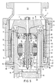
- All of the friction pumps 1 shown in the figures have a first housing part 2.
- Part of this first housing part 2 is the outer cylinder 3, which is equipped with the flange 4.
- the friction pump 1 is connected to the recipient to be evacuated either directly or via an attachment flange 5 (only shown in FIG. 5).
- the friction pumps according to FIGS. 1 to 5 have a second housing part 6, which serves to hold the rotor 7 and the stator of the drive motor 8.
- the rotor 7 is bell-shaped. It comprises the hub part 9 and the cylindrical section 10.
- the second housing part 6 projects into the space 11 formed by the bell-shaped rotor 7, in which the Drive motor 8 and at least the upper bearing of the two rotor bearings 12 is located.
- the outside of the rotor 7, together with the inside of the outer cylinder 3, forms the pump-active surfaces or the annular gas delivery channel 20.
- the gases to be pumped are conveyed from the inlet 13 to the outlet 14.
- a forevacuum pump, not shown, is connected to the outlet 14 during operation.
- the two housing parts 2 and 6 are designed such that they can be separated and joined together in a simple manner.
- a locking ring 15 serves to lock each other in the assembled state.
- the rotor 7 is each equipped with a central shaft 16 which is supported in the bearings 12.
- the bearings 12 are in turn supported by ring disks in a cylindrical section 17 which is part of the second housing part 6.
- the first housing part 2 has an inner cylindrical section 18 which directly surrounds the cylindrical section 17 of the second housing part 6.
- the cylindrical section 17 is equipped with an edge 19 which rests on the upper end face of the cylindrical section 18.
- the cylindrical section 17 protrudes downward from the cylindrical section 18 or the first housing part 2, so that there is the possibility of locking the two housing parts 2 and 6 against one another with the aid of the clamping ring 15. After loosening the clamping ring 15, the unit consisting of the rotor 7 and the second housing part 6 can be pulled up out of the first housing part 2.
- the first housing part 2 consists of the cylindrical section 3, which is equipped with an outwardly directed step 21 in the lower region.
- the second housing part 6 has a corresponding gradation 22.
- the lower edge of the housing part 2 protrudes from the Housing part 6 slightly so that there is again the possibility of locking ring locking. After loosening the clamping ring 15, the unit comprising the housing part 6 and the rotor 7 can be pulled down out of the housing part 2.
- the rotor 7 is supported via an inner cylindrical section 23 and the bearings 12 on a fixed pin 24, which is part of the second housing part 6.
- a cylinder section 25 protrudes from below, which is also part of the second housing part 6. This creates a kind of labyrinth seal, with the help of which the goal of preventing dust particles from entering the storage space is particularly well achieved.
- the drive motor 8 is designed as an external rotor motor. It can be arranged between the pin 24 and the cylinder section 23 (FIG. 3) or in the region of the lower edge of the bell-shaped rotor 7 (FIG. 4).
- means are used which comprise the clamping ring 15 and corresponding gradations 21, 22 (FIG. 4), as described for FIGS. 1 and 2.
- FIG. 5 shows that a lubricating oil supply for the bearings 12 of the shaft 16 is provided within the largely outwardly sealed space 11, formed by the rotor 7 and the housing part 6.
- the shaft 16 projects with a conical lower section 31 into an oil sump 32 and is equipped with a central oil channel 33.
- the oil rising in the central channel 33 reaches the bearings 12 via lateral bores 34 and 35 as a result of the centrifugal forces. These are supported via the annular disks 36 and 37 in the cylindrical section 17 of the housing part 6.
- the sealing of the space 11 to the rotor 7 serves a fitting 41 which is screwed to the upper area of the cylindrical section 17 (screws 42). Otherwise, this adapter 41 is adapted to the shape of the underside of the hub part 9 of the rotor 7 in such a way that a gap seal 43 results.
- This gap seal opens above the bearing 12.
- the upper bearing is equipped with an annular cover cap 44. This cap 44 is attached to the shaft 16 and covers the upper bearing 12.
- the components of the housing part 6 (cylinder 17, fitting 41, bottom 45 of the oil sump 32) are equipped with bores 46, 47 and 48, respectively, through which a flushing gas (inert gases such as nitrogen, argon, etc.) can be let into the space 11 .
- the purge gas passes through the gap seal 43 and through the gap (gap seal 48) formed between the inside of the cylindrical section 10 of the rotor 7 and the outside of the cylinder section 18 and reaches the outlet 14.
- a purge gas flow prevents gases laden with dust particles from entering reach the engine and storage room 11.
- a particular advantage is that the purge gas flow can also be maintained during the disassembly of the pump, so that the engine and storage space 11 is also protected from dust particles in this phase.
- the cylindrical section 10 of the rotor 7 has a relatively thin wall, so that the rotating mass is small.
- the threaded structures that produce the gases are part of the stator.
- the two rings 52 and 53 are equipped on their inner sides with threaded structures 56 and 57. Together with the outer surface of the cylinder section 10 of the rotor 7, these cause the gases to be conveyed in the direction of the outlet 14.
- the rings 51, 52, 53 are held in their position in the assembled state. After loosening the attachment flange 5, the rotor 7 and the housing part can first be removed 6 existing unit and then the rings 51, 52, 53 are removed upwards from the housing part 3.
- the ring 51 has a smooth inner surface.
- the structures 58 which produce the gases are provided on the rotor itself. For example, they can be designed as described in European patent application 88116749.8, i. H. radially extending webs are provided, the width and pitch of which decrease from the suction side to the pressure side. This results in an effective filling stage 51, 58 with improved delivery performance.
- the first housing part consists of the outer cylinder 3 and the inner cylinder 18. In the region of the outlet side 14, these cylinder sections 3, 18 have flange-like edges 61, 62 which are screwed together (screws 63).
- the housing part 6 protrudes downward from the housing part 2 and is equipped with a groove 64 for the clamping ring 15.
- a ring 65 surrounding the housing part 6 is provided, which is supported on the clamping ring 15. After assembly of the components, the ring 65 is pushed on and the clamping ring 15 is inserted into its groove 64. Securing the position of the components against one another is achieved with the aid of screws 66. These are guided in a thread in the ring 65. After complete assembly, the desired mutual position of the two components 2 and 6 is secured by turning the screws 66.
- the cylinder section 17 of the housing part 6 is guided in the cylinder section 18 of the housing part 2.
- two relatively narrow fitting guide areas 71, 72 are provided. In these areas there are the sealing rings 73 and 74, which are embedded in corresponding grooves. Otherwise, the two parts 17 and 18 are spaced apart from one another by the gap 75.
- This embodiment makes it possible to maintain a temperature gradient between the two parts 17 and 18. Heating the stator parts to 80 ° C. to prevent dust formation does not lead to excessive thermal stress on the bearing and motor components located in the housing part 6.
Landscapes
- Engineering & Computer Science (AREA)
- Mechanical Engineering (AREA)
- General Engineering & Computer Science (AREA)
- Non-Positive Displacement Air Blowers (AREA)
Claims (15)
- Pompe à friction (1) comprenant une entrée (13) et une sortie (14), et un rotor en forme de cloche (7), dont la face extérieure forme conjointement avec une première partie de boîtier (2) qui entoure le rotor un canal annuläire (20) destiné à véhiculer les gaz et s'étendant depuis l'entrée jusqu'à la sortie, la face extérieure du rotor (7) ou la face intérieure de la première partie de boîtier (2) étant pourvue d'une structure en forme de vis (56, 57) au moins dans la région proche de la sortie, la pompe comprenant également une seconde partie de boîtier (6) qui se projette dans la cavité (9) formée par le rotor en forme de cloche (7), ladite seconde partie de boîtier servant à supporter le rotor et le moteur d'entraînement (8), la seconde partie dé boîtier (6) et le rotor (7) constituant une unité capable d'être montée séparément et qui peut être extraite sous forme d'un tout hors de la première partie de boîtier (2), caractérisée en ce que la première partie de boîtier (2) comporte un tronçon cylindrique intérieur (18) qui entoure un tronçon cylindrique (17) de la seconde partie de boîtier (6), et en ce que deux guidages ajustés relativement étroits (71, 72) forment les contacts entre les deux tronçons cylindriques (17, 18).
- Pompe selon la revendication 1, caractérisée en ce que des gorges (71, 72) avec joints toriques (73, 74) sont prévues dans la région des guidages ajustés.
- Pompe à friction selon l'une ou l'autre des revendications 1 et 2, caractérisée en ce qu'il est prévu une liaison à bague de serrage (15) afin d'arrêter mutuellement les deux parties de boîtier (2, 6) à l'état assemblé.
- Pompe selon l'une des revendications 1, 2 ou 3, caractérisée en ce que le rotor (7) et la seconde partie de boîtier (6) enferment de la façon la plus étanche possible une cavité (11) qui contient le moteur (8) et les paliers de rotor (12).
- Pompe selon la revendication 4, caractérisée en ce que la surface de délimitation intérieure du rotor (7) et la face extérieure de la seconde partie du boîtier (6) forment une étanchéité à fente.
- Pompe selon la revendication 5, caractérisée en ce qu'un tronçon cylindrique (17) de la seconde partie de boîtier (6) et le tronçon cylindrique (10) du rotor en forme de cloche (16) forment l'étanchéité à fente.
- Pompe selon la revendication 6, caractérisée en ce qu'il est prévu une pièce ajustée annulaire (41) qui referme le tronçon cylindrique (17), et qui forme une étanchéité à fente (43) avec la partie de moyeu (9) du rotor (7).
- Pompe selon l'une quelconque des revendications précédentes, caractérisée en ce que la seconde partie de boîtier (6) comporte un tronçon cylindrique (17) Sur lequel s'appuie un arbre central (16) du rotor (7) par intermédiaire des paliers (12) et de disques annulaires (36, 37).
- Pompe selon les revendications 5 et 6, caractérisée en ce que l'étanchéité à fente (43) entre la partie de moyeu (9) et la pièce ajustée (41) se termine au-dessus d'un capuchon annulaire (44) qui recouvre le palier supérieur (11).
- Pompe selon l'une quelconque des revendications 1 à 5, caractérisée en ce que le rotor (7) est monté au moyen d'un tronçon tubulaire intérieur (23) sur une broche fixe (24).
- Pompe selon la revendication 8, caractérisée en ce que dans la cavité formée par les deux tronçons tubulaires (10, 23) du rotor (7) fait saillie un tronçon tubulaire fixe (25) qui fait partie de la seconde partie du boîtier (6) et qui forme une étanchéité à labyrinthe avec les tronçons tubulaires (10, 23) du rotor (7).
- Pompe selon l'une quelconque des revendications précédentes, caractérisée en ce que la cavité de palier (11) enfermée par le rotor (7) et par la seconde partie de boîtier (6) est équipée d'une alimentation en gaz de rinçage (46, 47, 48).
- Pompe selon l'une quelconque des revendications précédentes, caractérisée en ce que les structures (56, 57) qui assurent l'avancement des gaz sont agencées du côté du stator, au moins dans la région proche de la sortie.
- Pompe selon la revendication 13, caractérisée en ce qu'il est prévu des bagues séparées (52, 53) qui portent les structures (56, 57) qui assurent l'avancement des gaz.
- Pompe selon l'une quelconque des revendications précédentes, caractérisée en ce qu'elle est équipée du côté de l'entrée avec un étage de remplissage (51, 58) qui comprend des voiles (58) agencés sur le rotor (7) et s'étendant radialement, dont la largeur et dont la pente diminuent depuis le côté d'aspiration jusqu'au côté de refoulement.
Priority Applications (4)
| Application Number | Priority Date | Filing Date | Title |
|---|---|---|---|
| EP89113317A EP0408791B1 (fr) | 1989-07-20 | 1989-07-20 | Pompe à effet visqueux à rotor en forme de cloche |
| DE89113317T DE58907244D1 (de) | 1989-07-20 | 1989-07-20 | Reibungspumpe mit glockenförmigem Rotor. |
| US07/554,722 US5165872A (en) | 1989-07-20 | 1990-07-19 | Gas friction pump having a bell-shaped rotor |
| JP2190868A JP2877914B2 (ja) | 1989-07-20 | 1990-07-20 | 鐘状ロータを備えた摩擦ポンプ |
Applications Claiming Priority (1)
| Application Number | Priority Date | Filing Date | Title |
|---|---|---|---|
| EP89113317A EP0408791B1 (fr) | 1989-07-20 | 1989-07-20 | Pompe à effet visqueux à rotor en forme de cloche |
Publications (2)
| Publication Number | Publication Date |
|---|---|
| EP0408791A1 EP0408791A1 (fr) | 1991-01-23 |
| EP0408791B1 true EP0408791B1 (fr) | 1994-03-16 |
Family
ID=8201650
Family Applications (1)
| Application Number | Title | Priority Date | Filing Date |
|---|---|---|---|
| EP89113317A Expired - Lifetime EP0408791B1 (fr) | 1989-07-20 | 1989-07-20 | Pompe à effet visqueux à rotor en forme de cloche |
Country Status (4)
| Country | Link |
|---|---|
| US (1) | US5165872A (fr) |
| EP (1) | EP0408791B1 (fr) |
| JP (1) | JP2877914B2 (fr) |
| DE (1) | DE58907244D1 (fr) |
Families Citing this family (26)
| Publication number | Priority date | Publication date | Assignee | Title |
|---|---|---|---|---|
| JPH05209589A (ja) * | 1992-01-31 | 1993-08-20 | Matsushita Electric Ind Co Ltd | 流体回転装置 |
| DE4216237A1 (de) * | 1992-05-16 | 1993-11-18 | Leybold Ag | Gasreibungsvakuumpumpe |
| DE4314419A1 (de) * | 1993-05-03 | 1994-11-10 | Leybold Ag | Reibungsvakuumpumpe mit Lagerabstützung |
| IT1281025B1 (it) * | 1995-11-10 | 1998-02-11 | Varian Spa | Pompa turbomolecolare. |
| GB9525337D0 (en) * | 1995-12-12 | 1996-02-14 | Boc Group Plc | Improvements in vacuum pumps |
| US6074165A (en) * | 1998-03-10 | 2000-06-13 | Varian, Inc. | Vacuum pump with magnetic bearing system and back-up bearings |
| WO1999061799A1 (fr) * | 1998-05-26 | 1999-12-02 | Leybold Vakuum Gmbh | Pompe a vide rotative munie d'un chassis, d'un rotor et d'un carter, et dispositif pourvu d'une pompe a vide rotative de ce type |
| DE19901340B4 (de) * | 1998-05-26 | 2016-03-24 | Leybold Vakuum Gmbh | Reibungsvakuumpumpe mit Chassis, Rotor und Gehäuse sowie Einrichtung, ausgerüstet mit einer Reibungsvakuumpumpe dieser Art |
| ITTO980453A1 (it) * | 1998-05-27 | 1999-11-29 | Varian Spa | Pompa da vuoto compatta |
| DE19846189A1 (de) * | 1998-10-07 | 2000-04-13 | Leybold Vakuum Gmbh | Reibungsvakuumpumpe |
| US6213736B1 (en) * | 1998-11-28 | 2001-04-10 | G Louis Weisser | Electric motor pump with magnetic coupling and thrust balancing means |
| GB9927493D0 (en) * | 1999-11-19 | 2000-01-19 | Boc Group Plc | Improved vacuum pumps |
| DE10004263A1 (de) | 2000-02-01 | 2001-08-02 | Leybold Vakuum Gmbh | Dynamische Dichtung |
| JP5149472B2 (ja) * | 2000-05-15 | 2013-02-20 | プファイファー・ヴァキューム・ゲーエムベーハー | ガス摩擦ポンプ |
| DE10111546A1 (de) | 2000-05-15 | 2002-01-03 | Pfeiffer Vacuum Gmbh | Gasreibungspumpe |
| JP4156830B2 (ja) * | 2001-12-13 | 2008-09-24 | エドワーズ株式会社 | 真空ポンプ |
| DE10308420A1 (de) * | 2003-02-27 | 2004-09-09 | Leybold Vakuum Gmbh | Testgaslecksuchgerät |
| JP2005163713A (ja) * | 2003-12-04 | 2005-06-23 | Toyota Industries Corp | 流体圧縮機 |
| EP1619395B1 (fr) * | 2004-07-20 | 2010-03-10 | VARIAN S.p.A. | Pompe à vide rotative et son procédé d'équilibrage |
| DE102005008643A1 (de) * | 2005-02-25 | 2006-08-31 | Leybold Vacuum Gmbh | Holweck-Vakuumpumpe |
| KR101773632B1 (ko) * | 2009-12-11 | 2017-08-31 | 에드워즈 가부시키가이샤 | 나사 홈 배기부의 통형 고정 부재와 이것을 사용한 진공 펌프 |
| DE102010015151A1 (de) * | 2010-04-16 | 2011-10-20 | Knorr-Bremse Systeme für Schienenfahrzeuge GmbH | Verdichterflansch für Schraubenverdichter |
| EP3135919B1 (fr) * | 2015-08-24 | 2019-02-20 | Pfeiffer Vacuum Gmbh | Pompe à vide |
| JP2020112080A (ja) * | 2019-01-10 | 2020-07-27 | エドワーズ株式会社 | 真空ポンプ |
| CN115875280A (zh) * | 2021-09-29 | 2023-03-31 | 株式会社岛津制作所 | 真空泵 |
| JP7746864B2 (ja) * | 2021-09-29 | 2025-10-01 | 株式会社島津製作所 | 真空ポンプ |
Family Cites Families (12)
| Publication number | Priority date | Publication date | Assignee | Title |
|---|---|---|---|---|
| FR887499A (fr) * | 1941-11-04 | 1943-11-15 | Brown | Pompe moléculaire |
| DE2408256A1 (de) * | 1974-02-21 | 1975-09-04 | Leybold Heraeus Gmbh & Co Kg | Turbomolekularvakuumpumpe |
| DE2526164A1 (de) * | 1975-06-12 | 1976-12-30 | Leybold Heraeus Gmbh & Co Kg | Turbomolekularvakuumpumpe mit zumindest teilweise glockenfoermig ausgebildetem rotor |
| DE3039196A1 (de) * | 1980-10-17 | 1982-05-13 | Leybold-Heraeus GmbH, 5000 Köln | Verfahren zur montage einer einflutigen turbomolekular-vakuumpumpe und nach diesem verfahren montierte turbomolekular-vakuumpumpe |
| NL8105614A (nl) * | 1981-12-14 | 1983-07-01 | Ultra Centrifuge Nederland Nv | Hoog-vacuum moleculair pomp. |
| NL8303927A (nl) * | 1983-11-16 | 1985-06-17 | Ultra Centrifuge Nederland Nv | Hoog-vacuum moleculair pomp. |
| SU1285198A1 (ru) * | 1985-01-04 | 1987-01-23 | Предприятие П/Я А-1614 | Двухступенчатый турбомолекул рный вакуумный насос |
| JPS63154891A (ja) * | 1986-12-18 | 1988-06-28 | Osaka Shinku Kiki Seisakusho:Kk | ねじ溝式真空ポンプ |
| JPS63159695A (ja) * | 1986-12-23 | 1988-07-02 | Shimadzu Corp | タ−ボ分子ポンプ |
| FR2611818B1 (fr) * | 1987-02-26 | 1991-04-19 | Cit Alcatel | Pompe rotative a vide moleculaire du type a canal de gaede |
| DE3728154C2 (de) * | 1987-08-24 | 1996-04-18 | Balzers Pfeiffer Gmbh | Mehrstufige Molekularpumpe |
| JPH02502743A (ja) * | 1987-12-25 | 1990-08-30 | ショロホフ ヴァレリイ ボリソヴィチ | 分子真空ポンプ |
-
1989
- 1989-07-20 EP EP89113317A patent/EP0408791B1/fr not_active Expired - Lifetime
- 1989-07-20 DE DE89113317T patent/DE58907244D1/de not_active Expired - Fee Related
-
1990
- 1990-07-19 US US07/554,722 patent/US5165872A/en not_active Expired - Fee Related
- 1990-07-20 JP JP2190868A patent/JP2877914B2/ja not_active Expired - Lifetime
Also Published As
| Publication number | Publication date |
|---|---|
| DE58907244D1 (de) | 1994-04-21 |
| EP0408791A1 (fr) | 1991-01-23 |
| JP2877914B2 (ja) | 1999-04-05 |
| JPH03138484A (ja) | 1991-06-12 |
| US5165872A (en) | 1992-11-24 |
Similar Documents
| Publication | Publication Date | Title |
|---|---|---|
| EP0408791B1 (fr) | Pompe à effet visqueux à rotor en forme de cloche | |
| DE3828363C2 (fr) | ||
| EP2826999B1 (fr) | Pompe à vide | |
| DE69115422T2 (de) | Spiralverdichter mit schwimmender Abdichtung | |
| EP0408792B1 (fr) | Pompe à effet visqueux avec au moins un étage hélicoidal à côté du refoulement | |
| EP1252446B1 (fr) | Joint dynamique | |
| EP0159464A1 (fr) | Pompe à vide moléculaire | |
| EP0640185A1 (fr) | Pompe a friction a vide a gaz. | |
| EP1386100B1 (fr) | Ensemble comprenant une bague de projection associee a un palier d'arbre et une garniture d'etancheite associee a un interstice d'etancheite | |
| WO2000060241A1 (fr) | Fixation d'un rotor sur une pompe a vide a friction | |
| CH677009A5 (fr) | ||
| DE60319585T2 (de) | Vakuumpumpe | |
| EP3112687B1 (fr) | Détection de la circulation d'un gaz auxiliaire qui est injecté dans une pompe à vide | |
| EP3034880A1 (fr) | Système de rotor pour une pompe à vide et son procédé de fabrication | |
| DE29904411U1 (de) | Schraubenkompressor | |
| DE3830470C2 (fr) | ||
| EP0690204A2 (fr) | Turbine à vapeur ayant au moins deux joint pour assurer l'étanchéité du carter | |
| EP1422423B2 (fr) | Appareil avec boîtier pouvant être mis à vide | |
| EP3327293B1 (fr) | Pompe à vide avec une pluralté d'entrées | |
| EP3617523A1 (fr) | Appareil à vide et système à vide | |
| EP2990656A2 (fr) | Pompe à vide | |
| EP3730802A1 (fr) | Élément de bride | |
| EP4269804B1 (fr) | Pompe à vide | |
| EP3561307B1 (fr) | Pompe à vide avec une bride de port d'aspiration et un support de palier dans le port d'aspiration | |
| EP3611381B1 (fr) | Procédé de fabrication d'une pompe à vide |
Legal Events
| Date | Code | Title | Description |
|---|---|---|---|
| PUAI | Public reference made under article 153(3) epc to a published international application that has entered the european phase |
Free format text: ORIGINAL CODE: 0009012 |
|
| AK | Designated contracting states |
Kind code of ref document: A1 Designated state(s): CH DE FR GB LI |
|
| 17P | Request for examination filed |
Effective date: 19910708 |
|
| 17Q | First examination report despatched |
Effective date: 19920914 |
|
| GRAA | (expected) grant |
Free format text: ORIGINAL CODE: 0009210 |
|
| AK | Designated contracting states |
Kind code of ref document: B1 Designated state(s): CH DE FR GB LI |
|
| GBT | Gb: translation of ep patent filed (gb section 77(6)(a)/1977) |
Effective date: 19940315 |
|
| REF | Corresponds to: |
Ref document number: 58907244 Country of ref document: DE Date of ref document: 19940421 |
|
| ET | Fr: translation filed | ||
| PLBE | No opposition filed within time limit |
Free format text: ORIGINAL CODE: 0009261 |
|
| STAA | Information on the status of an ep patent application or granted ep patent |
Free format text: STATUS: NO OPPOSITION FILED WITHIN TIME LIMIT |
|
| 26N | No opposition filed | ||
| PGFP | Annual fee paid to national office [announced via postgrant information from national office to epo] |
Ref country code: CH Payment date: 19960702 Year of fee payment: 8 |
|
| PG25 | Lapsed in a contracting state [announced via postgrant information from national office to epo] |
Ref country code: LI Free format text: LAPSE BECAUSE OF NON-PAYMENT OF DUE FEES Effective date: 19970731 Ref country code: CH Free format text: LAPSE BECAUSE OF NON-PAYMENT OF DUE FEES Effective date: 19970731 |
|
| REG | Reference to a national code |
Ref country code: CH Ref legal event code: PL |
|
| PGFP | Annual fee paid to national office [announced via postgrant information from national office to epo] |
Ref country code: FR Payment date: 20010611 Year of fee payment: 13 |
|
| PGFP | Annual fee paid to national office [announced via postgrant information from national office to epo] |
Ref country code: GB Payment date: 20010615 Year of fee payment: 13 |
|
| PGFP | Annual fee paid to national office [announced via postgrant information from national office to epo] |
Ref country code: DE Payment date: 20010625 Year of fee payment: 13 |
|
| REG | Reference to a national code |
Ref country code: GB Ref legal event code: IF02 |
|
| PG25 | Lapsed in a contracting state [announced via postgrant information from national office to epo] |
Ref country code: GB Free format text: LAPSE BECAUSE OF NON-PAYMENT OF DUE FEES Effective date: 20020720 |
|
| PG25 | Lapsed in a contracting state [announced via postgrant information from national office to epo] |
Ref country code: DE Free format text: LAPSE BECAUSE OF NON-PAYMENT OF DUE FEES Effective date: 20030201 |
|
| GBPC | Gb: european patent ceased through non-payment of renewal fee |
Effective date: 20020720 |
|
| PG25 | Lapsed in a contracting state [announced via postgrant information from national office to epo] |
Ref country code: FR Free format text: LAPSE BECAUSE OF NON-PAYMENT OF DUE FEES Effective date: 20030331 |
|
| REG | Reference to a national code |
Ref country code: FR Ref legal event code: ST |