EP0409151B1 - Dispositif pour alimenter et avancer du matériau en bande dans une presse excentrique - Google Patents
Dispositif pour alimenter et avancer du matériau en bande dans une presse excentrique Download PDFInfo
- Publication number
- EP0409151B1 EP0409151B1 EP90113622A EP90113622A EP0409151B1 EP 0409151 B1 EP0409151 B1 EP 0409151B1 EP 90113622 A EP90113622 A EP 90113622A EP 90113622 A EP90113622 A EP 90113622A EP 0409151 B1 EP0409151 B1 EP 0409151B1
- Authority
- EP
- European Patent Office
- Prior art keywords
- drive
- gear
- gearing
- press
- gearbox
- Prior art date
- Legal status (The legal status is an assumption and is not a legal conclusion. Google has not performed a legal analysis and makes no representation as to the accuracy of the status listed.)
- Expired - Lifetime
Links
- 239000000463 material Substances 0.000 title description 17
- 230000033001 locomotion Effects 0.000 claims description 26
- 230000005540 biological transmission Effects 0.000 description 21
- 238000000034 method Methods 0.000 description 5
- 238000004080 punching Methods 0.000 description 5
- 230000001360 synchronised effect Effects 0.000 description 3
- 230000003247 decreasing effect Effects 0.000 description 1
- 230000002349 favourable effect Effects 0.000 description 1
- 239000002699 waste material Substances 0.000 description 1
Images

Classifications
-
- B—PERFORMING OPERATIONS; TRANSPORTING
- B21—MECHANICAL METAL-WORKING WITHOUT ESSENTIALLY REMOVING MATERIAL; PUNCHING METAL
- B21D—WORKING OR PROCESSING OF SHEET METAL OR METAL TUBES, RODS OR PROFILES WITHOUT ESSENTIALLY REMOVING MATERIAL; PUNCHING METAL
- B21D43/00—Feeding, positioning or storing devices combined with, or arranged in, or specially adapted for use in connection with, apparatus for working or processing sheet metal, metal tubes or metal profiles; Associations therewith of cutting devices
- B21D43/02—Advancing work in relation to the stroke of the die or tool
- B21D43/04—Advancing work in relation to the stroke of the die or tool by means in mechanical engagement with the work
- B21D43/08—Advancing work in relation to the stroke of the die or tool by means in mechanical engagement with the work by rollers
- B21D43/09—Advancing work in relation to the stroke of the die or tool by means in mechanical engagement with the work by rollers by one or more pairs of rollers for feeding sheet or strip material
Definitions
- the invention relates to a device for feeding and feeding tape material into an eccentric press, with the tape advancing, intermittently rotatably drivable rollers, which are operatively connected via a drive train to the drive for the eccentric shaft of the press, with a cam mechanism for intermittent rotary movement in the drive train the rollers depending on the angle of rotation of the eccentric shaft is provided.
- Such a device is known, for example, from Catalog No. 510 "Press Feeds” from Ferguson from 1973.
- the belt material is fed from a conveyor gap formed by opposing rollers in the case of roller belt feeders.
- the rollers are driven by the eccentric shaft drive, which means that the feed movement is synchronized with the movement of the eccentric shaft.
- the drive train for driving the rollers generally comprises a cam mechanism with which the uniform rotary movement of the eccentric shaft is converted into an intermittent rotary movement of the rollers, so that the rollers, and thus also the strip material, are not moved at least during the actual punching process, while the strip material is being fed when the press tools are disengaged.
- a drive train for the rolls feeding the strip material has a transmission gear, in which gear sets can be exchanged in order to be able to vary the feed length of the strip material.
- This exchange of gear sets is naturally complex and requires not only the corresponding long downtimes of the press but also the storage of corresponding gear sets.
- the range of variation of the tape feed length is limited, so that it is not always possible to adapt the tape feed length to the tool used in each case and it is therefore often necessary to accept a material waste which is in itself avoidable.
- roller belt feed is known from DE-A-2507701, in which the feed length can be adjusted with the aid of an actuator.
- the epicyclic gear is designed as a planetary gear.
- the superposition of the rotary movement can, for. B. done in that the ring gear, the planet carrier or the sun gear are driven by the motor, while the other two parts of the planetary gear form the input and output of the drive train.
- the planetary gear is particularly preferably designed as a bevel gear planetary gear, the planet carrier being designed as a rotatable gear housing that supports the rotating bevel gears, on the outside of which a toothed ring meshing with a pinion of the motor is provided for rotating the gear housing, with the axis of rotation of the gear housing with the drive train connected input and output shafts are rotatably supported, which carry gears that mesh with the or the rotating bevel gears.
- Such a transmission which is similar to the differential of a driven vehicle rear axle, only requires a very small amount of space and is therefore also suitable for small belt feeds.
- the required control of the motor can be carried out particularly easily if the motor is designed as a three-phase servo motor. Such a control is preferably designed so that it controls the speed of the motor as a function of the angle of rotation of the eccentric shaft.
- a cam mechanism is provided in the drive train for the intermittent rotational movement of the rollers depending on the angle of rotation of the eccentric shaft.
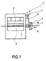
- an eccentric press 1 is schematically shown with an up and down movable carriage 2 and a lower, fixed press table 3 in an overview.
- the carriage 2 and the press table 3 carry unspecified tool halves, between which a material strip 4 is pushed intermittently when the tool halves are disengaged.
- the material strip 4 is at rest.
- the feed of this material strip 4 is effected by a feed device, generally designated 5 in FIG. 1.
- the feed device 5 is driven via a belt drive 6 by the eccentric shaft 7, which at the same time also causes the lifting movement of the carriage 2 in a known manner.
- the feed device 5 is thus driven via the same drive via which the eccentric shaft 7 is driven.
- the feed device 5 is thus synchronized with the movement of the carriage 2.
- Fig. 2 the actual feed device 5 is now shown in more detail. It can be seen that the belt drive 6 rotatably drives a cam roller 8, in which a rotary star 9 engages (cf. FIG. 3).
- a transmission gear 10 is arranged on the shaft of the rotary star 9, the transmission output shaft of which is in turn connected to a transmission input shaft 11 of a bevel gear planetary gear 12.
- the transmission output shaft 13 is connected to a feed roller 14 which, together with another roller 15, forms a conveying gap in which the material strip 4 is located and through which the material strip 4 is fed to the eccentric press 1.
- the transmission input shaft 11 and the transmission output shaft 13 of the bevel gear planetary gear 12 are arranged opposite one another coaxially and each carry a bevel gear 16 and 17, respectively.
- a gear housing 18 is rotatably arranged on the two shafts 11 and 13, which surrounds the two bevel gears 16 and 17.
- a revolving bevel gear 19 is rotatably mounted in a housing wall of the gear housing 10, the axis of rotation of which is essentially perpendicular to the two shafts 11 and 13, the bevel gear 19 meshing with both the bevel gear 16 and the bevel gear 17.
- a ring gear 20 is formed, the center of which coincides with the axis of the gear shafts 11 and 13.
- the ring gear 20 meshes with a pinion 21
- Three-phase servo motor 22 which is connected to a controller 23.
- the controller 23 controls the three-phase servo motor as a function of the respective angle of rotation of the eccentric shaft 7, for which purpose an angle encoder 24 is connected, which taps the movement of the rotary star 9 due to the synchronous transmission of the rotary movement of the eccentric shaft 7.
- the rotary movement of the eccentric shaft 7 is transmitted to the cam roller 8 via the belt drive 6.
- the rotary star 9 is rotated further by one division.
- the curve groove in the cam roller 8 is dimensioned such that the turning star 9 is at rest in good time before the punching process begins, i.e. in good time before the bottom dead center of the carriage 2, and also remains at rest until the punching process has ended and the carriage 2 has its has left bottom dead center.
- the transmission gear 10 is driven intermittently.
Landscapes
- Engineering & Computer Science (AREA)
- Mechanical Engineering (AREA)
- Perforating, Stamping-Out Or Severing By Means Other Than Cutting (AREA)
- Transmission Devices (AREA)
- Retarders (AREA)
Claims (4)
- Dispositif pour amener et faire avancer une bande de matière dans une presse à excentrique (1), comportant des rouleaux (14, 15) assurant l'avancement de la bande (4) , pouvant être entraînés en rotation par intermittence et qui sont reliés fonctionnellement par l'intermédiaire d'une ligne d'entraînement (6) avec le mécanisme d'entraînement de l'arbre à excentrique (7) de la presse, la ligne d'entraînement comportant une transmission à cames (8, 9) pour produire le mouvement de rotation intermittent des rouleaux (14, 15) en fonction de l'angle de rotation de l'arbre à excentrique (7), caractérisé en ce qu'il est prévu dans la ligne d'entraînement une transmission épicycloïdale (12), qui est reliée fonctionnellement, en vue d'une superposition d'un mouvement de rotation, additionnellement à un servo-moteur électrique (22) dont la vitesse de rotation peut être commandée en fonction de l'angle de rotation de l'arbre à excentrique (7).
- Dispositif selon la revendication 1, caractérisé en ce que la transmission épicycloïdale est agencée comme une transmission planétaire.
- Dispositif selon la revendication 2, caractérisé en ce que la transmission planétaire est agencée comme une transmission épicycloïdale à roues coniques (12), dans laquelle le porte-satellites est agencé comme un carter de transmission tournant (18), supportant la ou les roues coniques tournantes (19) et sur le côté extérieur duquel il est prévu une couronne dentée (30), en prise avec un pignon (21) du moteur (22) et servant à faire tourner le carter de transmission (18), et en ce que sur l'axe de rotation du carter de transmission sont montés à rotation des arbres d'entrée et de sortie (11, 13), reliés à la ligne de transmission et portant des roues dentées (16, 17) qui sont en prise avec la ou les roues coniques tournantes (19).
- Dispositif selon une des revendications 1 à 3, caractérisé en ce que le servomoteur est agencé comme un servomoteur à courant triphasé (22).
Applications Claiming Priority (2)
| Application Number | Priority Date | Filing Date | Title |
|---|---|---|---|
| DE3923622A DE3923622A1 (de) | 1989-07-17 | 1989-07-17 | Vorrichtung zum zufuehren und vorschieben von bandmaterial in eine exzenterpresse |
| DE3923622 | 1989-07-17 |
Publications (2)
| Publication Number | Publication Date |
|---|---|
| EP0409151A1 EP0409151A1 (fr) | 1991-01-23 |
| EP0409151B1 true EP0409151B1 (fr) | 1993-10-13 |
Family
ID=6385220
Family Applications (1)
| Application Number | Title | Priority Date | Filing Date |
|---|---|---|---|
| EP90113622A Expired - Lifetime EP0409151B1 (fr) | 1989-07-17 | 1990-07-16 | Dispositif pour alimenter et avancer du matériau en bande dans une presse excentrique |
Country Status (2)
| Country | Link |
|---|---|
| EP (1) | EP0409151B1 (fr) |
| DE (2) | DE3923622A1 (fr) |
Families Citing this family (3)
| Publication number | Priority date | Publication date | Assignee | Title |
|---|---|---|---|---|
| CH688128A5 (de) * | 1993-06-21 | 1997-05-30 | Styner & Bienz Ag | Verfahren zum Zufuehren und Vorschieben eines Streifens und Streifenanleger zur Durchfuehrung dieses Verfahrens. |
| DE10304692A1 (de) * | 2003-02-06 | 2004-08-19 | Modine Manufacturing Co., Racine | Gewellter Einsatz für ein Wärmetauscherrohr |
| CN107986056A (zh) * | 2017-12-02 | 2018-05-04 | 当涂县华胜电子元件制造厂 | 一种卷料送料装置 |
Family Cites Families (5)
| Publication number | Priority date | Publication date | Assignee | Title |
|---|---|---|---|---|
| US2201581A (en) * | 1939-01-14 | 1940-05-21 | Karl W Hallden | Flying cutting device |
| US3156150A (en) * | 1960-09-19 | 1964-11-10 | Wean Engineering Co Inc | Apparatus for acting on continuously advancing elongated material |
| US3363481A (en) * | 1964-11-24 | 1968-01-16 | Originecrs Inc | Gear drive |
| DE7128994U (de) * | 1971-07-28 | 1980-09-11 | Hinrichs Gmbh, 2054 Geesthacht | Vorrichtung fuer das stufenweise zufuehren eines materialbandes in vorbestimmbarer laenge in eine maschine |
| DE2507701A1 (de) * | 1975-02-22 | 1976-09-02 | Schuler Gmbh L | Einrichtung zum schrittweisen vorschieben von streifen- oder bandfoermigem material |
-
1989
- 1989-07-17 DE DE3923622A patent/DE3923622A1/de not_active Withdrawn
-
1990
- 1990-07-16 EP EP90113622A patent/EP0409151B1/fr not_active Expired - Lifetime
- 1990-07-16 DE DE90113622T patent/DE59003065D1/de not_active Expired - Fee Related
Also Published As
| Publication number | Publication date |
|---|---|
| EP0409151A1 (fr) | 1991-01-23 |
| DE3923622A1 (de) | 1991-01-31 |
| DE59003065D1 (de) | 1993-11-18 |
Similar Documents
| Publication | Publication Date | Title |
|---|---|---|
| DE4103160C2 (de) | Falzapparat mit einem verstellbare Elemente, insbesondere Falzklappen oder bogenförmige Segmente, aufweisenden Falzwerkzylinder | |
| DE2406076C2 (de) | Zahnradgetriebe mit Spielausgleich | |
| EP0097346A2 (fr) | Méthode et dispositif pour la fabrication des pièces munies de surfaces internes ou externes polygonales | |
| EP0443576B1 (fr) | Dispositif d'entraînement d'au moins deux axes coaxiaux dans un robot | |
| DE3539223A1 (de) | Maschine zum verarbeiten von bandmaterial | |
| DE3000321C2 (de) | Rotierende Stanzvorrichtung | |
| DE2411980C2 (de) | Schneidvorrichtung | |
| DE3608111C1 (de) | Querschneider fuer Bahnmaterialien | |
| EP0409151B1 (fr) | Dispositif pour alimenter et avancer du matériau en bande dans une presse excentrique | |
| DE3001630C2 (de) | Antriebsvorrichtung | |
| EP1099502B1 (fr) | Cisaille volante pour couper des bandes métalliques | |
| EP0403693B1 (fr) | Dispositif pour obtenir un couple pour un système de conversion de mouvement, spécialement pour l'ajustement des mors d'un mandrin ou de la force de serrage | |
| DE2034315A1 (de) | Dreh- und Vorschubeinrichtung, vorzugsweise für Kaltpilgermaschinen | |
| DE3406483A1 (de) | Vorschubeinrichtung zur schrittweisen zufuehrung von band- oder strangfoermigen werkstuecken | |
| DE1946097A1 (de) | Maschine zum Verzahnen von Kegel- oder Hypoid-Zahnraedern | |
| DE2644803A1 (de) | Bewegungsuebertragungsvorrichtung fuer ein an einem drehbaren traeger gelagertes aggregat | |
| DE878658C (de) | Vorrichtung zum Steuern der Bahngeschwindigkeit einer Verarbeitungsmaschine fuer Papier | |
| EP0059992A1 (fr) | Procédé et machine pour la fabrication de roues d'engrenages | |
| DE3637357C2 (de) | Einstellvorrichtung an einer mechanischen Presse | |
| EP0183737B1 (fr) | Installation pour la fabrication de pieces a usiner de forme exterieure et/ou interieure polygonale | |
| DE19601020C1 (de) | Werkzeugeinrichtung zur Verwendung auf Drück- und Drückwalzmaschinen | |
| DE3140333C2 (de) | Vorrichtung zur Bestückung einer taktweise betriebenen Ampullenfüll- und Verschließmaschine | |
| DD280917A5 (de) | Dreh- und vorschubeinrichtung zum absatzweisen walzen langgestreckter werkstuecke auf einem kaltpilgerwalzwerk | |
| EP1162147B1 (fr) | Dispositif pour la fabrication de sacs tubulaires ou analogues | |
| DE3311520A1 (de) | Vorschaltgetriebe zur erzeugung einer periodisch schwellenden drehbewegung der antriebswelle einer transfereinrichtung in einer presse |
Legal Events
| Date | Code | Title | Description |
|---|---|---|---|
| PUAI | Public reference made under article 153(3) epc to a published international application that has entered the european phase |
Free format text: ORIGINAL CODE: 0009012 |
|
| AK | Designated contracting states |
Kind code of ref document: A1 Designated state(s): CH DE FR IT LI |
|
| 17P | Request for examination filed |
Effective date: 19901211 |
|
| 17Q | First examination report despatched |
Effective date: 19920505 |
|
| ITF | It: translation for a ep patent filed | ||
| GRAA | (expected) grant |
Free format text: ORIGINAL CODE: 0009210 |
|
| AK | Designated contracting states |
Kind code of ref document: B1 Designated state(s): CH DE FR IT LI |
|
| REF | Corresponds to: |
Ref document number: 59003065 Country of ref document: DE Date of ref document: 19931118 |
|
| ET | Fr: translation filed | ||
| PLBE | No opposition filed within time limit |
Free format text: ORIGINAL CODE: 0009261 |
|
| STAA | Information on the status of an ep patent application or granted ep patent |
Free format text: STATUS: NO OPPOSITION FILED WITHIN TIME LIMIT |
|
| 26N | No opposition filed | ||
| PGFP | Annual fee paid to national office [announced via postgrant information from national office to epo] |
Ref country code: FR Payment date: 19960715 Year of fee payment: 7 |
|
| PGFP | Annual fee paid to national office [announced via postgrant information from national office to epo] |
Ref country code: DE Payment date: 19960830 Year of fee payment: 7 |
|
| PGFP | Annual fee paid to national office [announced via postgrant information from national office to epo] |
Ref country code: CH Payment date: 19960902 Year of fee payment: 7 |
|
| PG25 | Lapsed in a contracting state [announced via postgrant information from national office to epo] |
Ref country code: LI Free format text: LAPSE BECAUSE OF NON-PAYMENT OF DUE FEES Effective date: 19970731 Ref country code: CH Free format text: LAPSE BECAUSE OF NON-PAYMENT OF DUE FEES Effective date: 19970731 |
|
| REG | Reference to a national code |
Ref country code: CH Ref legal event code: PL |
|
| PG25 | Lapsed in a contracting state [announced via postgrant information from national office to epo] |
Ref country code: FR Free format text: LAPSE BECAUSE OF NON-PAYMENT OF DUE FEES Effective date: 19980331 |
|
| PG25 | Lapsed in a contracting state [announced via postgrant information from national office to epo] |
Ref country code: DE Free format text: LAPSE BECAUSE OF NON-PAYMENT OF DUE FEES Effective date: 19980401 |
|
| REG | Reference to a national code |
Ref country code: FR Ref legal event code: ST |
|
| PG25 | Lapsed in a contracting state [announced via postgrant information from national office to epo] |
Ref country code: IT Free format text: LAPSE BECAUSE OF NON-PAYMENT OF DUE FEES;WARNING: LAPSES OF ITALIAN PATENTS WITH EFFECTIVE DATE BEFORE 2007 MAY HAVE OCCURRED AT ANY TIME BEFORE 2007. THE CORRECT EFFECTIVE DATE MAY BE DIFFERENT FROM THE ONE RECORDED. Effective date: 20050716 |