EP0409267A1 - Vorrichtung zum automatischen Dimensionsmessen von Rotationskörper - Google Patents
Vorrichtung zum automatischen Dimensionsmessen von Rotationskörper Download PDFInfo
- Publication number
- EP0409267A1 EP0409267A1 EP90113963A EP90113963A EP0409267A1 EP 0409267 A1 EP0409267 A1 EP 0409267A1 EP 90113963 A EP90113963 A EP 90113963A EP 90113963 A EP90113963 A EP 90113963A EP 0409267 A1 EP0409267 A1 EP 0409267A1
- Authority
- EP
- European Patent Office
- Prior art keywords
- workpiece
- carriage
- axis
- feeler
- measurement
- Prior art date
- Legal status (The legal status is an assumption and is not a legal conclusion. Google has not performed a legal analysis and makes no representation as to the accuracy of the status listed.)
- Granted
Links
Images


Classifications
-
- G—PHYSICS
- G01—MEASURING; TESTING
- G01B—MEASURING LENGTH, THICKNESS OR SIMILAR LINEAR DIMENSIONS; MEASURING ANGLES; MEASURING AREAS; MEASURING IRREGULARITIES OF SURFACES OR CONTOURS
- G01B5/00—Measuring arrangements characterised by the use of mechanical techniques
- G01B5/08—Measuring arrangements characterised by the use of mechanical techniques for measuring diameters
-
- G—PHYSICS
- G01—MEASURING; TESTING
- G01B—MEASURING LENGTH, THICKNESS OR SIMILAR LINEAR DIMENSIONS; MEASURING ANGLES; MEASURING AREAS; MEASURING IRREGULARITIES OF SURFACES OR CONTOURS
- G01B7/00—Measuring arrangements characterised by the use of electric or magnetic techniques
- G01B7/28—Measuring arrangements characterised by the use of electric or magnetic techniques for measuring contours or curvatures
- G01B7/287—Measuring arrangements characterised by the use of electric or magnetic techniques for measuring contours or curvatures using a plurality of fixed, simultaneously operating transducers
Definitions
- the present invention relates to a device for the automatic measurement of the dimensions of solids of revolution, in particular for the automatic measurement of the diameters of shafts, hubs, discs and other similar mechanical workpieces; the invention also relates to a method of measurement which can be performed with this device.
- the measurement is effected by utilising a pair of feeler devices of the absolute analogue type, which are brought up to opposite parts of the workpiece to be measured, along a common rectilinear axis, measuring their displacements until the analogue measuring elements come into contact with the workpiece.
- Measuring machines of the above-mentioned type have the disadvantage that, in order to measure diameters, they require the algebraic sum of at least four measurement axes in that the measurements involve the algebraic sum of the displacements of the carriages supporting the two feelers, and the analogue measurements of these.
- at least one other analogue measurement device with associated axis of displacement is required for the measurement of shoulders orthogonal to the principal axis of the workpiece.
- the object of the invention is that of providing a measuring device which is able to take measurements of mechanical workpieces in a rapid and precise manner utilising the minimum possible number of numerical control axes, and maintaining the same general machine structure both for long workpieces and for "short" workpieces.
- a further object of the invention is that of providing a flexible, precise and economic method of measuring diameters of solids of revolution.
- the invention relates to a device for the automatic measurement of the dimensions of solids of revolution, of the type comprising first and second measurement axes along each of which a respective carriage is movable in a controlled manner, characterised by the fact that a first carriage provided with support means for a workpiece to be measured is translatable along the said first axis, and by the fact that the said second measurement axis is disposed orthogonally of a plane containing the first axis, a second carriage being translatable along the said second axis, the said second carriage carrying a projecting C-shape structure comprising a crosspiece disposed parallel to one of the said axes and a pair of arms carried on the ends of the said crosspiece and each supporting a respective feeler device projecting perpendicularly of the said crosspiece and adapted to generate a signal whenever it is brought into contact with a workpiece to be measured, the said crosspiece having a length such as to maintain between the said feelers a distance greater than the maximum
- the invention further relates to an automatic method of measuring the dimensions of solids of revolution, in particular for measuring diameters, characterised by the fact that it comprises the following stages: - mounting a workpiece to be measured in a predetermined position on a first carriage; - arranging a pair of feeler devices, each of which can generate a signal when it contacts the said workpiece to be measured, at a predetermined distance from one another greater than the maximum value to be measured, the said feeler devices being disposed parallel to one another and lying in the same plane; - relatively displacing the workpiece to be measured with respect to the feeler devices while maintaining these fixed with respect to one another, the said displacement being parallel to the said plane in which the feelers lie and in such a way as to intersect the workpiece in a longitudinal median plane thereof, with a first, and then reversing the sense of the relative displacement, with a second of the said feelers; - calculating the size of the workpiece by subtracting from the value of the said predetermined distance between the feelers the absolute value of the relative displacement
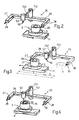
- the reference numeral 1 indicates a device for effecting automatic measurement of the dimensions, in particular the diameters, of a mechanical workpiece 2, for example having two cylindrical abutments 3, 4 of different diameters and, more generally, of any solid of revolution; in the illustrated example the device 1 is served by an automatic loading station 6 having a zone 8 for stacking workpieces to be measured, a loading zone 7 and a robot manipulator 9 of known type acting to transfer the workpieces 2 from the storage zone 8 to the loading zone 7.
- This latter is an integral part of the device 1, which has a first measurement axis 10 of the numerical control type on which the first carriage 11 is mounted in a controllably translatable manner and a second measurement axis 12, also of numerically controlled type, on which a second carriage 14 is mounted also in a controllably translatable manner;
- the numerical control axes 10 and 12 are, in the illustrated embodiment defined by respective rectilinear guides provided with suitable motor means for the carriages 11, 14 and detector means for detecting the position thereof with respect to a system of reference coordinates, all known and not illustrated for simplicity.
- the carriages 11, 14 can be motorised by suitable servo-motors provided with encoders connected to an electronic central control unit 16.
- the axis 12 is disposed perpendicularly to the plane in which the axis 10 is contained; in the illustrated example the axis 10 and the associated carriage 11 are supported horizontally by a bed 18, whilst the axis 12 and the associated carriage 14 are supported by a vertical column 19 disposed to one side of the bed 18.
- the axis 10 has a length such as to define the loading zone 7 with its terminal end 20, when this is occupied by the carriage 11; therefore, in substance, the axis 10 is dimensioned in such a way as to be able to transfer the carriage 11 between the loading zone 7 and a measurement zone 21 disposed in correspondence with the column 19 so that the axis 10, as well as being the measurement axis, also functions as a workpiece transfer axis; the carriage 11, thanks to its position, is in fact adapted to receive and support the workpieces 2 to be measured, which are loaded and unloaded from it one at a time by the manipulator 9 when the carriage 11 is at its end of stroke position at the end 20 of the axis 10; for the purpose of supporting the workpieces 2 in a precise and fixed position the carriage 11 is further provided with support means which, in the case of short round workpieces, such as the workpiece 2 illustrated, consists of a workpiece carrier table 22 of the type provided with self-centring jaws (not illustrated) and preferably mounted for rotation on the
- the second carriage 14 is on the other hand provided with a sensor system adapted to permit it to effect the desired measurement and which, in the illustrated example, is a contact system which is insensitive to the presence of possible oil or water films on the workpiece to be measured.
- the carriage 14 carries a forwardly projecting C-shape structure 25 lying in a plane parallel to that of the two numerical control axes 10, 12, which is utilised to effect measurement, in the illustrated example, in the case of short round workpieces, parallel to the axis 10 and, in particular, to the said plane containing the axis 10;
- the C-shape structure 25 is positioned with its open part facing away from the axis 12 and comprises a crosspiece 26 disposed parallel to the axis 10 and extending transversely of the axis 12, and a pair of arms 27, 28 formed on the opposite ends of the crosspiece 26 and each supporting a respective feeler device of known type, respectively 29 and 30, adapted to generate a signal for the central control unit 16 whenever it is carried into contact with the
- the sequence of operations is as follows.
- the workpiece 2 to be measured is mounted on the carriage 11, on which the workpiece 2 is then retained in a predetermined position by the table 22, by displacing the carriage 11 along the axis 10 into the loading zone 7 and operating the manipulator 9 in a suitable manner; then the carriage 11 with the workpiece 2 is carried into the measurement zone 21 by means of a displacement in an opposite sense along the axis 10.
- the structure 25 is lowered along the column 19 in such a way as to bring it too into the measurement zone 21 as soon as the workpiece 2 has passed the position occupied by the feeler 29, that is as soon as the carriage 11 is located, in a horizontal sense, in correspondence with the crosspiece 10, between the arms 27 and 28; this pre-arrangement of the structure 25 is obtained by a displacement of the carriage 14 along the axis 12 until the feelers 29, 30 are brought, in a vertical sense, into correspondence with the cylindrical surface of the workpiece 2 the diameter of which it is desired to measure, for example the surface 3 the position of which is known in that the theoretical coordinates of the workpiece 2, referred to the position of the table 22 have been preliminarily memorised in the central control unit 16 by which the servo motors of the axes 10 and 12 are controlled.
- the measurement is initiated, which is performed by effecting a movement of the carriage 11 along the axis 10 and holding the structure 25 stationary on the axis 12: the carriage 11 is displaced in a predetermined direction, for example that illustrated by the arrow in Figure 2, and parallel to the common plane in which the feelers 29, 30 and the crosspiece 26 lie, in such a way as to intercept the workpiece 2, in the illustrated example the cylindrical surface 3 thereof, by the feeler 30.
- the value of the distance L reduced by the value of the two dynamic radii of the feelers 29, 30 (which is now memorised in the central control unit 16 as a constant of the device 1) is obtained by measurement with the feelers 29, 30 of a workpiece of known, rigorously exact dimensions, introduced manually or automatically between the palpators 29, 30 "una tantum" when necessary.
- the device 1 can also include a further feeler device 50 of known type (preferably of the zero switch type, but could also be of the absolute analogue type), which is also able to send a signal to the central control unit 16 whenever it is brought into contact with a workpiece 2 to be measured, similarly to the feelers 29, 30, and which is carried fixedly by the structure 25 perpendicularly to the feelers 29, 30, in the illustrated example by a linear actuator 52 carried fixedly on the crosspiece 26 by means of an arm 152 supported by a small column 153 in such a way as to position the feeler 50 in co-planar alignment with the ends of the feelers 29, 30 intended to come into contact with the workpiece to be measured; this actuator 52 is adapted to displace the feeler selectively, in a vertical direction between two end-of-stroke positions, in particular between a rest position, illustrated in Figures 1, 2 and 3, in which the feeler 50 is retracted towards the crosspiece 26, in which position it cannot interfere with the workpiece 2 to be measured while this is displaced between the feelers 29, 30,
- the feeler 50 is brought into working position by operation of the actuator 52 in such a way as to bring it, for example, into the interior of the hole 70 as soon as the workpiece 2 reaches the position under the feeler itself; then the carriage 11 is actuated to bring the feeler 50 into contact with the internal wall of the hole 70, the feeler being positioned in correspondence with the median plane of the workpiece 2; as soon as the feeler 50 touches the workpiece 2 a signal is sent to the central control unit 16 which reverses the movement of the carriage 11 and starts to memorise the displacement until the feeler 50 again contacts the internal wall of the hole 70 (from the opposite side this time) sending a new signal to the central control unit 16 which, on the basis of the displacement performed by the carriage 11 between the reception of the two feeler signals 50 calculates the diameter of the hole 70, taking into account the dynamic diameter of the feeler itself, just on the basis of this displacement.
- the feeler 50 can be brought into the measurement position in the same "on/off" way previously described, or rather only when required, even without necessarily having an actuator able to move it vertically; for example, the feeler 50, in a possible variant not illustrated for simplicity, could be located at a fixed position at a suitable vertical height on the arm 152 and this could be made rotatable about the column 153; in this case the actuator 52 would consist of an apparatus adapted to control the arm 152 to rotate between the position illustrated, in which it is perpendicular to the crosspiece 26, and a rest position in which the arm 152 is located back against the crosspiece 26, substantially parallel thereto, so as to avoid interference between the workpiece to be measured and the feeler 50 whilst the feelers 29 and 30 are in use.
- the supplementary feeler 50 is normally absent and in its place one of the two feelers 29, 30 is utilised for the measurement of internal diameters by positioning these in a suitable manner by means of a constructional arrangement.
- the crosspiece 26 is not directly mounted fixedly to the carriage 14 in a fixed position, but is fixed in correspondence with its middle, projecting transversely from an arm 80, which is disposed orthogonally of the plane containing the crosspiece 26 and the feelers 29, 30 (that is the plane in which the structure 25 lies); the arm 80 is in turn carried fixedly projecting radially from a motorised platform 82, which is rotatably carried about an axis 83 by a turret 84 projecting forwardly from the carriage 14.
- the platform 82 is mounted on the turret 84 in such a way that the axis 83 is disposed obliquely with respect to the numerical control axis 12 and, in particular, in such a way that it forms an angle of 45° with this latter. Therefore, from the normal working position of figures from 1 to 5, the structure 25 provided with the feelers 29, 30 can be made to rotate through 180° about the oblique axis 83 ( Figure 6) by actuating the motorised platform 82 until it brings it into the inverted position illustrated in Figure 7. In this position the feelers 29, 30 are substantially vertical and parallel to the second numerical control axis 14, or rather are rotated through 90° on a vertical plane with respect to the position of Figure 5. Consequently it is possible to utilised one (or both) of the feelers 29, 30 as previously described in respect of the feeler 50, in such a way as to detect also internal diameters of the workpiece under test.
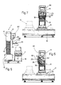
- the workpiece to be measured is of elongate form, such as a shaft 102 for example provided with a flange 103 having holes 104
- a device 1A entirely similar to the device 1 already described and in substance derivable from the device 1 with minimum modifications solely at the equipment level; the similar or identical details to those already described are indicated for simplicity with the same reference numerals.
- the device 1A is formed by the same principle components as the device 1: the two numerical control axes 10, 12 and associated carriages 11, 14 and associated support structures 18, 19, the central control unit 16, the C-shape structure 25 with the associated projecting feelers 29, 30 supported by a predetermined distance L from one another by the crosspiece 26; the single difference consists in the fact that the turret 84 is mounted on the carriage 14 rotated through 90° with respect to the position in which it is assembled on the device 1, and by the fact that the carriage 11, rather than being equipped with the workpiece carrier table 22, is provided with support means of a type adapted to the workpiece 102 to be measured; in the illustrated example the carriage 11 is provided with a pair of opposite brackets 24 provided with spikes or other clamping devices, for example of the self-centring type used on lathes, which support the workpiece 102 at its opposite ends in such a way that this is disposed with its longitudinal median plane in correspondence with the ends of the feelers 29, 30; at least one of the brackets 24 is further provided with a
- the measurement of the diameter of the different engagements surfaces is effected by bringing the carriages 11 and 14 into the measurement zone, disposing them in such a way that the cylindrical surface the diameter of which it is desired to measure is located in correspondence with the second numerical control axis 14 facing the crosspiece 26 and disposed between the feelers 29, 30, which are supported horizontally and perpendicular to the axis 10, the crosspiece 26 being supported by the carriage 14 in such a way as to be constantly parallel to the axis 12; then, by holding the carriage 11 stationary a measurement stroke is effected with the carriage 14; the structure 25 is, for example, lowered towards the carriage 11 and, as soon as the upper feeler 29 interferes with the surface the diameter of which it is desired to measure, for example the surface 102, a signal is sent to the central control unit 16, which reverses the motion of the carriage 14 and commences to memorise the displacement which it performs in
- the same feelers 29, 30 can be utilised as are used for the measurement of external diameters, one at a time, having turned these through 90° effected by making the platform 82 turn through 180° about the axis 83 which, in this case too, given the form of the turret 84, is disposed obliquely and forming an angle of 45° with the first numerical control axis 10; by operating in the manner described, the C-shape structure 25 is turned over in such a way as to carry it from the position of Figure 8 to that of Figure 9; in this position it is possible, by means of displacement of the carriage 11, to carry one of the feelers 29, 30, for example the feeler 29, into the hole 104 the diameter of which it is desired to measure and, then, to effect measurement by displacing the carriage 14 first in one direction, for example upward and then, after the feeler 29 has come into contact against the inner wall of the hole 104, in the opposite direction until it
Landscapes
- Physics & Mathematics (AREA)
- General Physics & Mathematics (AREA)
- A Measuring Device Byusing Mechanical Method (AREA)
- Machine Tool Sensing Apparatuses (AREA)
- Length Measuring Devices With Unspecified Measuring Means (AREA)
Applications Claiming Priority (2)
| Application Number | Priority Date | Filing Date | Title |
|---|---|---|---|
| IT8967616A IT1232879B (it) | 1989-07-21 | 1989-07-21 | Dispositivo e metodo per la misurazione automatica delle dimensioni di solidi di rivoluzione |
| IT6761689 | 1989-07-21 |
Publications (2)
| Publication Number | Publication Date |
|---|---|
| EP0409267A1 true EP0409267A1 (de) | 1991-01-23 |
| EP0409267B1 EP0409267B1 (de) | 1993-06-02 |
Family
ID=11303908
Family Applications (1)
| Application Number | Title | Priority Date | Filing Date |
|---|---|---|---|
| EP90113963A Expired - Lifetime EP0409267B1 (de) | 1989-07-21 | 1990-07-20 | Vorrichtung zum automatischen Dimensionsmessen von Rotationskörper |
Country Status (3)
| Country | Link |
|---|---|
| EP (1) | EP0409267B1 (de) |
| DE (1) | DE69001787T2 (de) |
| IT (1) | IT1232879B (de) |
Cited By (7)
| Publication number | Priority date | Publication date | Assignee | Title |
|---|---|---|---|---|
| WO1991019162A1 (en) * | 1990-05-30 | 1991-12-12 | Marposs Società per Azioni | Method and apparatus for dynamically checking dimensions of mechanical parts |
| EP0802393A3 (de) * | 1996-04-15 | 1998-04-15 | Carl Zeiss | Messeinrichtung zur Vermessung von Werkstücken |
| EP1548395A3 (de) * | 2003-12-22 | 2006-12-13 | Mitutoyo Corporation | Messgerät für Oberflächentextur und Breitenmessverfahren |
| CN101975925A (zh) * | 2010-10-12 | 2011-02-16 | 浙江深度光电科技有限公司 | 一种发电机总装测试系统 |
| JP6031732B1 (ja) * | 2015-08-27 | 2016-11-24 | 株式会社東京精密 | 表面形状測定装置の心ずれ量算出方法、及び表面形状測定装置 |
| CN108955461A (zh) * | 2018-08-17 | 2018-12-07 | 海安金锻工业有限公司 | 一种检测设备及检测方法 |
| CN112729154A (zh) * | 2020-12-22 | 2021-04-30 | 重庆富吉机械制造有限公司 | 一种轮毂毛坯外缘变形量的检测装置 |
Citations (7)
| Publication number | Priority date | Publication date | Assignee | Title |
|---|---|---|---|---|
| EP0157176A2 (de) * | 1984-04-04 | 1985-10-09 | Marposs Societa' Per Azioni | Vorrichtung zur Dimensionsmessung, insbesondere Diametral- und Axialdimensionen von Teilen mit Rotationssymmetrie |
| US4562392A (en) * | 1984-08-29 | 1985-12-31 | General Electric Company | Stylus type touch probe system |
| EP0199927A1 (de) * | 1985-04-01 | 1986-11-05 | Marposs Societa' Per Azioni | Vorrichtung zum Bestimmen linearer Abmessungen mechanischer Teile |
| EP0240151A2 (de) * | 1986-03-04 | 1987-10-07 | Rank Taylor Hobson Limited | Metrologischer Apparat |
| GB2203837A (en) * | 1987-04-06 | 1988-10-26 | Mitutoyo Corp | Apparatus and method for spatial coordinate measurement |
| DE3713247A1 (de) * | 1987-04-18 | 1988-10-27 | Schaudt Maschinenbau Gmbh | Messkopf, insbesondere fuer schleifmaschinen |
| EP0315575A1 (de) * | 1987-09-18 | 1989-05-10 | H. Wohlenberg KG GmbH & Co. | Verfahren und Messvorrichtung zur Durchmesserermittlung von Walzen |
-
1989
- 1989-07-21 IT IT8967616A patent/IT1232879B/it active
-
1990
- 1990-07-20 EP EP90113963A patent/EP0409267B1/de not_active Expired - Lifetime
- 1990-07-20 DE DE90113963T patent/DE69001787T2/de not_active Expired - Fee Related
Patent Citations (7)
| Publication number | Priority date | Publication date | Assignee | Title |
|---|---|---|---|---|
| EP0157176A2 (de) * | 1984-04-04 | 1985-10-09 | Marposs Societa' Per Azioni | Vorrichtung zur Dimensionsmessung, insbesondere Diametral- und Axialdimensionen von Teilen mit Rotationssymmetrie |
| US4562392A (en) * | 1984-08-29 | 1985-12-31 | General Electric Company | Stylus type touch probe system |
| EP0199927A1 (de) * | 1985-04-01 | 1986-11-05 | Marposs Societa' Per Azioni | Vorrichtung zum Bestimmen linearer Abmessungen mechanischer Teile |
| EP0240151A2 (de) * | 1986-03-04 | 1987-10-07 | Rank Taylor Hobson Limited | Metrologischer Apparat |
| GB2203837A (en) * | 1987-04-06 | 1988-10-26 | Mitutoyo Corp | Apparatus and method for spatial coordinate measurement |
| DE3713247A1 (de) * | 1987-04-18 | 1988-10-27 | Schaudt Maschinenbau Gmbh | Messkopf, insbesondere fuer schleifmaschinen |
| EP0315575A1 (de) * | 1987-09-18 | 1989-05-10 | H. Wohlenberg KG GmbH & Co. | Verfahren und Messvorrichtung zur Durchmesserermittlung von Walzen |
Cited By (13)
| Publication number | Priority date | Publication date | Assignee | Title |
|---|---|---|---|---|
| WO1991019162A1 (en) * | 1990-05-30 | 1991-12-12 | Marposs Società per Azioni | Method and apparatus for dynamically checking dimensions of mechanical parts |
| US5205047A (en) * | 1990-05-30 | 1993-04-27 | Marposs Societa' Per Azioni | Method and apparatus for dynamically checking dimensions of mechanical parts |
| EP0802393A3 (de) * | 1996-04-15 | 1998-04-15 | Carl Zeiss | Messeinrichtung zur Vermessung von Werkstücken |
| US5901455A (en) * | 1996-04-15 | 1999-05-11 | Carl-Zeiss-Stiftung Trading As Carl Zeiss | Measuring device for measuring workpieces |
| USRE37695E1 (en) * | 1996-04-15 | 2002-05-14 | Carl-Zeiss-Stiftung | Measuring device for measuring workpieces |
| EP1548395A3 (de) * | 2003-12-22 | 2006-12-13 | Mitutoyo Corporation | Messgerät für Oberflächentextur und Breitenmessverfahren |
| CN101975925A (zh) * | 2010-10-12 | 2011-02-16 | 浙江深度光电科技有限公司 | 一种发电机总装测试系统 |
| CN101975925B (zh) * | 2010-10-12 | 2013-03-20 | 浙江深度光电科技有限公司 | 一种发电机总装测试系统 |
| JP6031732B1 (ja) * | 2015-08-27 | 2016-11-24 | 株式会社東京精密 | 表面形状測定装置の心ずれ量算出方法、及び表面形状測定装置 |
| US10041779B2 (en) | 2015-08-27 | 2018-08-07 | Tokyo Seimitsu Co., Ltd. | Surface shape measuring method, misalignment amount calculating method, and surface shape measuring device |
| CN108955461A (zh) * | 2018-08-17 | 2018-12-07 | 海安金锻工业有限公司 | 一种检测设备及检测方法 |
| CN108955461B (zh) * | 2018-08-17 | 2023-12-22 | 海安金锻工业有限公司 | 一种检测设备及检测方法 |
| CN112729154A (zh) * | 2020-12-22 | 2021-04-30 | 重庆富吉机械制造有限公司 | 一种轮毂毛坯外缘变形量的检测装置 |
Also Published As
| Publication number | Publication date |
|---|---|
| IT8967616A0 (it) | 1989-07-21 |
| DE69001787D1 (de) | 1993-07-08 |
| DE69001787T2 (de) | 1993-10-07 |
| EP0409267B1 (de) | 1993-06-02 |
| IT1232879B (it) | 1992-03-05 |
Similar Documents
| Publication | Publication Date | Title |
|---|---|---|
| US5323572A (en) | Precision grinding machine | |
| US4484293A (en) | Dimensional measurement system served by a plurality of operating arms and controlled by a computer system | |
| JPH07109361B2 (ja) | 割出し機構 | |
| SU1025340A3 (ru) | Способ контрол профил зубьев зубчатого колеса и устройство дл его осуществлени | |
| US4807400A (en) | Measuring apparatus for grinding machines for cylinders with structural and surface checking devices | |
| CN101357443A (zh) | 具有通过接触检测来校正安装误差的功能的机床 | |
| EP0157176B1 (de) | Vorrichtung zur Dimensionsmessung, insbesondere Diametral- und Axialdimensionen von Teilen mit Rotationssymmetrie | |
| EP0390204A2 (de) | Drehtisch für einen Koordinaten-Messapparat und Verfahren zum Feststellen der Drehachse vom Tisch | |
| EP0409267B1 (de) | Vorrichtung zum automatischen Dimensionsmessen von Rotationskörper | |
| CN105890539A (zh) | 一种回转体零件加工精度快速自动测量装置以及方法 | |
| JP2831610B2 (ja) | 測定装置 | |
| KR20010040092A (ko) | 개선된 자동차 차체 자동 조립 및 용접 스테이션 | |
| US20090112508A1 (en) | Measuring apparatus for heavy workpieces and workpiece receiver for such a measuring apparatus | |
| US4680865A (en) | Apparatus for checking linear dimensions | |
| GB2045935A (en) | Apparatus for checking the linear dimensions of shafts | |
| EP0410321A2 (de) | Verfahren und Vorrichtung zum automatischen Diameter- und Längemessen von Rotationskörpern | |
| JP3701449B2 (ja) | ロール計測方法およびその装置 | |
| CN114303109B (zh) | 数控机床的操作方法以及用于实施这样的方法的检测装置 | |
| US20210190468A1 (en) | Measuring method and measuring system for measuring drilled holes, and precision machine tool with a measuring system | |
| JPH11142138A (ja) | 3次元自動計測装置 | |
| US5461920A (en) | Whole-body test system with a test probe mount designed especially as a rotor which is mounted on a vertically adjustable support platform and has a test-piece manipulator | |
| EP0672885A2 (de) | Koördinatenmessmaschine | |
| GB2103129A (en) | Arrangement in a coordinate grinding machine of a measuring apparatus for determining the position of a workpiece surface which is being ground | |
| EP0335474A2 (de) | Metrologische Vorrichtung | |
| CN211717408U (zh) | 轴承外圈沟道检测设备 |
Legal Events
| Date | Code | Title | Description |
|---|---|---|---|
| PUAI | Public reference made under article 153(3) epc to a published international application that has entered the european phase |
Free format text: ORIGINAL CODE: 0009012 |
|
| AK | Designated contracting states |
Kind code of ref document: A1 Designated state(s): BE CH DE ES FR GB IT LI NL SE |
|
| 17P | Request for examination filed |
Effective date: 19910529 |
|
| 17Q | First examination report despatched |
Effective date: 19920128 |
|
| GRAA | (expected) grant |
Free format text: ORIGINAL CODE: 0009210 |
|
| AK | Designated contracting states |
Kind code of ref document: B1 Designated state(s): BE CH DE ES FR GB IT LI NL SE |
|
| PG25 | Lapsed in a contracting state [announced via postgrant information from national office to epo] |
Ref country code: NL Effective date: 19930602 Ref country code: LI Effective date: 19930602 Ref country code: ES Free format text: THE PATENT HAS BEEN ANNULLED BY A DECISION OF A NATIONAL AUTHORITY Effective date: 19930602 Ref country code: CH Effective date: 19930602 Ref country code: BE Effective date: 19930602 |
|
| ITF | It: translation for a ep patent filed | ||
| REF | Corresponds to: |
Ref document number: 69001787 Country of ref document: DE Date of ref document: 19930708 |
|
| PGFP | Annual fee paid to national office [announced via postgrant information from national office to epo] |
Ref country code: FR Payment date: 19930720 Year of fee payment: 4 |
|
| PGFP | Annual fee paid to national office [announced via postgrant information from national office to epo] |
Ref country code: SE Payment date: 19930728 Year of fee payment: 4 |
|
| ET | Fr: translation filed | ||
| PGFP | Annual fee paid to national office [announced via postgrant information from national office to epo] |
Ref country code: DE Payment date: 19930730 Year of fee payment: 4 |
|
| REG | Reference to a national code |
Ref country code: CH Ref legal event code: PL |
|
| NLV1 | Nl: lapsed or annulled due to failure to fulfill the requirements of art. 29p and 29m of the patents act | ||
| PLBE | No opposition filed within time limit |
Free format text: ORIGINAL CODE: 0009261 |
|
| 26N | No opposition filed | ||
| PG25 | Lapsed in a contracting state [announced via postgrant information from national office to epo] |
Ref country code: GB Effective date: 19940720 |
|
| PG25 | Lapsed in a contracting state [announced via postgrant information from national office to epo] |
Ref country code: SE Effective date: 19940721 |
|
| EUG | Se: european patent has lapsed |
Ref document number: 90113963.4 Effective date: 19950210 |
|
| GBPC | Gb: european patent ceased through non-payment of renewal fee |
Effective date: 19940720 |
|
| PG25 | Lapsed in a contracting state [announced via postgrant information from national office to epo] |
Ref country code: FR Effective date: 19950331 |
|
| PG25 | Lapsed in a contracting state [announced via postgrant information from national office to epo] |
Ref country code: DE Effective date: 19950401 |
|
| EUG | Se: european patent has lapsed |
Ref document number: 90113963.4 |
|
| REG | Reference to a national code |
Ref country code: FR Ref legal event code: ST |
|
| PG25 | Lapsed in a contracting state [announced via postgrant information from national office to epo] |
Ref country code: IT Free format text: LAPSE BECAUSE OF NON-PAYMENT OF DUE FEES Effective date: 20050720 |