EP0409309A1 - Vorlagen-Handhabungseinrichtung vom Umlauftyp - Google Patents
Vorlagen-Handhabungseinrichtung vom Umlauftyp Download PDFInfo
- Publication number
- EP0409309A1 EP0409309A1 EP90201826A EP90201826A EP0409309A1 EP 0409309 A1 EP0409309 A1 EP 0409309A1 EP 90201826 A EP90201826 A EP 90201826A EP 90201826 A EP90201826 A EP 90201826A EP 0409309 A1 EP0409309 A1 EP 0409309A1
- Authority
- EP
- European Patent Office
- Prior art keywords
- path
- discharge
- original
- conveyor
- discharge path
- Prior art date
- Legal status (The legal status is an assumption and is not a legal conclusion. Google has not performed a legal analysis and makes no representation as to the accuracy of the status listed.)
- Granted
Links
- 230000003134 recirculating effect Effects 0.000 title claims description 4
- 230000002441 reversible effect Effects 0.000 claims abstract description 8
- 230000033001 locomotion Effects 0.000 claims description 4
- 230000001154 acute effect Effects 0.000 claims description 2
- 238000007599 discharging Methods 0.000 claims description 2
- 238000012545 processing Methods 0.000 description 5
- 238000010276 construction Methods 0.000 description 2
- 238000000034 method Methods 0.000 description 2
Images
Classifications
-
- G—PHYSICS
- G03—PHOTOGRAPHY; CINEMATOGRAPHY; ANALOGOUS TECHNIQUES USING WAVES OTHER THAN OPTICAL WAVES; ELECTROGRAPHY; HOLOGRAPHY
- G03G—ELECTROGRAPHY; ELECTROPHOTOGRAPHY; MAGNETOGRAPHY
- G03G15/00—Apparatus for electrographic processes using a charge pattern
- G03G15/60—Apparatus which relate to the handling of originals
-
- G—PHYSICS
- G03—PHOTOGRAPHY; CINEMATOGRAPHY; ANALOGOUS TECHNIQUES USING WAVES OTHER THAN OPTICAL WAVES; ELECTROGRAPHY; HOLOGRAPHY
- G03B—APPARATUS OR ARRANGEMENTS FOR TAKING PHOTOGRAPHS OR FOR PROJECTING OR VIEWING THEM; APPARATUS OR ARRANGEMENTS EMPLOYING ANALOGOUS TECHNIQUES USING WAVES OTHER THAN OPTICAL WAVES; ACCESSORIES THEREFOR
- G03B27/00—Photographic printing apparatus
- G03B27/32—Projection printing apparatus, e.g. enlarger, copying camera
- G03B27/52—Details
- G03B27/62—Holders for the original
- G03B27/6207—Holders for the original in copying cameras
- G03B27/625—Apparatus which relate to the handling of originals, e.g. presence detectors, inverters
- G03B27/6257—Arrangements for moving an original once or repeatedly to or through an exposure station
-
- G—PHYSICS
- G03—PHOTOGRAPHY; CINEMATOGRAPHY; ANALOGOUS TECHNIQUES USING WAVES OTHER THAN OPTICAL WAVES; ELECTROGRAPHY; HOLOGRAPHY
- G03G—ELECTROGRAPHY; ELECTROPHOTOGRAPHY; MAGNETOGRAPHY
- G03G15/00—Apparatus for electrographic processes using a charge pattern
- G03G15/22—Apparatus for electrographic processes using a charge pattern involving the combination of more than one step according to groups G03G13/02 - G03G13/20
- G03G15/23—Apparatus for electrographic processes using a charge pattern involving the combination of more than one step according to groups G03G13/02 - G03G13/20 specially adapted for copying both sides of an original or for copying on both sides of a recording or image-receiving material
-
- G—PHYSICS
- G03—PHOTOGRAPHY; CINEMATOGRAPHY; ANALOGOUS TECHNIQUES USING WAVES OTHER THAN OPTICAL WAVES; ELECTROGRAPHY; HOLOGRAPHY
- G03G—ELECTROGRAPHY; ELECTROPHOTOGRAPHY; MAGNETOGRAPHY
- G03G2215/00—Apparatus for electrophotographic processes
- G03G2215/00172—Apparatus for electrophotographic processes relative to the original handling
- G03G2215/00177—Apparatus for electrophotographic processes relative to the original handling for scanning
- G03G2215/00181—Apparatus for electrophotographic processes relative to the original handling for scanning concerning the original's state of motion
- G03G2215/00185—Apparatus for electrophotographic processes relative to the original handling for scanning concerning the original's state of motion original at rest
-
- Y—GENERAL TAGGING OF NEW TECHNOLOGICAL DEVELOPMENTS; GENERAL TAGGING OF CROSS-SECTIONAL TECHNOLOGIES SPANNING OVER SEVERAL SECTIONS OF THE IPC; TECHNICAL SUBJECTS COVERED BY FORMER USPC CROSS-REFERENCE ART COLLECTIONS [XRACs] AND DIGESTS
- Y10—TECHNICAL SUBJECTS COVERED BY FORMER USPC
- Y10S—TECHNICAL SUBJECTS COVERED BY FORMER USPC CROSS-REFERENCE ART COLLECTIONS [XRACs] AND DIGESTS
- Y10S271/00—Sheet feeding or delivering
- Y10S271/902—Reverse direction of sheet movement
Definitions
- This invention relates to apparatus for recirculating originals from a stack thereof to an exposure zone of a copying machine and back from the exposure zone to the stack of originals, comprising a cassette for the stack of originals, a feed path extending from the bottom of the cassette to a first side of the exposure zone for feeding an original from the cassette to the exposure zone, conveying means for conveying the original in a first conveyor path through the exposure zone, a discharge path extending from a second side of the exposure zone to the top of the cassette for discharging the original from the exposure zone to the cassette, with reversal of the original, a second conveyor path extending from the exposure zone to the discharge path and a sheet conveyor member in the discharge path, the direction of conveyance of which is reversible for reversing the direction of movement of the original.
- An apparatus of this kind is known from European Patent 0 078 680, which describes an apparatus in which the sheet conveyor member is disposed on the second side of an exposure platen forming the exposure zone, such second side being remote from the feed path, the second conveyor path extending from the said second side in the direction of the cassette to discharge the original to the cassette without reversal of the original, a return path, for directly returning an original from and to the exposure platen - with reversal of the original - extending from said second side to the first side of the exposure platen situated opposite said second side, the said return path and second conveyor path extending between the first conveyor path over the exposure platen and the discharge path.
- an original must be capable of moving at three levels above the exposure platen namely: - through the first conveyor path directly over the exposure platen, - through that portion of the discharge path which is situated thereabove and - through that portion of the second conveyor path and of the return path which is situated between the first conveyor path over the exposure platen and the discharge path.
- the first conveyor path over the exposure platen and the two paths thereabove must each be separately accessible, and this necessitates a complex construction.
- the object of this invention is to provide an apparatus of the type referred to in the preamble without this disadvantage.
- this object is attained in that in an apparatus according to the preamble the second conveyor path extends from the first side of the exposure zone to the discharge path for conveying the original without reversal and in that the sheet conveyor member in the discharge path is disposed past the location where the second conveyor path leads into the discharge path. Consequently, there is only one path above the first conveyor path through the exposure zone, so that these paths can readily be made accessible.
- an original returning to the cassette through the discharge path until just before it reaches the cassette can still be returned directly to the exposure zone by reversing the direction of the conveyance of the sheet conveyor member disposed near the cassette.
- the direction of conveyance of the conveyor means for conveying the original in the first conveyor path is reversible. Consequently, the total path length required is short, thus reducing the risk of originals jamming. This is particularly the case in an apparatus in which the exposure zone is adapted to position the entire original therein. Also, an original can be discharged directly from the exposure zone via the second conveyor path to the cassette without reversal of the original and, by reversing the direction of conveyance of the sheet conveyor member, can be directly returned to the exposure zone until just before it reaches the cassette.
- the known apparatus shown in Fig. 1 comprises an exposure zone 1 in which is disposed an exposure platen 2 of a copying machine not shown in greater detail. Disposed next to the exposure platen 2 is a cassette 3 in which a stack 4 of originals to be copied can be placed.
- a feed path 5 extends from the bottom of the cassette 3 to the feed side 6 of the exposure platen 2, which side is situated closest to the cassette 3, for feeding an original to the exposure platen 2 without reversal, such original being separated form the bottom of the stack 4.
- a conveyor belt 7 cooperates with the exposure platen 2 in order to transport an original over said platen from the feed side 6 to the discharge side 8 of the exposure platen 2 situated opposite said feed side.
- a first discharge path 10 extends from the discharge side 8 of the exposure platen 2 to the top of the cassette 3.
- This first discharge path 10 comprises a semi-circularly curved portion which adjoins the discharge side 8 and a straight portion which extends from the curved portion to the cassette 3.
- a second discharge path 11 also extends like the first discharge path 10 from the discharge side 8 of the exposure platen 2 to the cassette 3.
- This second discharge path 11 contains that portion of the discharge path 10 which adjoins the discharge side 8 of the exposure platen 2, a portion which extends between said discharge side 8 and a location 12 in the first discharge path 10 which is situated approximately straight above the feed side 6 of the exposure platen 2, which portion is situated between the exposure platen 2 and the straight portion of the first conveyor path 10.
- the known apparatus also comprises a return path 13 extending from the discharge side 8 of the exposure platen 2 to the feed side 6 of exposure platen 2, which return path 13 is formed by that portion of the first discharge path 10 which adjoins the discharge side 8, that portion of the second discharge path 11 which extends between the discharge side 8 and location 12 of the first discharge path 10 and a semi-circularly curved portion which extends between location 12 and feed side 6 of the exposure platen.
- a sheet conveyor roller 15 is disposed at the curved portion of the first discharge path 10 and its direction of conveyance is reversible.
- a sheet deflector 16 is disposed at the discharge side 8 and can be set into a position in which an original fed in the direction of the exposure platen 2 by the sheet conveyor roller 15 is guided in the direction of location 12, and a sheet deflector 17 is disposed at location 12 and can be set into a position in which an original is returned to the exposure platen 2.
- Originals printed on one side are fed one by one from stack 4 to the exposure platen 2 and from there back to the stack 4 via the second discharge path 11.
- Originals printed on both sides can be processed in two ways:
- Method a is suitable for use in a copying machine in which copy sheets printed on one side are collected in an intermediate stack before printing the other side
- method b. is suitable for use in a copying machine in which all copy sheets are printed on both sides directly after one another.
- the known apparatus shown in Fig. 1 has a number of disadvantages.
- One such disadvantage is that portion of the second discharge path 11 and of the return path 13 respectively which extends between the discharge side 8 and the location 12 where said discharge path 11 and return path 13 respectively lead into the first discharge path 10 is difficultly accessible, for example, for removal of an original jammed in such portion.
- the conveyor system above the exposure platen 2 must, for example, be adapted to hinge up in portions for the purpose.
- Another disadvantage is that three conveyor paths extend one above the other over the entire length of and above the exposure platen 2, and apart from a complex conveyor construction this means considerable risk of an original jamming in one of these long conveyor paths.
- a feed path 21 between a cassette 23 and an exposure platen 24, and a first discharge path 22 adjoining the discharge side of the exposure platen 24 are constructed in the same way as in the known apparatus described hereinabove.
- On the exposure platen 24 is a conveyor belt 25 with a reversible direction of movement.
- a second discharge path 28 Between the feed side 26 of the exposure platen 24 and a location 27 in the first discharge path 22 situated near the cassette 23 there extends a second discharge path 28.
- a sheet deflector 29 is disposed at the feed side 26 of the exposure platen 24 and on movement of the conveyor belt 25 in the direction of the cassette 23 is in a position indicated with broken-line to guide into the second discharge path 28 an original fed from the exposure platen 24.
- a sheet deflector 31 which, when the sheet conveyor roller 30 rotates in a direction opposed to the discharge direction, is placed in a position in which an original situated completely between location 27 and cassette 23 but still held fast on the conveyor roller 30, is guided into the discharge path 28.
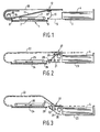
- the apparatus shown in Fig. 2 is suitable for processing originals printed on one side and for processing originals printed on two sides in two ways.
- the original is fed in the first discharge path 22 and conveyed therein until the trailing edge of that original has passed location 27.
- the direction of rotation of the conveyor roller 30 is then reversed and sheet deflector 31 is set in the broken-line position.
- the original is now returned via the second discharge path 28 to the exposure platen 24 for exposure of the other side. That original is then returned via the first discharge path 22 to the cassette, whereupon a subsequent original is fed from the cassette 23 to the exposure platen 24.
- the return path for directly returning an original after one side thereof has been exposed, to the exposure platen 24 for subsequent exposure of the other side of such original is thus formed by the first discharge path 22 and the second discharge path 28.
- This return path is denoted by a broken line in Fig. 2.
- FIG. 3 is a variant of the apparatus shown in Fig. 2, like parts having like references.
- the second discharge path 28 the conveyor path over the exposure platen 24, and that portion of the discharge path which, as considered in the direction of discharge, is situated past location 27, lie in one and the same plane, so that said path portions smoothly adjoin one another and the feed path 21 and the first discharge path 22 form an acute angle 32,33 respectively with the second discharge path 28.
- an original is discharged from the exposure platen 24 in the direction of the second discharge path 28 it is automatically guided into said path 28 and an original which is conveyed by sheet conveyor roller 30 in a direction opposite to the discharge direction is also guided automatically into path 28, i.e. without the use of sheet deflectors movable into two positions.
Landscapes
- Physics & Mathematics (AREA)
- General Physics & Mathematics (AREA)
- Exposure Or Original Feeding In Electrophotography (AREA)
- Holders For Sensitive Materials And Originals (AREA)
- Conveyance By Endless Belt Conveyors (AREA)
- Registering Or Overturning Sheets (AREA)
Applications Claiming Priority (2)
| Application Number | Priority Date | Filing Date | Title |
|---|---|---|---|
| NL8901873 | 1989-07-20 | ||
| NL8901873A NL8901873A (nl) | 1989-07-20 | 1989-07-20 | Inrichting voor het recirculeren van origineelbladen. |
Publications (2)
| Publication Number | Publication Date |
|---|---|
| EP0409309A1 true EP0409309A1 (de) | 1991-01-23 |
| EP0409309B1 EP0409309B1 (de) | 1994-06-01 |
Family
ID=19855070
Family Applications (1)
| Application Number | Title | Priority Date | Filing Date |
|---|---|---|---|
| EP90201826A Expired - Lifetime EP0409309B1 (de) | 1989-07-20 | 1990-07-09 | Vorlagen-Handhabungseinrichtung vom Umlauftyp |
Country Status (5)
| Country | Link |
|---|---|
| US (1) | US5074537A (de) |
| EP (1) | EP0409309B1 (de) |
| JP (1) | JP2839665B2 (de) |
| DE (1) | DE69009324T2 (de) |
| NL (1) | NL8901873A (de) |
Cited By (2)
| Publication number | Priority date | Publication date | Assignee | Title |
|---|---|---|---|---|
| EP0427178A3 (en) * | 1989-11-05 | 1991-11-27 | Canon Kabushiki Kaisha | Sheet original feeding apparatus and image forming system |
| US5192976A (en) * | 1989-11-05 | 1993-03-09 | Canon Kabushiki Kaisha | Sheet original feeding apparatus with detachable auxiliary feeder |
Families Citing this family (9)
| Publication number | Priority date | Publication date | Assignee | Title |
|---|---|---|---|---|
| JPH04304061A (ja) * | 1991-03-30 | 1992-10-27 | Toshiba Corp | 原稿読取り装置 |
| JP3018823B2 (ja) * | 1993-03-11 | 2000-03-13 | キヤノン株式会社 | 非循環式シート材搬送装置 |
| US5339139A (en) * | 1993-10-12 | 1994-08-16 | Xerox Corporation | Document feeder with positive document removal from imaging platen |
| US5430536A (en) * | 1993-10-12 | 1995-07-04 | Xerox Corporation | Automatic duplex and simplex document handler for electronic input |
| US5597157A (en) * | 1995-11-01 | 1997-01-28 | At&T Global Information Solutions Company | Document handling device for overturning a document |
| US6893048B2 (en) | 2003-07-01 | 2005-05-17 | Deere & Company | Flexible fender mount |
| US7413359B2 (en) * | 2006-01-19 | 2008-08-19 | Dell Products L.P. | Method and apparatus for printing |
| JP4789694B2 (ja) * | 2006-05-11 | 2011-10-12 | 由紀子 羽鳥 | おむつ取換え介護装置 |
| JP6608890B2 (ja) | 2017-09-12 | 2019-11-20 | ファナック株式会社 | 機械学習装置、ロボットシステム及び機械学習方法 |
Citations (4)
| Publication number | Priority date | Publication date | Assignee | Title |
|---|---|---|---|---|
| US4238126A (en) * | 1979-08-31 | 1980-12-09 | Xerox Corporation | Recirculating simplex/duplex document handler |
| EP0078166A2 (de) * | 1981-10-23 | 1983-05-04 | Xerox Corporation | Dokumenten-Zufuhrvorrichtung und diese enthaltende Reproduktionsgeräte |
| EP0078680A1 (de) * | 1981-10-29 | 1983-05-11 | Xerox Corporation | Vorrichtung für eine umlaufende Führung von Dokumenten |
| EP0211462A1 (de) * | 1985-08-02 | 1987-02-25 | Océ-Nederland B.V. | Vorrichtung zum Zuführen und Zurückführen von blattförmigen Vorlagen |
Family Cites Families (9)
| Publication number | Priority date | Publication date | Assignee | Title |
|---|---|---|---|---|
| DE2521932A1 (de) * | 1975-05-16 | 1976-11-25 | Agfa Gevaert Ag | Kopiergeraet |
| US4234180A (en) * | 1979-06-27 | 1980-11-18 | Xerox Corporation | Recirculating document handler configuration |
| US4419007A (en) * | 1982-06-14 | 1983-12-06 | Xerox Corporation | Multi-mode document handling system |
| JPS60159861A (ja) * | 1984-01-31 | 1985-08-21 | Ricoh Co Ltd | 原稿供給装置 |
| DE3606799A1 (de) * | 1985-03-04 | 1986-09-18 | Sharp K.K., Osaka | Dokumentzufuehrungsvorrichtung |
| JPS63295336A (ja) * | 1987-05-26 | 1988-12-01 | Sharp Corp | 循環式原稿送り装置 |
| US4884097A (en) * | 1987-12-24 | 1989-11-28 | Eastman Kodak Company | Duplex document handler |
| US4923190A (en) * | 1987-12-28 | 1990-05-08 | Ricoh Company, Ltd. | Original paper turning over and conveying out apparatus |
| US4881729A (en) * | 1988-06-06 | 1989-11-21 | Xerox Corporation | Recirculating document handler with integral SADH |
-
1989
- 1989-07-20 NL NL8901873A patent/NL8901873A/nl not_active Application Discontinuation
-
1990
- 1990-07-09 DE DE69009324T patent/DE69009324T2/de not_active Expired - Fee Related
- 1990-07-09 EP EP90201826A patent/EP0409309B1/de not_active Expired - Lifetime
- 1990-07-18 JP JP2190345A patent/JP2839665B2/ja not_active Expired - Lifetime
- 1990-07-18 US US07/553,627 patent/US5074537A/en not_active Expired - Lifetime
Patent Citations (4)
| Publication number | Priority date | Publication date | Assignee | Title |
|---|---|---|---|---|
| US4238126A (en) * | 1979-08-31 | 1980-12-09 | Xerox Corporation | Recirculating simplex/duplex document handler |
| EP0078166A2 (de) * | 1981-10-23 | 1983-05-04 | Xerox Corporation | Dokumenten-Zufuhrvorrichtung und diese enthaltende Reproduktionsgeräte |
| EP0078680A1 (de) * | 1981-10-29 | 1983-05-11 | Xerox Corporation | Vorrichtung für eine umlaufende Führung von Dokumenten |
| EP0211462A1 (de) * | 1985-08-02 | 1987-02-25 | Océ-Nederland B.V. | Vorrichtung zum Zuführen und Zurückführen von blattförmigen Vorlagen |
Cited By (3)
| Publication number | Priority date | Publication date | Assignee | Title |
|---|---|---|---|---|
| EP0427178A3 (en) * | 1989-11-05 | 1991-11-27 | Canon Kabushiki Kaisha | Sheet original feeding apparatus and image forming system |
| US5132741A (en) * | 1989-11-05 | 1992-07-21 | Canon Kabushiki Kaisha | Sheet original feeding apparatus and image forming system |
| US5192976A (en) * | 1989-11-05 | 1993-03-09 | Canon Kabushiki Kaisha | Sheet original feeding apparatus with detachable auxiliary feeder |
Also Published As
| Publication number | Publication date |
|---|---|
| DE69009324D1 (de) | 1994-07-07 |
| EP0409309B1 (de) | 1994-06-01 |
| DE69009324T2 (de) | 1994-10-13 |
| NL8901873A (nl) | 1991-02-18 |
| JP2839665B2 (ja) | 1998-12-16 |
| JPH0388683A (ja) | 1991-04-15 |
| US5074537A (en) | 1991-12-24 |
Similar Documents
| Publication | Publication Date | Title |
|---|---|---|
| US4639125A (en) | Automatic duplex copying type copying apparatus | |
| EP0409309B1 (de) | Vorlagen-Handhabungseinrichtung vom Umlauftyp | |
| US4916493A (en) | Exit roller reversal gate for duplex printing | |
| US5092579A (en) | Mechanism for preventing skew of cut paper sheet | |
| US5881350A (en) | Original guiding device | |
| US5666629A (en) | Multimode printer having sideway page inverter | |
| EP0313124B1 (de) | Vorrichtung zum Transportieren von Bögen | |
| US3984094A (en) | Separator card retriever | |
| GB2099796A (en) | Document circulating and conveying device for a copying machine | |
| US4819023A (en) | Automatic document feeder for automatically feeding a plurality of stacks of originals | |
| EP0464735B1 (de) | Dokumentenpositioniersystem mit zwei Betriebsarten | |
| JP3019545B2 (ja) | 記録装置 | |
| DE3921265A1 (de) | Fotokopiermaschine | |
| JP3287619B2 (ja) | シート搬送経路切換え装置 | |
| US6254087B1 (en) | Sheet transport device and sheet transport method | |
| US4875072A (en) | Automatic document feeder | |
| JP3355518B2 (ja) | 自動原稿送り装置 | |
| JP3098833B2 (ja) | 自動原稿搬送装置の制御方法 | |
| JPS6175768A (ja) | 複写機等の用紙排出装置 | |
| JPH06156817A (ja) | 画像形成装置の給紙装置 | |
| JP2888379B2 (ja) | 給紙装置 | |
| JPH04255869A (ja) | リサイクル原稿自動送り装置 | |
| JPS62290658A (ja) | 用紙送り方向変換装置 | |
| JP2892426B2 (ja) | 原稿搬送装置 | |
| JPH01162677A (ja) | 複写機の中間トレイへの用紙収容装置 |
Legal Events
| Date | Code | Title | Description |
|---|---|---|---|
| PUAI | Public reference made under article 153(3) epc to a published international application that has entered the european phase |
Free format text: ORIGINAL CODE: 0009012 |
|
| AK | Designated contracting states |
Kind code of ref document: A1 Designated state(s): DE FR GB IT NL |
|
| 17P | Request for examination filed |
Effective date: 19910717 |
|
| 17Q | First examination report despatched |
Effective date: 19930722 |
|
| GRAA | (expected) grant |
Free format text: ORIGINAL CODE: 0009210 |
|
| AK | Designated contracting states |
Kind code of ref document: B1 Designated state(s): DE FR GB IT NL |
|
| REF | Corresponds to: |
Ref document number: 69009324 Country of ref document: DE Date of ref document: 19940707 |
|
| ET | Fr: translation filed | ||
| ITF | It: translation for a ep patent filed | ||
| PLBE | No opposition filed within time limit |
Free format text: ORIGINAL CODE: 0009261 |
|
| STAA | Information on the status of an ep patent application or granted ep patent |
Free format text: STATUS: NO OPPOSITION FILED WITHIN TIME LIMIT |
|
| 26N | No opposition filed | ||
| NLT1 | Nl: modifications of names registered in virtue of documents presented to the patent office pursuant to art. 16 a, paragraph 1 |
Owner name: OCE-TECHNOLOGIES B.V. |
|
| PGFP | Annual fee paid to national office [announced via postgrant information from national office to epo] |
Ref country code: FR Payment date: 19990615 Year of fee payment: 10 |
|
| PGFP | Annual fee paid to national office [announced via postgrant information from national office to epo] |
Ref country code: GB Payment date: 19990618 Year of fee payment: 10 |
|
| PGFP | Annual fee paid to national office [announced via postgrant information from national office to epo] |
Ref country code: DE Payment date: 19990628 Year of fee payment: 10 |
|
| PGFP | Annual fee paid to national office [announced via postgrant information from national office to epo] |
Ref country code: NL Payment date: 19990714 Year of fee payment: 10 |
|
| PG25 | Lapsed in a contracting state [announced via postgrant information from national office to epo] |
Ref country code: GB Free format text: LAPSE BECAUSE OF NON-PAYMENT OF DUE FEES Effective date: 20000709 |
|
| PG25 | Lapsed in a contracting state [announced via postgrant information from national office to epo] |
Ref country code: NL Free format text: LAPSE BECAUSE OF NON-PAYMENT OF DUE FEES Effective date: 20010201 |
|
| GBPC | Gb: european patent ceased through non-payment of renewal fee |
Effective date: 20000709 |
|
| PG25 | Lapsed in a contracting state [announced via postgrant information from national office to epo] |
Ref country code: FR Free format text: LAPSE BECAUSE OF NON-PAYMENT OF DUE FEES Effective date: 20010330 |
|
| NLV4 | Nl: lapsed or anulled due to non-payment of the annual fee |
Effective date: 20010201 |
|
| REG | Reference to a national code |
Ref country code: FR Ref legal event code: ST |
|
| PG25 | Lapsed in a contracting state [announced via postgrant information from national office to epo] |
Ref country code: DE Free format text: LAPSE BECAUSE OF NON-PAYMENT OF DUE FEES Effective date: 20010501 |
|
| PG25 | Lapsed in a contracting state [announced via postgrant information from national office to epo] |
Ref country code: IT Free format text: LAPSE BECAUSE OF NON-PAYMENT OF DUE FEES Effective date: 20050709 |