EP0409344A2 - Membrane échangeuse de cations à grande stabilité - Google Patents
Membrane échangeuse de cations à grande stabilité Download PDFInfo
- Publication number
- EP0409344A2 EP0409344A2 EP90201932A EP90201932A EP0409344A2 EP 0409344 A2 EP0409344 A2 EP 0409344A2 EP 90201932 A EP90201932 A EP 90201932A EP 90201932 A EP90201932 A EP 90201932A EP 0409344 A2 EP0409344 A2 EP 0409344A2
- Authority
- EP
- European Patent Office
- Prior art keywords
- coating
- membrane
- inorganic material
- cation exchange
- layer
- Prior art date
- Legal status (The legal status is an assumption and is not a legal conclusion. Google has not performed a legal analysis and makes no representation as to the accuracy of the status listed.)
- Granted
Links
- 239000012528 membrane Substances 0.000 title claims abstract description 141
- 238000005341 cation exchange Methods 0.000 title claims abstract description 46
- 239000011248 coating agent Substances 0.000 claims abstract description 115
- 238000000576 coating method Methods 0.000 claims abstract description 115
- 239000002245 particle Substances 0.000 claims abstract description 75
- 229910010272 inorganic material Inorganic materials 0.000 claims abstract description 58
- 239000011147 inorganic material Substances 0.000 claims abstract description 58
- 230000003014 reinforcing effect Effects 0.000 claims abstract description 35
- 229920002313 fluoropolymer Polymers 0.000 claims abstract description 30
- 239000011164 primary particle Substances 0.000 claims abstract description 27
- 229920000642 polymer Polymers 0.000 claims abstract description 20
- 239000011230 binding agent Substances 0.000 claims abstract description 12
- 230000000737 periodic effect Effects 0.000 claims abstract description 7
- 150000001247 metal acetylides Chemical class 0.000 claims abstract description 5
- 150000004767 nitrides Chemical class 0.000 claims abstract description 5
- 239000004744 fabric Substances 0.000 claims description 33
- 125000001273 sulfonato group Chemical group [O-]S(*)(=O)=O 0.000 claims description 17
- 150000007942 carboxylates Chemical group 0.000 claims description 15
- 239000000203 mixture Substances 0.000 claims description 13
- NBVXSUQYWXRMNV-UHFFFAOYSA-N fluoromethane Chemical compound FC NBVXSUQYWXRMNV-UHFFFAOYSA-N 0.000 claims description 12
- TXEYQDLBPFQVAA-UHFFFAOYSA-N tetrafluoromethane Chemical compound FC(F)(F)F TXEYQDLBPFQVAA-UHFFFAOYSA-N 0.000 claims description 10
- RVTZCBVAJQQJTK-UHFFFAOYSA-N oxygen(2-);zirconium(4+) Chemical compound [O-2].[O-2].[Zr+4] RVTZCBVAJQQJTK-UHFFFAOYSA-N 0.000 claims description 8
- 229910001928 zirconium oxide Inorganic materials 0.000 claims description 8
- XUIMIQQOPSSXEZ-UHFFFAOYSA-N Silicon Chemical compound [Si] XUIMIQQOPSSXEZ-UHFFFAOYSA-N 0.000 claims description 2
- RTAQQCXQSZGOHL-UHFFFAOYSA-N Titanium Chemical compound [Ti] RTAQQCXQSZGOHL-UHFFFAOYSA-N 0.000 claims description 2
- QCWXUUIWCKQGHC-UHFFFAOYSA-N Zirconium Chemical compound [Zr] QCWXUUIWCKQGHC-UHFFFAOYSA-N 0.000 claims description 2
- 229910052710 silicon Inorganic materials 0.000 claims description 2
- 239000010703 silicon Substances 0.000 claims description 2
- 229910052719 titanium Inorganic materials 0.000 claims description 2
- 239000010936 titanium Substances 0.000 claims description 2
- 229910052726 zirconium Inorganic materials 0.000 claims description 2
- 239000002585 base Substances 0.000 abstract description 42
- 238000005868 electrolysis reaction Methods 0.000 abstract description 14
- 229910001514 alkali metal chloride Inorganic materials 0.000 abstract description 11
- 239000002759 woven fabric Substances 0.000 abstract description 11
- 230000002035 prolonged effect Effects 0.000 abstract description 8
- 210000004379 membrane Anatomy 0.000 description 87
- 239000002243 precursor Substances 0.000 description 48
- 239000007788 liquid Substances 0.000 description 23
- 238000000034 method Methods 0.000 description 19
- 239000000178 monomer Substances 0.000 description 18
- 239000010954 inorganic particle Substances 0.000 description 17
- 238000005507 spraying Methods 0.000 description 12
- 239000000243 solution Substances 0.000 description 10
- 229920001577 copolymer Polymers 0.000 description 8
- 239000007789 gas Substances 0.000 description 8
- 125000000524 functional group Chemical group 0.000 description 7
- OKKJLVBELUTLKV-UHFFFAOYSA-N Methanol Chemical compound OC OKKJLVBELUTLKV-UHFFFAOYSA-N 0.000 description 6
- HEMHJVSKTPXQMS-UHFFFAOYSA-M Sodium hydroxide Chemical compound [OH-].[Na+] HEMHJVSKTPXQMS-UHFFFAOYSA-M 0.000 description 6
- 230000007062 hydrolysis Effects 0.000 description 6
- 238000006460 hydrolysis reaction Methods 0.000 description 6
- LFQSCWFLJHTTHZ-UHFFFAOYSA-N Ethanol Chemical compound CCO LFQSCWFLJHTTHZ-UHFFFAOYSA-N 0.000 description 5
- 230000001476 alcoholic effect Effects 0.000 description 5
- 230000000052 comparative effect Effects 0.000 description 5
- 238000010438 heat treatment Methods 0.000 description 5
- 239000002904 solvent Substances 0.000 description 5
- 239000003513 alkali Substances 0.000 description 4
- 150000008044 alkali metal hydroxides Chemical class 0.000 description 4
- 229910052801 chlorine Inorganic materials 0.000 description 4
- 238000007796 conventional method Methods 0.000 description 4
- 238000001035 drying Methods 0.000 description 4
- 238000001125 extrusion Methods 0.000 description 4
- 229910021480 group 4 element Inorganic materials 0.000 description 4
- XLYOFNOQVPJJNP-UHFFFAOYSA-N water Substances O XLYOFNOQVPJJNP-UHFFFAOYSA-N 0.000 description 4
- KWYUFKZDYYNOTN-UHFFFAOYSA-M Potassium hydroxide Chemical compound [OH-].[K+] KWYUFKZDYYNOTN-UHFFFAOYSA-M 0.000 description 3
- BTANRVKWQNVYAZ-UHFFFAOYSA-N butan-2-ol Chemical compound CCC(C)O BTANRVKWQNVYAZ-UHFFFAOYSA-N 0.000 description 3
- 230000000694 effects Effects 0.000 description 3
- 238000005538 encapsulation Methods 0.000 description 3
- 229910052731 fluorine Inorganic materials 0.000 description 3
- 125000001153 fluoro group Chemical group F* 0.000 description 3
- 239000000543 intermediate Substances 0.000 description 3
- 238000005342 ion exchange Methods 0.000 description 3
- 238000000465 moulding Methods 0.000 description 3
- 238000003825 pressing Methods 0.000 description 3
- 230000002265 prevention Effects 0.000 description 3
- 230000001105 regulatory effect Effects 0.000 description 3
- ZAMOUSCENKQFHK-UHFFFAOYSA-N Chlorine atom Chemical compound [Cl] ZAMOUSCENKQFHK-UHFFFAOYSA-N 0.000 description 2
- IAZDPXIOMUYVGZ-UHFFFAOYSA-N Dimethylsulphoxide Chemical compound CS(C)=O IAZDPXIOMUYVGZ-UHFFFAOYSA-N 0.000 description 2
- UFHFLCQGNIYNRP-UHFFFAOYSA-N Hydrogen Chemical compound [H][H] UFHFLCQGNIYNRP-UHFFFAOYSA-N 0.000 description 2
- KFZMGEQAYNKOFK-UHFFFAOYSA-N Isopropanol Chemical compound CC(C)O KFZMGEQAYNKOFK-UHFFFAOYSA-N 0.000 description 2
- FAPWRFPIFSIZLT-UHFFFAOYSA-M Sodium chloride Chemical compound [Na+].[Cl-] FAPWRFPIFSIZLT-UHFFFAOYSA-M 0.000 description 2
- 239000002253 acid Substances 0.000 description 2
- 125000000217 alkyl group Chemical group 0.000 description 2
- 239000007864 aqueous solution Substances 0.000 description 2
- 125000004432 carbon atom Chemical group C* 0.000 description 2
- 150000001733 carboxylic acid esters Chemical group 0.000 description 2
- 239000000460 chlorine Substances 0.000 description 2
- 125000001309 chloro group Chemical group Cl* 0.000 description 2
- 125000004093 cyano group Chemical group *C#N 0.000 description 2
- 230000003247 decreasing effect Effects 0.000 description 2
- 229920001519 homopolymer Polymers 0.000 description 2
- 125000004435 hydrogen atom Chemical group [H]* 0.000 description 2
- 239000003014 ion exchange membrane Substances 0.000 description 2
- 150000002500 ions Chemical class 0.000 description 2
- 238000004519 manufacturing process Methods 0.000 description 2
- 239000000843 powder Substances 0.000 description 2
- BDERNNFJNOPAEC-UHFFFAOYSA-N propan-1-ol Chemical compound CCCO BDERNNFJNOPAEC-UHFFFAOYSA-N 0.000 description 2
- 230000002940 repellent Effects 0.000 description 2
- 239000005871 repellent Substances 0.000 description 2
- 239000000758 substrate Substances 0.000 description 2
- 239000000725 suspension Substances 0.000 description 2
- BFKJFAAPBSQJPD-UHFFFAOYSA-N tetrafluoroethene Chemical group FC(F)=C(F)F BFKJFAAPBSQJPD-UHFFFAOYSA-N 0.000 description 2
- 125000002023 trifluoromethyl group Chemical group FC(F)(F)* 0.000 description 2
- RRZIJNVZMJUGTK-UHFFFAOYSA-N 1,1,2-trifluoro-2-(1,2,2-trifluoroethenoxy)ethene Chemical compound FC(F)=C(F)OC(F)=C(F)F RRZIJNVZMJUGTK-UHFFFAOYSA-N 0.000 description 1
- LSNNMFCWUKXFEE-UHFFFAOYSA-M Bisulfite Chemical compound OS([O-])=O LSNNMFCWUKXFEE-UHFFFAOYSA-M 0.000 description 1
- WKBOTKDWSSQWDR-UHFFFAOYSA-N Bromine atom Chemical group [Br] WKBOTKDWSSQWDR-UHFFFAOYSA-N 0.000 description 1
- VEXZGXHMUGYJMC-UHFFFAOYSA-M Chloride anion Chemical compound [Cl-] VEXZGXHMUGYJMC-UHFFFAOYSA-M 0.000 description 1
- KZBUYRJDOAKODT-UHFFFAOYSA-N Chlorine Chemical compound ClCl KZBUYRJDOAKODT-UHFFFAOYSA-N 0.000 description 1
- LRHPLDYGYMQRHN-UHFFFAOYSA-N N-Butanol Chemical compound CCCCO LRHPLDYGYMQRHN-UHFFFAOYSA-N 0.000 description 1
- 229920000297 Rayon Polymers 0.000 description 1
- 208000036366 Sensation of pressure Diseases 0.000 description 1
- 238000002441 X-ray diffraction Methods 0.000 description 1
- 230000015572 biosynthetic process Effects 0.000 description 1
- 230000001680 brushing effect Effects 0.000 description 1
- 238000003490 calendering Methods 0.000 description 1
- 238000005336 cracking Methods 0.000 description 1
- 238000013480 data collection Methods 0.000 description 1
- 238000007872 degassing Methods 0.000 description 1
- 239000003792 electrolyte Substances 0.000 description 1
- 238000005265 energy consumption Methods 0.000 description 1
- 238000003912 environmental pollution Methods 0.000 description 1
- 239000000835 fiber Substances 0.000 description 1
- 150000004820 halides Chemical group 0.000 description 1
- 125000005843 halogen group Chemical group 0.000 description 1
- HCDGVLDPFQMKDK-UHFFFAOYSA-N hexafluoropropylene Chemical group FC(F)=C(F)C(F)(F)F HCDGVLDPFQMKDK-UHFFFAOYSA-N 0.000 description 1
- 229910052739 hydrogen Inorganic materials 0.000 description 1
- 239000001257 hydrogen Substances 0.000 description 1
- 230000003301 hydrolyzing effect Effects 0.000 description 1
- 239000000463 material Substances 0.000 description 1
- 125000001160 methoxycarbonyl group Chemical group [H]C([H])([H])OC(*)=O 0.000 description 1
- 230000004048 modification Effects 0.000 description 1
- 238000012986 modification Methods 0.000 description 1
- 229910000480 nickel oxide Inorganic materials 0.000 description 1
- 239000011368 organic material Substances 0.000 description 1
- GNRSAWUEBMWBQH-UHFFFAOYSA-N oxonickel Chemical compound [Ni]=O GNRSAWUEBMWBQH-UHFFFAOYSA-N 0.000 description 1
- 239000011236 particulate material Substances 0.000 description 1
- 229920005548 perfluoropolymer Polymers 0.000 description 1
- 229920000728 polyester Polymers 0.000 description 1
- 229940058401 polytetrafluoroethylene Drugs 0.000 description 1
- 239000004810 polytetrafluoroethylene Substances 0.000 description 1
- -1 polytetrafluoroethylene Polymers 0.000 description 1
- 229910052700 potassium Chemical group 0.000 description 1
- 239000002964 rayon Substances 0.000 description 1
- 238000009877 rendering Methods 0.000 description 1
- 239000011369 resultant mixture Substances 0.000 description 1
- 238000005185 salting out Methods 0.000 description 1
- 238000007493 shaping process Methods 0.000 description 1
- 229910052708 sodium Inorganic materials 0.000 description 1
- 239000011734 sodium Chemical group 0.000 description 1
- 239000011780 sodium chloride Substances 0.000 description 1
- 238000001179 sorption measurement Methods 0.000 description 1
- 239000007921 spray Substances 0.000 description 1
- 125000002128 sulfonyl halide group Chemical group 0.000 description 1
Images
Classifications
-
- C—CHEMISTRY; METALLURGY
- C08—ORGANIC MACROMOLECULAR COMPOUNDS; THEIR PREPARATION OR CHEMICAL WORKING-UP; COMPOSITIONS BASED THEREON
- C08J—WORKING-UP; GENERAL PROCESSES OF COMPOUNDING; AFTER-TREATMENT NOT COVERED BY SUBCLASSES C08B, C08C, C08F, C08G or C08H
- C08J5/00—Manufacture of articles or shaped materials containing macromolecular substances
- C08J5/20—Manufacture of shaped structures of ion-exchange resins
- C08J5/22—Films, membranes or diaphragms
- C08J5/2206—Films, membranes or diaphragms based on organic and/or inorganic macromolecular compounds
- C08J5/2275—Heterogeneous membranes
- C08J5/2281—Heterogeneous membranes fluorine containing heterogeneous membranes
-
- C—CHEMISTRY; METALLURGY
- C08—ORGANIC MACROMOLECULAR COMPOUNDS; THEIR PREPARATION OR CHEMICAL WORKING-UP; COMPOSITIONS BASED THEREON
- C08J—WORKING-UP; GENERAL PROCESSES OF COMPOUNDING; AFTER-TREATMENT NOT COVERED BY SUBCLASSES C08B, C08C, C08F, C08G or C08H
- C08J2327/00—Characterised by the use of homopolymers or copolymers of compounds having one or more unsaturated aliphatic radicals, each having only one carbon-to-carbon double bond, and at least one being terminated by a halogen; Derivatives of such polymers
- C08J2327/02—Characterised by the use of homopolymers or copolymers of compounds having one or more unsaturated aliphatic radicals, each having only one carbon-to-carbon double bond, and at least one being terminated by a halogen; Derivatives of such polymers not modified by chemical after-treatment
- C08J2327/12—Characterised by the use of homopolymers or copolymers of compounds having one or more unsaturated aliphatic radicals, each having only one carbon-to-carbon double bond, and at least one being terminated by a halogen; Derivatives of such polymers not modified by chemical after-treatment containing fluorine atoms
Definitions
- the present invention relates to a cation exchange membrane having high stability. More particularly, the present invention is concerned with a highly stable cation exchange membrane for use in the electrolysis of an alkali metal chloride, which comprises a reinforced base membrane comprised of at least one layer of a fluorocarbon polymer and a reinforcing woven fabric encapsulated therein and a coating disposed on at least one surface of the reinforced base membrane, wherein the coating comprises particles of a specific inorganic material having an average primary particle diameter as small as from 0.01 to 0.2 ⁇ m and a binder polymer.
- the coating containing particles of an inorganic material uniformly and strongly adheres to the surface of the reinforced base membrane, so that the inorganic material remains in the coating for a prolonged period of time. Accordingly, by the use of the cation exchange membrane of the present invention, the electrolysis of an alkali metal chloride can be stably performed at an advantageously low cell voltage for a prolonged period of time.
- the inorganic particle coating disposed on the surface of a cation exchange membrane has excellent effects on the electrolytic performance of the cation exchange membrane through the prevention of gas adsorption. To ensure the desired performance of the cation exchange membrane, it is requisite that the inorganic particle coating uniformly and strongly adhere to the surface of the membrane.
- the cation exchange membrane employed in the above-mentioned proposals is composed only of a fluorocarbon polymer and does not contain a reinforcing woven fabric.
- the cation exchange membrane of a fluorocarbon polymer now generally used on a commercial scale in the art has, encapsulated therein, a reinforcing woven fabric of a perfluoropolymer fiber for the purpose of imparting desired mechanical strength.
- a reinforced cation exchange membrane has rough surfaces ascribed to the shape of the surfaces of the reinforcing woven fabric.
- the coated cation exchange membrane disclosed in U.S. Patent No. 4,552,631 still has drawbacks. That is, the adhesion strength of the inorganic particle coating to the surface of the membrane is still not satisfactory and the inorganic particle coating is likely to come off during the electrolysis operated for a prolonged period of time.
- the particle diameter of the inorganic material particles which are actually used in the U.S. Patent is large. With such a large particle diameter as used in the U.S.
- the inorganic particle coating with a sufficient adhesion strength cannot be formed on the surface of a precursor membrane (a melt-fabricable membrane having functional groups convertible to ion exchange groups by hydrolysis) by a spraying method since the precursor membrane surface containing large diameter particles has water repellence properties inherent therein. Therefore, for obtaining a strongly adhered inorganic particle coating containing such large particles, the precursor membrane must be hydrolyzed and dried before a mixture of inorganic material particles and a binder is applied by spraying. This intermediate drying process is troublesome when the membrane is produced on a commercial scale.
- a cation exchange membrane comprising a membrane of a perfluorocarbon polymer reinforced with a woven fabric of perfluorocarbon polymer strands and a coating of an inorganic material uniformly and strongly adhering to the woven fabric-reinforced membrane.
- a cation exchange membrane comprising a base membrane of a perfluorocar bon polymer having sulfonate groups and/or carboxylate groups reinforced with a woven fabric of perfluorocarbon polymer strands and a coating of an inorganic material uniformly and strongly adhering to the base membrane, the present inventors have made extensive and intensive studies.
- a desired cation exchange membrane having a coating of an inorganic material uniformly and strongly adhering to a base membrane, which exhibits advantageously low cell voltage and high current efficiency can be obtained by the use of particles of at least one inorganic material selected from the group consisting of oxides, nitrides and carbides of elements belonging to group IV of the periodic table, which particles have an average primary particle diameter of from 0.01 to 0.2 ⁇ m.
- the present invention is based on this unexpected finding.
- a cation exchange membrane having a coating of inorganic material particles uniformly and strongly adhering to a base membrane, which coating can retain the inorganic material particles for a prolonged period of time.
- a cation exchange membrane comprising: a reinforced base membrane comprising at least one layer of a fluorocarbon polymer having pendant sulfonate groups, carboxylate groups or a mixture thereof and, encapsulated therein, a reinforcing fabric comprising warp and weft strands of a perfluorocarbon polymer, the warp and weft strands crossing each other to form window portions defined by the crossed warp and weft strands, and a coating disposed on at least one surface of the reinforced base membrane in an amount of from 0.01 to 10 mg/cm2 of the membrane surface, the coating comprising 30 to 95 % by weight, based on the total weight of the coating, of particles of at least one inorganic material selected from the group consisting of oxides, nitrides and carbides of elements belonging to group IV of the periodic table, the organic material particles having an average primary particle diameter of from 0.01 to 0.2 ⁇ m,
- the inorganic material to be used in the present invention for forming a coating together with a hydrophilic fluorocarbon polymer should be anticorrosive to electrolytes and hydrophilic, and is selected from the group consisting of oxides, nitrides and carbides of elements belonging to group IV of the periodic table. Preferred examples of such elements are zirconium, silicon and titanium. The most suitable inorganic material is zirconium oxide.
- the inorganic material is in the form of parti cles, which has an average primary particle diameter of from 0.01 to 0.2 ⁇ m, preferably from 0.02 to 0.08 ⁇ m.
- the terminology “primary particle” used herein means a particle which can be visually recognized as a minimum unit particle by means of an electron microscope.
- the primary particle reference can be made to, for example, page 98 of " Funtai no Hyomen Kaishitsu Gijutsu Shiryoshu (Technical Data Collection on Surface Modification of Particulate Materials) published by the Publishing Division of Soft Giken, Japan.
- the primary particles can clearly be discriminated from agglomerated particles and polymers on an electron photomicrograph (magnification: about 100,000).
- the average primary particle diameter can be obtained based on the diameters of the primary particles, which are measured by an electron microscope.
- 200 to 500 particles are usually measured in accordance with the ordinarily employed method for measuring particle diameter [reference may be made to, for example, " Funtai Kogaku Binran (Powder Engineering Handbook) edited by Funtai Kogakkai (Japanese Society of Powder Engineering) and published by Nikkan Kogyo Shimbun Sha, Japan, pages 1 to 50, 1986].
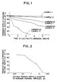
- the relationship between the average primary particle diameter of the inorganic material particles contained in a coating and the remaining ratio of the inorganic material particles in the coating after the electrolytic operation for a period of 8 months is shown in Fig. 2.
- the terminology "remaining ratio” used herein is defined as a weight percentage of the amount of the inorganic material particles remaining in the coating after the electrolytic operation to the amount of the inorganic material particles having been present in the coating before the electrolytic operation.
- the remaining ratio ( ⁇ , %) is determined as follows.
- group IV element The amount ( ⁇ 1, in terms of fluorescent X-ray intensity) of the element belonging to group IV of the periodic table (hereinafter referred to simply as "group IV element") contained in the inorganic material particles present in the coating of a sample cation exchange membrane, is measured by means of an X-ray microanalyzer [see “Manual for Fluorescent X-ray Analysis (page 45) published by Rigaku Denki Kogyo K.K., Japan, in 1982].
- the sample cation exchange membrane is incorporated in an electrolytic cell and electrolysis of an alkali metal chloride is performed for a predetermined period of time.
- the amount ( ⁇ 2, in terms of fluorescent X-ray intensity) of the group IV element contained in the inorganic material particles remaining in the coating irrespective of the electrolytic operation is measured by means of an X-ray microanalyzer.
- the remaining ratio of the inorganic material particles in the coating is excellent when the average primary particle diameter of inorganic material particles is 0.2 ⁇ m or less.
- the lower limit of the average primary particle diameter it is to be noted that the production of inorganic material particles having an average primary particle diameter of less than 0.01 ⁇ m is extremely difficult.
- the inventors of the present invention have also found that there is a relationship between the average primary particle diameter and the uniformity of the amount of the coating over the surface of the cation exchange membrane.
- the average primary particle diameter is in the range of from 0.01 to 0.2 ⁇ m, the uniformity of the amount of the coating over the surface of the cation exchange membrane is excellent.
- the amount of the coating per cm2 of the membrane surface is in the range of from 0.01 to 10 mg/cm2, preferably from 0.05 to 3 mg/cm2.
- the amount is smaller than 0.01 mg/cm2, the gas adhesion-preventive effect is insufficient.
- the electrolytic voltage is unfavorably high in an electrolytic cell.
- the amount of the coating per cm2 of the membrane surface is determined as follows. From a cation exchange membrane to be analyzed, a sample having a predetermined surface area (S, cm2), for example about 10 cm x 10 cm, is taken and the weight thereof (W1, mg) in the dry state is measured. The coating is removed from the reinforced base membrane of the sample, e.g., by immersing the sample in a 50:50 mixture of water and methanol and brushing. The resultant reinforced base membrane is dried, and the weight (W2, mg) thereof in measured. W c is calculated by the formula:
- the uniformity of the amount of the coating is evaluated in terms of the coefficient of variation (C v , %) calculated by the following formula: wherein S d represents a standard deviation of the amounts of the group IV element contained in the coating, as measured at 20 portions per dm2 of the membrane surface, which portions are arbitrarily taken in a region of the membrane which portion corresponds to an effective current flowing area, by means of an X-ray microanalyzer (see the reference mentioned above), and ⁇ represents an arithmetic average of the above-mentioned amounts of the group IV element.
- the coefficient of variation is advantageously as small as 6 % or less.
- the coefficient of variation is disadvantageously large.
- the amount of an inorganic material in the coating is in the range of from 30 to 95 wt%, preferably 70 to 90 wt%, based on the weight of the coating.
- the amount of an inorganic material in the coating is smaller than 30 wt%, sufficient gas absorption-preventive effect cannot be attained.
- the amount of the inorganic material is larger than 95 wt%, the mechanical strength of the coating is poor.
- a hydrophilic fluorocarbon polymer (homopolymer or copolymer) is used as the binder for bonding the inorganic material to the reinforced base membrane.
- a fluorocarbon copolymer having sulfonic acid or sulfonate groups.
- the reinforced base membrane for use in the cation exchange membrane of the present invention comprises at least one layer of a fluorocarbon polymer having pendant sulfonate groups, carboxylate groups or a mixture thereof as cation exchange groups.
- the cation exchange groups-containing fluorocarbon polymer is obtained by hydrolyzing a melt-fabricable fluorocarbon polymer comprising a main chain of a fluorocarbon and having functional groups convertible to cation exchange groups (hereinafter, the melt-fabricable fluorocarbon polymer being referred to as "precursor fluorocarbon polymer").
- the method for producing the precursor fluorocarbon polymer is not specifically limited, and with respect to the method, reference may be made to, for example, U.S. Patent Nos. 4,536,352, 4,131,740 and 3,282,875.
- the precursor fluorocarbon polymer having functional groups convertible to carboxylate groups can be produced by copolymerizing at least one monomer selectivelyed from the first group of monomers of formula (I) described above with at least one monomer selected from the following third groups of monomers of formula (III): wherein X3, n and m are as defined above and Y is a precursor group which can be converted by hydrolysis to a carboxylate group in the presence of an alkali medium.
- the above-mentioned precursor group which can be converted to a carboxylate group is selected from the group consisting of a carboxylic ester group represented by the formula -COOR wherein R represents a lower alkyl group having 1 to 4 carbon atoms, a cyano group represented by the formula -CN and an acid halide group represented by the formula -COG wherein G represents a halogen atom.
- the carboxylic ester group can preferably be used.
- An especially preferred monomer of the third group is be represented by the formula:
- the precursor fluorocarbon polymer having functional groups convertible to sulfonate groups can be produced by copolymerizing at least one monomer selected from the first group of monomers of formula (I) described above with at least one monomer selected from the following fourth group of monomers of formula (IV): wherein X3 is as defined above and J is a precursor group which can be converted by hydrolysis to a sulfonate group.
- the above-mentioned precursor group which can be converted to a sulfonate group is selected from the group consisting of a sulfonyl halide group represented by the formula -SO2X4 wherein X4 represents a fluorine atom, a chlorine atom or a bromine atom, and an alkylsulfone group represented by the formula -SO2R wherein R represents a lower alkyl group having 1 to 4 carbon atoms.
- Preferred monomers of the fourth group may be represented by the formula:
- the reinforced base membrane comprise two layers of a fluorocarbon polymer, and that one layer (hereinafter referred to as "layer A”) comprise a perfluorocarbon polymer containing carboxylate groups and be disposed on the cathode side in an electrolytic cell while the other layer (hereinafter referred to as “layer B”) comprise a perfluorocarbon polymer containing sulfonate groups and be disposed on the anode side in the electrolytic cell.
- layer A a perfluorocarbon polymer containing carboxylate groups and be disposed on the cathode side in an electrolytic cell
- layer B comprise a perfluorocarbon polymer containing sulfonate groups and be disposed on the anode side in the electrolytic cell.
- the equivalent weight of layer A is preferably in the range of from 1,000 to 1,600, depending on the concentration of sodium hydroxide employed in an electrolytic cell.
- the equivalent weight of layer A can be regulated by regulating the proportion of monomer (I) to monomer (III).
- the equivalent weight of layer B is preferably in the range of from 700 to 1,300, more preferably in the range of from 900 to 1,200.
- the desired equivalent weight of layer B can be obtained by regulating the proportion of monomer (I) to monomer (IV).
- the cation exchange membrane of the present invention may further comprise between layer A and layer B at least one layer of a fluorocarbon copolymer having an equivalent weight different from those of layers A and B.
- the cation exchange membrane of the present invention has a reinforcing fabric encapsulated therein which comprises warp and weft strands of a perfluorocarbon polymer.
- a reinforcing fabric encapsulated in the membrane for the purpose of improving the mechanical strength, the dimensional stability and the electrolytic performance stability of the membrane.
- the reinforcing fabric may be encapsulated in one of the layers.
- the reinforcing fabric may be encapsulated in two of the layers, bridging them.
- the reinforcing fabric be encapsulated in one layer having sulfonate groups which is to be disposed on the side of the anode in an electrolytic cell.
- the reinforcing fabric to be used in the present invention comprises warp and weft strands each prefera bly comprising a monofilament or a multifilament of a fluorocarbon polymer, such as a tetrafluoroethylene homopolymer and a copolymer of tetrafluoroethylene with hexafluoropropylene or a perfluorovinyl ether.
- the monofilament and the multifilament each have a size of from 30 to 400 denier, preferably from 50 to 200 denier.
- the reinforcing fabric may assume various forms.
- the texture of the fabric be coarse and the openness, as defined below, of the fabric be large.
- Preferred examples of reinforcing fabrics include a plain woven fabric and a leno woven fabric.
- openness means a ratio, as expressed in terms of a percentage, of the total area of the window portions defined by the crossed warp and weft strands of the reinforcing fabric to the overall area of the fabric.
- the above-mentioned total area of the window portions and the overall area of the fabric are readily measured on a photograph showing a plan view of the fabric.
- the openness of the reinforcing fabric is preferably in the range of from 50 to 95 %, more preferably in the range of from 60 to 90 %. When the openness is larger than 95 %, sufficient reinforcing effect cannot be obtained. On the other hand, when the openness is smaller than 50 %, the current shielding is disadvantageously increased so that the cell voltage is disadvantageously increased.
- the woven reinforcing fabric may further comprise sacrificial strands, such as those of a rayon and a polyester which are soluble in an alkali solution.
- sacrificial strands such as those of a rayon and a polyester which are soluble in an alkali solution.
- the thickness of the reinforcing fabric affects the easiness of the encapsulation of the reinforcing fabric in the fluorocarbon polymer layer or layers.
- the thickness of the reinforcing fabric is 150 ⁇ m or less, preferably 100 ⁇ m or less.
- the thickness of the reinforcing fabric may be controlled by the conventional calendering method.
- the thickness of layer A having carboxylate groups is generally in the range of from 1 to 80 ⁇ m, preferably from 5 to 50 ⁇ m, more preferably from 5 to 30 ⁇ m.
- the thickness of layer A is larger than 80 ⁇ m, the electric resistance is likely to become disadvantageously high in an electrolytic cell.
- the thickness of layer A is smaller than 1 ⁇ m, the electric resistance can be decreased, but the structure of the layer is likely to be undesirably non-uniform.
- the thickness of layer B having sulfonate groups it is preferred that layer B have a sufficient thickness so as to encapsulate the reinforcing fabric therein.
- the thickness of layer B be at least 25 ⁇ m, especially at least 50 ⁇ m. It is preferred that the upper limit of the thickness be 200 ⁇ m. When the thickness is larger than 200 ⁇ m, unfavorably high electrolytic voltage is caused in an electrolytic cell.
- the precursor fluorocarbon polymer having functional groups convertible to sulfonate groups, carboxylate groups or a mixture thereof is melt fabricable, and can be molded into a membrane (hereinafter referred to as "precursor membrane") by conventional methods, for example, by press molding using a heat press, shaping by means of rolls, extrusion molding, coextrusion molding, or the like. Of these, an extrusion molding is generally used on a commercial scale. In the present invention, when a precursor reinforced base membrane comprising two or more layers of fluorocarbon polymers is produced, a coextrusion molding is preferably used.
- the method for encapsulating the reinforcing fabric in the precursor fluorocarbon polymer layer or layers is not specifically limited, and with respect to the method for the encapsulation, reference may be made to, for example, U.S. Patent No. 4,324,606.
- the reinforcing fabric may be encapsulated by sandwiching the reinforcing fabric between two layers of precursor fluorocarbon polymers and heating the resultant layers while degassing to thereby obtain a desired precursor reinforced membrane.
- the coating is formed on the precursor reinforced base membrane by applying a coating liquid, as obtained by dispersing inorganic material particles having an average primary particle diameter of 0.01 to 0.2 ⁇ m in a fluorocarbon polymer solution, onto at least one surface of a precursor reinforced base membrane comprising a precursor fluorocarbon polymer having precursor ion exchange groups which can be converted to carboxylate groups, sulfonate groups or a mixture thereof by hydrolysis.
- the precursor reinforced base membrane has a critical surface tension as small as 20 dyn/cm while the above-mentioned coating liquid generally has a surface tension of 30 dyn/cm or more. This means that the precursor reinforced base membrane is highly repellent to the coating liquid. Thus, when it is attempted to form the coating on the precursor reinforced base membrane by means of a roll coater or the like, the coating liquid would be repelled so that any coating cannot be formed or the resultant coating would be extremely non-uniform in thickness. Therefore, it is infeasible to obtain a uniform coating having a satisfactory adhesion to the precursor reinforced base membrane.
- 1 to 20 % by weight preferably 1 to 5 % by weight of a fluorocarbon polymer
- an aqueous solution containing 20 % by weight or more, preferably 30 % by weight or more of an alcoholic solvent while heating.
- 1 to 50 % by weight, preferably 1 to 30 % by weight of inorganic material particles are added to the resultant solution and uniformly dispersed therein, thereby obtaining a coating liquid.
- the inorganic material particles can be prepared by a conventional means, such as a ball mill.
- alcoholic solvents include methanol, ethanol, n-propanol, isopropanol, n-butanol and 2-butanol.
- the inorganic material particles are agglomerated in the coating liquid.
- the average size of agglomerated inorganic material particles in the coating liquid is generally in the range of from 0.2 to 3.0 ⁇ m, preferably in the range of from 0.3 to 2.0 ⁇ m as measured using a particle size distribution-measuring centrifugal apparatus (Type CP-2, manufactured and sold by Shimadzu Corporation, Japan).
- a particle size distribution-measuring centrifugal apparatus Type CP-2, manufactured and sold by Shimadzu Corporation, Japan.
- the alcoholic solvent concentration of the aqueous alcoholic solvent solution is less than 20 % by weight and when the amount of the fluorocarbon polymer added to the aqueous alcoholic solvent solution is larger than 20 % by weight, based on the total weight of the fluorocarbon polymer and the solution, it is impossible to completely dissolve the fluorocarbon polymer in the aqueous solution.
- the amount of the inorganic material based on the amount of the coating liquid, is larger than 50 % by weight, it is infeasible to control the average size of agglomerated inorganic material particles in the coating liquid to 3.0 ⁇ m or less.
- the application of the coating liquid to at least one surface of a precursor reinforced base membrane can be performed by spraying. That is, the coating liquid is sprayed in the form of fine coating liquid particles having an average particle diameter of 5 to 40 ⁇ m in an amount of less than 50 ml/m2 ⁇ min.
- the coating liquid particles having an average particle diameter of less than 5 ⁇ m are sprayed, the ratio of the amount of the liquid particles adhering to the membrane surface to that of the sprayed liquid particles is disadvantageously small.
- the average particle diameter of the coating liquid particles is larger than 40 ⁇ m, a coating which is uniform in the amount of the coating over the surface cannot be obtained.
- the coating liquid When the coating liquid is sprayed in an amount of more than 50 ml/m2 ⁇ min, the sprayed liquid particles are likely to be coagulated on the surface of a precursor reinforced base membrane to thereby form a coating liquid layer which is repelled by the surface of the precursor reinforced base membrane.
- the spraying may be conducted by a conventional method using air.
- a conventional airless spraying method can also advantageously be used.
- an electrostatic airless spraying method can advantageously be used.
- the coating may be formed on only one outer surface or on both outer surfaces of the precursor reinforced base membrane.
- the coating is usually formed over the whole surface of the membrane.
- the coating be disposed on layer A, i.e., the fluorocarbon polymer layer having precursor groups convertible to carboxylate groups. Even when the coating is disposed on only one outer surface of the membrane, gas adhesion can advantageously be prevented in electrolysis so that the electrolytic voltage is advantageously not increased.
- the coating be also formed on the other surface of the precursor reinforced base membrane, because the increase of the electrolytic voltage can further be effectively prevented and the salting out of a alkali chloride within the membrane can be effectively prevented, leading to a prevention of damage of the membrane.
- the precursor reinforced base membrane described above has pendant functional groups in a melt-fabricable form, which per se do not have an ion exchange capability. Therefore, prior to the use of the membrane for producing an alkali metal hydroxide, it is necessary that the precursor reinforced base membrane be hydrolyzed by conventional methods using an acid or alkali so that all of the precursor functional groups are converted to ion exchange carboxylate and/or sulfonate groups.
- the thus obtained cation exchange membrane of the present invention is advantageously used in a narrow to zero gap cell, i.e., a cell having an anode and a cathode disposed at a spacing of about 1.5 mm or less therebetween.
- the electrolysis of an alkali metal chloride solution can be conducted under conditions such as conventionally employed. For example, an electrolysis can be conducted at a current density of 5 A/dm2 to 80 A/dm2 at 50 to 110 °C using an alkali metal chloride solution having an alkali metal chloride concentration of 140 g/liter to 290 g/liter which is charged in an anode compartment.
- the coating containing particles of an inorganic material uniformly and strongly adheres to the reinforced base membrane, so that the inorganic material can remain in the coating for a prolonged period of time. Accordingly, by the use of the cation exchange membrane of the present invention, the electrolysis of an alkali metal chloride can be stably performed at an advantageously low cell voltage for a prolonged period of time.
- the inorganic particle coating with a sufficient adhesion strength cannot be formed on the surface of a precursor membrane by a spraying method since the precursor membrane surface containing large diameter particles has water repellence properties inherent therein, and therefore, for obtaining a strongly adhered inorganic particle coating containing such large particles, the precursor membrane must be hydrolyzed and dried before a mixture of inorganic material particles and a binder is applied by spraying. This intermediate drying process is troublesome when the membrane is produced on a commercial scale.
- a mixture of inorganic material particles and a binder can advantageously be applied by spraying directly to the precursor membrane with attaining a sufficient adhesion strength, without necessity of the troublesome intermediate drying process as required in the process disclosed in U.S. Patent No. 4,552,631.
- a 18-mesh plain woven fabric of polytetrafluoroethylene strands each having a size of 200 denier is sandwiched between the above-prepared film A and film B and pressed under heating, thereby obtaining a precursor reinforced base membrane.
- the amount of the coating per cm2 of the membrane surface is 0.52 mg/cm2.
- the standard deviation of the amounts of the coating as defined above is as small as 0.03 mg/cm2, and the coefficient of variation as defined above is as small as 5.8 %.
- the coating is observed by an electron microscope, and it is found that the coating is uniform over the entire surface of the membrane and is free of cracks.
- the resultant precursor reinforced membrane having the coating is subjected to hydrolysis in a solution containing 30 % by weight of potassium hydroxide and 5 % by weight of dimethylsulfoxide.
- the resultant membrane is subjected to equilibrating treatment with a 0.1 N aqueous sodium hydroxide solution put in a beaker, and then heated at 90 °C for 2 hours, thereby obtaining a final cation exchange membrane. Coming-off of the coating is not observed by the equilibrating treatment.
- the thus obtained cation exchange membrane is set in an electrolytic cell in a manner such that the outer surface of film A having carboxylate groups is disposed on the side of a low hydrogen overpotential cathode and the surface of film B having sulfonate groups is disposed on the side of a low chlorine overpotential anode. Then, electrolysis is conducted at 90 °C at a current density of 40A/dm2 for 8 months while maintaining the concentration of sodium chloride in the anode compartment at 200 g/l.
- the remaining ratio of inorganic material particles in the coating is measured by an X-ray microanalyzer every month. The results are shown in Fig. 1. The remaining ratio after the electrolytic operation for 8 months is 97 %.
- Example 2 Substantially the same procedure as in Example 1 is repeated except that zirconium oxide having an average primary particle diameter of 0.2 ⁇ m is used, to thereby obtain a cation exchange membrane.
- the amount of the coating per cm2 of the membrane surface is 0.55 mg/cm2.
- the standard deviation of the amounts of the coating as defined above is as small as 0.03 mg/cm2, and the coefficient of variation as defined above is as small as 5.5 %.
- the remaining ratio of inorganic material particles is determined in the same manner as in Example 1. The results are shown in Fig. 1. The remaining ratio after the electrolytic operation for 8 months is 95 %.
- Example 2 Substantially the same procedure as in Example 1 is repeated except that zirconium oxides having average primary particle diameters of 0.7 ⁇ m, 5 ⁇ m, and 36 ⁇ m are, respectively, used in Comparative Examples 1, 2 and 3, to thereby obtain cation exchange membranes.
- the amounts of the coating per cm2 of the membrane surface in Comparative Examples 1, 2 and 3 are 0.51, 0.52 and 0.47 mg/cm2, respectively.
- the standard deviations of the amounts of the coating are 0.11, 0.39 and 0.61 mg/cm2, respectively, and the coefficients of variation are 21.6 %, 75 % and 129.8 %, respectively. As apparent from the results, the coefficient of variation is increased with an increase of a particle size.
- the remaining ratios of inorganic material particles are determined in the same manner as in Example 1. The results are shown in Fig. 1. The remaining ratios after the electrolytic operation for 8 months are 67 %, 56 %, and 0 %, respectively.
Landscapes
- Chemical & Material Sciences (AREA)
- Engineering & Computer Science (AREA)
- Manufacturing & Machinery (AREA)
- Inorganic Chemistry (AREA)
- Materials Engineering (AREA)
- Health & Medical Sciences (AREA)
- Chemical Kinetics & Catalysis (AREA)
- Medicinal Chemistry (AREA)
- Polymers & Plastics (AREA)
- Organic Chemistry (AREA)
- Manufacture Of Macromolecular Shaped Articles (AREA)
- Electrolytic Production Of Non-Metals, Compounds, Apparatuses Therefor (AREA)
Applications Claiming Priority (2)
| Application Number | Priority Date | Filing Date | Title |
|---|---|---|---|
| JP18256289 | 1989-07-17 | ||
| JP182562/89 | 1989-07-17 |
Publications (3)
| Publication Number | Publication Date |
|---|---|
| EP0409344A2 true EP0409344A2 (fr) | 1991-01-23 |
| EP0409344A3 EP0409344A3 (en) | 1991-12-11 |
| EP0409344B1 EP0409344B1 (fr) | 1995-03-08 |
Family
ID=16120444
Family Applications (1)
| Application Number | Title | Priority Date | Filing Date |
|---|---|---|---|
| EP90201932A Expired - Lifetime EP0409344B1 (fr) | 1989-07-17 | 1990-07-16 | Membrane échangeuse de cations à grande stabilité |
Country Status (5)
| Country | Link |
|---|---|
| US (1) | US5087345A (fr) |
| EP (1) | EP0409344B1 (fr) |
| JP (1) | JP3040799B2 (fr) |
| CA (1) | CA2021258C (fr) |
| DE (1) | DE69017539T2 (fr) |
Cited By (1)
| Publication number | Priority date | Publication date | Assignee | Title |
|---|---|---|---|---|
| EP0507235A3 (en) * | 1991-04-05 | 1993-01-13 | Asahi Glass Company Ltd. | Fluorine-containing cation exchange membrane for electrolysis |
Families Citing this family (12)
| Publication number | Priority date | Publication date | Assignee | Title |
|---|---|---|---|---|
| US5264090A (en) * | 1990-10-05 | 1993-11-23 | Asahi Kasei Kogyo Kabushiki Kaisha | Method for the electrolysis of an alkali metal chloride using a cation exchange membrane |
| US6354444B1 (en) * | 1997-07-01 | 2002-03-12 | Zenon Environmental Inc. | Hollow fiber membrane and braided tubular support therefor |
| JP5258137B2 (ja) * | 2000-09-27 | 2013-08-07 | 旭化成イーマテリアルズ株式会社 | パーフルオロカーボン系共重合体を含有する分散組成物 |
| DE102005023195A1 (de) * | 2005-05-19 | 2006-11-23 | Siemens Ag | Verfahren zur Erweiterung des Darstellungsbereiches einer Volumenaufnahme eines Objektbereiches |
| EP2242136A4 (fr) * | 2008-01-29 | 2011-12-28 | Tokuyama Corp | Membrane pour pile à combustible et processus pour sa production |
| WO2015098769A1 (fr) * | 2013-12-25 | 2015-07-02 | 旭硝子株式会社 | Procédé de production pour membrane échangeuse de cations fluorée |
| JP6400410B2 (ja) | 2014-09-25 | 2018-10-03 | 国立大学法人横浜国立大学 | 有機ケミカルハイドライド製造用電解セル |
| JP6981421B2 (ja) * | 2016-10-13 | 2021-12-15 | Agc株式会社 | アルカリ水電解用隔膜およびアルカリ水電解装置 |
| TWI721790B (zh) * | 2017-03-22 | 2021-03-11 | 日商旭化成股份有限公司 | 積層體、電解槽、電解槽之製造方法、積層體之更新方法、及捲繞體之製造方法 |
| CN110382740B (zh) * | 2017-03-22 | 2022-03-22 | 旭化成株式会社 | 电解用电极、层积体、卷绕体、电解槽、电解槽的制造方法、电极的更新方法、层积体的更新方法以及卷绕体的制造方法 |
| US10865282B2 (en) * | 2017-12-18 | 2020-12-15 | Asahi Kasei Kabushiki Kaisha | Ion exchange membrane, method for producing ion exchange membrane, and electrolyzer |
| US12334614B2 (en) | 2019-07-15 | 2025-06-17 | Compagnie Generale Des Etablissements Michelin | Polyvinylidene fluoride membrane support |
Family Cites Families (9)
| Publication number | Priority date | Publication date | Assignee | Title |
|---|---|---|---|---|
| AU535261B2 (en) * | 1979-11-27 | 1984-03-08 | Asahi Glass Company Limited | Ion exchange membrane cell |
| US4655886A (en) * | 1980-11-10 | 1987-04-07 | Asahi Glass Company, Ltd. | Ion exchange membrane cell and electrolysis with use thereof |
| DE3279507D1 (en) * | 1981-05-22 | 1989-04-13 | Asahi Glass Co Ltd | Ion exchange membrane electrolytic cell |
| JPS6017034B2 (ja) * | 1981-05-26 | 1985-04-30 | 旭硝子株式会社 | 新規な電解用陽イオン交換膜 |
| US4457815A (en) * | 1981-12-09 | 1984-07-03 | Ppg Industries, Inc. | Electrolytic cell, permionic membrane, and method of electrolysis |
| US4552631A (en) * | 1983-03-10 | 1985-11-12 | E. I. Du Pont De Nemours And Company | Reinforced membrane, electrochemical cell and electrolysis process |
| EP0253119A3 (fr) * | 1986-06-13 | 1989-07-19 | Asahi Glass Company Ltd. | Membrane échangeuse d'ions pour l'électrolyse |
| JP2533778B2 (ja) * | 1987-06-19 | 1996-09-11 | 旭化成工業株式会社 | 補強されたイオン交換膜及びその製造法 |
| JP2688902B2 (ja) * | 1987-08-26 | 1997-12-10 | 旭化成工業株式会社 | 強化されたイオン交換膜及びその製造法 |
-
1990
- 1990-07-16 CA CA002021258A patent/CA2021258C/fr not_active Expired - Lifetime
- 1990-07-16 US US07/552,890 patent/US5087345A/en not_active Expired - Lifetime
- 1990-07-16 DE DE69017539T patent/DE69017539T2/de not_active Expired - Lifetime
- 1990-07-16 EP EP90201932A patent/EP0409344B1/fr not_active Expired - Lifetime
- 1990-07-17 JP JP02187262A patent/JP3040799B2/ja not_active Expired - Lifetime
Cited By (3)
| Publication number | Priority date | Publication date | Assignee | Title |
|---|---|---|---|---|
| EP0507235A3 (en) * | 1991-04-05 | 1993-01-13 | Asahi Glass Company Ltd. | Fluorine-containing cation exchange membrane for electrolysis |
| US5264100A (en) * | 1991-04-05 | 1993-11-23 | Asahi Glass Company Ltd. | Fluorine-containing cation exchange membrane for electrolysis having a protruding porous base reinforcing material on one side thereof |
| CN1042751C (zh) * | 1991-04-05 | 1999-03-31 | 旭硝子株式会社 | 电解用的含氟阳离子交换膜 |
Also Published As
| Publication number | Publication date |
|---|---|
| EP0409344B1 (fr) | 1995-03-08 |
| CA2021258C (fr) | 1996-01-30 |
| US5087345A (en) | 1992-02-11 |
| CA2021258A1 (fr) | 1991-01-18 |
| DE69017539T2 (de) | 1995-11-30 |
| EP0409344A3 (en) | 1991-12-11 |
| DE69017539D1 (de) | 1995-04-13 |
| JP3040799B2 (ja) | 2000-05-15 |
| JPH03137136A (ja) | 1991-06-11 |
Similar Documents
| Publication | Publication Date | Title |
|---|---|---|
| EP0119080B1 (fr) | Membrane renforcée, cellule électrochimique et procédé d'électrolyse | |
| EP0409344A2 (fr) | Membrane échangeuse de cations à grande stabilité | |
| AU628580B2 (en) | A composite, porous diaphragm | |
| US5183545A (en) | Electrolytic cell with composite, porous diaphragm | |
| US6110333A (en) | Composite membrane with highly crystalline porous support | |
| CA1325195C (fr) | Methode pour la production d'un hydroxyde de metal alcalin | |
| CA1339685C (fr) | Membrane d'echanges ioniques renforcee et procede de fabrication de cette membrane | |
| CA1273315A (fr) | Production d'hydroxyde de potassium | |
| JP7746994B2 (ja) | 膜電極接合体、固体高分子電解質膜、水電解装置および電解水素化装置 | |
| US4990228A (en) | Cation exchange membrane and use | |
| JPS59174627A (ja) | 強化されていない膜、電気化学的槽、および電解方法 | |
| JP2533778B2 (ja) | 補強されたイオン交換膜及びその製造法 | |
| US4496451A (en) | Ion exchange membrane manufacture for electrolytic cell | |
| US4988364A (en) | Coated cation exchange yarn and process | |
| CA1234551A (fr) | Membrane electrolytique laminee avec echange cationique, renfermant un polymere fluore dote de groupes d'acide carboxylique | |
| EP0388670B1 (fr) | Membrane échangeuse de cations renforcée et procédé | |
| CA1206439A (fr) | Membrane echangeuse d'ions en polymere fluore avec couche poreuse ne faisant pas electrode | |
| US4996098A (en) | Coated cation exchange fabric and process | |
| EP0479392B1 (fr) | Méthode pour l'électrolyse de chlorure d'un métal alcalin utilisant une membrane échangeuse de cations | |
| CA1223842A (fr) | Membrane electrolytique armee a couches de sulfonate et de carboxylate | |
| EP0412589B1 (fr) | Membrane échangeuse de cations ayant une grande durabilité | |
| CA2010843A1 (fr) | Membranes echangeuse de cations renforces d'un tissu echangeur de cations | |
| JPH04297591A (ja) | アルカリ金属塩化物電解用イオン交換膜 |
Legal Events
| Date | Code | Title | Description |
|---|---|---|---|
| PUAI | Public reference made under article 153(3) epc to a published international application that has entered the european phase |
Free format text: ORIGINAL CODE: 0009012 |
|
| AK | Designated contracting states |
Kind code of ref document: A2 Designated state(s): BE DE FR GB IT NL |
|
| 17P | Request for examination filed |
Effective date: 19901221 |
|
| PUAL | Search report despatched |
Free format text: ORIGINAL CODE: 0009013 |
|
| AK | Designated contracting states |
Kind code of ref document: A3 Designated state(s): BE DE FR GB IT NL |
|
| 17Q | First examination report despatched |
Effective date: 19930802 |
|
| GRAA | (expected) grant |
Free format text: ORIGINAL CODE: 0009210 |
|
| AK | Designated contracting states |
Kind code of ref document: B1 Designated state(s): BE DE FR GB IT NL |
|
| REF | Corresponds to: |
Ref document number: 69017539 Country of ref document: DE Date of ref document: 19950413 |
|
| ET | Fr: translation filed | ||
| ITF | It: translation for a ep patent filed | ||
| PLBE | No opposition filed within time limit |
Free format text: ORIGINAL CODE: 0009261 |
|
| STAA | Information on the status of an ep patent application or granted ep patent |
Free format text: STATUS: NO OPPOSITION FILED WITHIN TIME LIMIT |
|
| 26N | No opposition filed | ||
| REG | Reference to a national code |
Ref country code: GB Ref legal event code: IF02 |
|
| PGFP | Annual fee paid to national office [announced via postgrant information from national office to epo] |
Ref country code: BE Payment date: 20090619 Year of fee payment: 20 |
|
| PGFP | Annual fee paid to national office [announced via postgrant information from national office to epo] |
Ref country code: FR Payment date: 20090710 Year of fee payment: 20 |
|
| PGFP | Annual fee paid to national office [announced via postgrant information from national office to epo] |
Ref country code: DE Payment date: 20090709 Year of fee payment: 20 Ref country code: NL Payment date: 20090715 Year of fee payment: 20 Ref country code: GB Payment date: 20090715 Year of fee payment: 20 |
|
| PGFP | Annual fee paid to national office [announced via postgrant information from national office to epo] |
Ref country code: IT Payment date: 20090717 Year of fee payment: 20 |
|
| REG | Reference to a national code |
Ref country code: NL Ref legal event code: V4 Effective date: 20100716 |
|
| BE20 | Be: patent expired |
Owner name: *ASAHI KASEI KOGYO K.K. Effective date: 20100716 |
|
| REG | Reference to a national code |
Ref country code: GB Ref legal event code: PE20 Expiry date: 20100715 |
|
| PG25 | Lapsed in a contracting state [announced via postgrant information from national office to epo] |
Ref country code: NL Free format text: LAPSE BECAUSE OF EXPIRATION OF PROTECTION Effective date: 20100716 |
|
| PG25 | Lapsed in a contracting state [announced via postgrant information from national office to epo] |
Ref country code: GB Free format text: LAPSE BECAUSE OF EXPIRATION OF PROTECTION Effective date: 20100715 |
|
| PG25 | Lapsed in a contracting state [announced via postgrant information from national office to epo] |
Ref country code: DE Free format text: LAPSE BECAUSE OF EXPIRATION OF PROTECTION Effective date: 20100716 |