EP0409405B1 - Elément de combustible nucléaire et procédé pour sa fabrication - Google Patents
Elément de combustible nucléaire et procédé pour sa fabrication Download PDFInfo
- Publication number
- EP0409405B1 EP0409405B1 EP90306606A EP90306606A EP0409405B1 EP 0409405 B1 EP0409405 B1 EP 0409405B1 EP 90306606 A EP90306606 A EP 90306606A EP 90306606 A EP90306606 A EP 90306606A EP 0409405 B1 EP0409405 B1 EP 0409405B1
- Authority
- EP
- European Patent Office
- Prior art keywords
- fuel
- metal
- stainless steel
- expendable
- zirconium
- Prior art date
- Legal status (The legal status is an assumption and is not a legal conclusion. Google has not performed a legal analysis and makes no representation as to the accuracy of the status listed.)
- Expired - Lifetime
Links
- 238000000034 method Methods 0.000 title claims description 10
- 239000003758 nuclear fuel Substances 0.000 title description 9
- 239000000446 fuel Substances 0.000 claims description 168
- QCWXUUIWCKQGHC-UHFFFAOYSA-N Zirconium Chemical compound [Zr] QCWXUUIWCKQGHC-UHFFFAOYSA-N 0.000 claims description 50
- 229910052751 metal Inorganic materials 0.000 claims description 48
- 239000002184 metal Substances 0.000 claims description 48
- 229910001220 stainless steel Inorganic materials 0.000 claims description 35
- 239000010935 stainless steel Substances 0.000 claims description 34
- 229910001092 metal group alloy Inorganic materials 0.000 claims description 29
- 229910052726 zirconium Inorganic materials 0.000 claims description 28
- 229910052778 Plutonium Inorganic materials 0.000 claims description 26
- OYEHPCDNVJXUIW-UHFFFAOYSA-N plutonium atom Chemical compound [Pu] OYEHPCDNVJXUIW-UHFFFAOYSA-N 0.000 claims description 26
- 229910052770 Uranium Inorganic materials 0.000 claims description 25
- JFALSRSLKYAFGM-UHFFFAOYSA-N uranium(0) Chemical compound [U] JFALSRSLKYAFGM-UHFFFAOYSA-N 0.000 claims description 25
- 238000005275 alloying Methods 0.000 claims description 24
- 238000005253 cladding Methods 0.000 claims description 12
- 230000003993 interaction Effects 0.000 claims description 6
- 230000002093 peripheral effect Effects 0.000 claims description 6
- RTAQQCXQSZGOHL-UHFFFAOYSA-N Titanium Chemical compound [Ti] RTAQQCXQSZGOHL-UHFFFAOYSA-N 0.000 claims description 5
- 239000010936 titanium Substances 0.000 claims description 5
- 229910052719 titanium Inorganic materials 0.000 claims description 5
- ZOKXTWBITQBERF-UHFFFAOYSA-N Molybdenum Chemical compound [Mo] ZOKXTWBITQBERF-UHFFFAOYSA-N 0.000 claims description 4
- 229910052750 molybdenum Inorganic materials 0.000 claims description 4
- 239000011733 molybdenum Substances 0.000 claims description 4
- 229910052758 niobium Inorganic materials 0.000 claims description 4
- 239000010955 niobium Substances 0.000 claims description 4
- GUCVJGMIXFAOAE-UHFFFAOYSA-N niobium atom Chemical compound [Nb] GUCVJGMIXFAOAE-UHFFFAOYSA-N 0.000 claims description 4
- 230000002401 inhibitory effect Effects 0.000 claims description 3
- 230000008018 melting Effects 0.000 description 31
- 238000002844 melting Methods 0.000 description 31
- 229910045601 alloy Inorganic materials 0.000 description 24
- 239000000956 alloy Substances 0.000 description 24
- 239000000203 mixture Substances 0.000 description 20
- 230000004992 fission Effects 0.000 description 11
- 239000000463 material Substances 0.000 description 11
- 239000004615 ingredient Substances 0.000 description 10
- XEEYBQQBJWHFJM-UHFFFAOYSA-N Iron Chemical compound [Fe] XEEYBQQBJWHFJM-UHFFFAOYSA-N 0.000 description 8
- 150000002739 metals Chemical class 0.000 description 6
- 239000000126 substance Substances 0.000 description 6
- 230000015572 biosynthetic process Effects 0.000 description 5
- 239000000919 ceramic Substances 0.000 description 5
- 239000002826 coolant Substances 0.000 description 5
- 238000009792 diffusion process Methods 0.000 description 5
- 230000000694 effects Effects 0.000 description 5
- 238000005755 formation reaction Methods 0.000 description 5
- 229910001338 liquidmetal Inorganic materials 0.000 description 5
- 230000008961 swelling Effects 0.000 description 5
- 230000005496 eutectics Effects 0.000 description 4
- 239000007789 gas Substances 0.000 description 4
- 229910052742 iron Inorganic materials 0.000 description 4
- 229910001256 stainless steel alloy Inorganic materials 0.000 description 4
- ZSLUVFAKFWKJRC-IGMARMGPSA-N 232Th Chemical compound [232Th] ZSLUVFAKFWKJRC-IGMARMGPSA-N 0.000 description 3
- 229910052776 Thorium Inorganic materials 0.000 description 3
- 229910001093 Zr alloy Inorganic materials 0.000 description 3
- 229910002056 binary alloy Inorganic materials 0.000 description 3
- 238000006243 chemical reaction Methods 0.000 description 3
- 239000000470 constituent Substances 0.000 description 3
- 239000012611 container material Substances 0.000 description 3
- 239000000047 product Substances 0.000 description 3
- 230000009257 reactivity Effects 0.000 description 3
- 238000012546 transfer Methods 0.000 description 3
- NBWXXYPQEPQUSB-UHFFFAOYSA-N uranium zirconium Chemical compound [Zr].[Zr].[U] NBWXXYPQEPQUSB-UHFFFAOYSA-N 0.000 description 3
- 239000011800 void material Substances 0.000 description 3
- AVMSOXISNPVTNY-UHFFFAOYSA-N [Zr].[U].[Pu] Chemical compound [Zr].[U].[Pu] AVMSOXISNPVTNY-UHFFFAOYSA-N 0.000 description 2
- 239000000654 additive Substances 0.000 description 2
- 230000000996 additive effect Effects 0.000 description 2
- TVFDJXOCXUVLDH-UHFFFAOYSA-N caesium atom Chemical compound [Cs] TVFDJXOCXUVLDH-UHFFFAOYSA-N 0.000 description 2
- 238000013461 design Methods 0.000 description 2
- 239000000155 melt Substances 0.000 description 2
- OOAWCECZEHPMBX-UHFFFAOYSA-N oxygen(2-);uranium(4+) Chemical compound [O-2].[O-2].[U+4] OOAWCECZEHPMBX-UHFFFAOYSA-N 0.000 description 2
- WJWSFWHDKPKKES-UHFFFAOYSA-N plutonium uranium Chemical compound [U].[Pu] WJWSFWHDKPKKES-UHFFFAOYSA-N 0.000 description 2
- 230000005855 radiation Effects 0.000 description 2
- FCTBKIHDJGHPPO-UHFFFAOYSA-N uranium dioxide Inorganic materials O=[U]=O FCTBKIHDJGHPPO-UHFFFAOYSA-N 0.000 description 2
- 229910000851 Alloy steel Inorganic materials 0.000 description 1
- 229910052684 Cerium Inorganic materials 0.000 description 1
- VYZAMTAEIAYCRO-UHFFFAOYSA-N Chromium Chemical compound [Cr] VYZAMTAEIAYCRO-UHFFFAOYSA-N 0.000 description 1
- 241000237858 Gastropoda Species 0.000 description 1
- DGAQECJNVWCQMB-PUAWFVPOSA-M Ilexoside XXIX Chemical compound C[C@@H]1CC[C@@]2(CC[C@@]3(C(=CC[C@H]4[C@]3(CC[C@@H]5[C@@]4(CC[C@@H](C5(C)C)OS(=O)(=O)[O-])C)C)[C@@H]2[C@]1(C)O)C)C(=O)O[C@H]6[C@@H]([C@H]([C@@H]([C@H](O6)CO)O)O)O.[Na+] DGAQECJNVWCQMB-PUAWFVPOSA-M 0.000 description 1
- 229910001066 Pu alloy Inorganic materials 0.000 description 1
- KEAYESYHFKHZAL-UHFFFAOYSA-N Sodium Chemical compound [Na] KEAYESYHFKHZAL-UHFFFAOYSA-N 0.000 description 1
- LZJLRRQFSBMOGR-UHFFFAOYSA-N [Zr].[Pu] Chemical compound [Zr].[Pu] LZJLRRQFSBMOGR-UHFFFAOYSA-N 0.000 description 1
- 230000002411 adverse Effects 0.000 description 1
- 230000009286 beneficial effect Effects 0.000 description 1
- 229910052792 caesium Inorganic materials 0.000 description 1
- GWXLDORMOJMVQZ-UHFFFAOYSA-N cerium Chemical compound [Ce] GWXLDORMOJMVQZ-UHFFFAOYSA-N 0.000 description 1
- 229910052804 chromium Inorganic materials 0.000 description 1
- 239000011651 chromium Substances 0.000 description 1
- 238000011109 contamination Methods 0.000 description 1
- 238000005260 corrosion Methods 0.000 description 1
- 230000007797 corrosion Effects 0.000 description 1
- 230000002939 deleterious effect Effects 0.000 description 1
- 238000004090 dissolution Methods 0.000 description 1
- 238000011156 evaluation Methods 0.000 description 1
- 239000011888 foil Substances 0.000 description 1
- 238000010438 heat treatment Methods 0.000 description 1
- 230000006872 improvement Effects 0.000 description 1
- 238000005259 measurement Methods 0.000 description 1
- 230000007246 mechanism Effects 0.000 description 1
- 229910044991 metal oxide Inorganic materials 0.000 description 1
- 230000005012 migration Effects 0.000 description 1
- 238000013508 migration Methods 0.000 description 1
- 230000035515 penetration Effects 0.000 description 1
- 230000035699 permeability Effects 0.000 description 1
- 238000010587 phase diagram Methods 0.000 description 1
- 230000003334 potential effect Effects 0.000 description 1
- 229910052708 sodium Inorganic materials 0.000 description 1
- 239000011734 sodium Substances 0.000 description 1
- 239000007787 solid Substances 0.000 description 1
- 239000013589 supplement Substances 0.000 description 1
- 230000001052 transient effect Effects 0.000 description 1
- XLYOFNOQVPJJNP-UHFFFAOYSA-N water Substances O XLYOFNOQVPJJNP-UHFFFAOYSA-N 0.000 description 1
- -1 zirconium metals Chemical class 0.000 description 1
Images

Classifications
-
- G—PHYSICS
- G21—NUCLEAR PHYSICS; NUCLEAR ENGINEERING
- G21C—NUCLEAR REACTORS
- G21C3/00—Reactor fuel elements and their assemblies; Selection of substances for use as reactor fuel elements
- G21C3/02—Fuel elements
- G21C3/04—Constructional details
- G21C3/16—Details of the construction within the casing
- G21C3/18—Internal spacers or other non-active material within the casing, e.g. compensating for expansion of fuel rods or for compensating excess reactivity
-
- Y—GENERAL TAGGING OF NEW TECHNOLOGICAL DEVELOPMENTS; GENERAL TAGGING OF CROSS-SECTIONAL TECHNOLOGIES SPANNING OVER SEVERAL SECTIONS OF THE IPC; TECHNICAL SUBJECTS COVERED BY FORMER USPC CROSS-REFERENCE ART COLLECTIONS [XRACs] AND DIGESTS
- Y02—TECHNOLOGIES OR APPLICATIONS FOR MITIGATION OR ADAPTATION AGAINST CLIMATE CHANGE
- Y02E—REDUCTION OF GREENHOUSE GAS [GHG] EMISSIONS, RELATED TO ENERGY GENERATION, TRANSMISSION OR DISTRIBUTION
- Y02E30/00—Energy generation of nuclear origin
- Y02E30/30—Nuclear fission reactors
Definitions
- This invention relates to fuel elements containing fissionable fuel material for use in nuclear reactors.
- the invention is specifically directed to an improvement in nuclear reactor fuel elements containing fissionable fuel in metallic form and alloys of mixtures of metals which are housed within stainless steel containers.
- Fissionable nuclear fuel for nuclear reactors typically comprises one of two principal chemical forms.
- Ceramic or non-metallic oxides of fissionable and/or fertile element(s) such as uranium, plutonium or thorium, and mixtures thereof.
- This category of ceramic or oxide fuels are disclosed, for example, in U.S. Patents US.A. 4,200,492, issued April 29, 1980, and US.A. 4,372,817, issued February 8, 1983.
- Ceramic fuels commonly comprising uranium dioxide are most frequently used in contemporary commercial electrical power generating, water cooled and moderated nuclear reactors.
- Typical oxide forms of fuel such as uranium dioxide have melting temperatures of approximately 2760 degrees C (5000 degrees F).
- Ceramic or non-metallic fuels however suffer from low thermal conductivity and lower fissionable atoms per unit volume, among other shortcomings.
- the other principal type of nuclear reactor fuel comprises fissionable elements such as uranium, plutonium and thorium, and mixtures thereof, in metallic, non-oxide form.
- fissionable elements such as uranium, plutonium and thorium, and mixtures thereof, in metallic, non-oxide form.
- this category comprises uranium, plutonium, etc. metal and mixtures of such metals, namely alloys of such metals.
- Fissionable fuel materials in metal form have a long history in the nuclear reactor field, but due to significant shortcomings have currently been used primarily in the so-called breeder type of reactors utilizing liquid metal coolants.
- the primary handicaps in the use of metallic fissionable material as fuel are their relatively low melting temperatures and accompanying loss of structural characteristics such as tensile strength at moderately low temperatures, and high degree of reactivity with other elements including susceptibility to corrosion.
- uranium the most prevalent fissionable fuel material, as a metal melts at only 1132 degrees C (2070 degrees F), and an alloyed metal fuel containing uranium and plutonium normally have even lower melting temperatures, such as about 610 degrees C (1130 degrees F) for an 88 weight percent uranium and 12 weight percent plutonium alloy.
- Fissionable fuels in metal form provide excellent thermal conductivity for highly efficient heat transfer, and maximum concentration of fissionable atoms per unit volume, among other attributes. Thus, more power can be produced per unit size with metallic fuel, and more efficiently conveyed to the heat carrying coolant.
- Alloying mixtures of uranium metal and/or plutonium metal have been proposed and used to enhance metal fuels and overcome such shortcomings.
- small amounts of alloying metals such as molybdenum, niobium, titanium, zirconium, or chromium, have been used to stabilize phase structures and in turn the properties attributable thereto in metallic fuels.
- Zirconium is also included as an alloying component in such metallic fuels to provide an elevated solidus temperature for the fuel and to enhance its chemical compatibility with stainless steel which is commonly employed in fuel containers for service in liquid metal cooled nuclear reactors.
- One significant aspect of this chemical redistribution of the alloyed ingredients such as zirconium is the inward migration of the zirconium metal to the inner or central area of the body of fuel with an accompanying increase in the solidus temperature of the inner or central area and correspondingly a reduced solidus temperature in the outer or peripheral area of the unit.
- the melting conditions of the remaining alloying ingredients, such as uranium and/or plutonium, in the peripheral area of the fuel body are lowered, and the effect of the added zirconium to avoid low melting phase formation is reduced or negated.
- a lower melting condition of the surface portions of fuel units increase the potential for chemical interaction with adjoining materials.
- the body of fuel material typically in the form of long thin rods and sometimes referred to as slugs, is provided with a cross-sectional dimension substantially less than the internal cross-sectional area of the container housing the fuel to accommodate the increased volume of the resulting irradiation gas bloated body of fuel.
- the present invention deals with methods of inhibiting an interaction between a metal alloy fissionable fuel for a nuclear reactor and a stainless steel container for the fuel by compensating for the chemical redistribution of beneficial alloying ingredients in the metal alloy fuel according to claims 1 and 5, and a nuclear fuel element obtained by said methods.
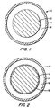
- Fuel element 10 comprises an elongated body(s) of fuel 12, such as a rod sometimes referred to as a pin or slug, containing a fissionable material in the form of metal, or a mixture of metals or alloy.
- Typical fissionable fuels in metal form comprise uranium, plutonium and thorium, which can be employed alone or alloyed.
- Most commonly such fuels primarily comprise uranium metal, and currently a preferred fuel comprises combinations of a major portion of uranium alloyed with a minor portion of plutonium, for example about 60 to about 98 percent weight uranium metal with about 2 to about 40 percent weight plutonium metal.
- a preferred metal fuel alloy under consideration for commercial service comprises an alloyed composition of about 64 weight percent of uranium metal, about 26 weight percent of plutonium metal and about 10 weight percent of zirconium. Such an alloy has a melting point of about 1020 degrees C (1868 degrees F).
- the elongated body of metallic fuel 12, or several sections of fuel bodies or rods, is housed within a sealed, tube-like metal container 14, sometimes referred to as a "fuel cladding".
- Sealed container 14 isolates the fuel body 12 from the coolant which flows over the exterior surface of the fuel element 10 to transfer heat away therefrom, protecting the fuel from reaction with or contamination from the coolant. Moreover the container seals in fission products and precludes their escape out into the coolant.
- Typical liquid metal cooled nuclear reactors such as the system disclosed in U.S. Patent US.A. 4,508,677, issued April 2, 1985, conventionally use stainless steel for their metal fuel containers.
- Stainless steel alloys comprising those marketed under the commercial designations HT9 or D9 are currently the preferred compositions for the service.
- Typical alloy compositions for these stainless steel are shown in the following Table I.
- the metal fuel body(s) 12 is designed in configurational dimensions for radial expansion of about 25 to 30 percent in volume due primarily to internally generated, fission produced gases.
- the initially produced metal fuel units are of substantially smaller cross-sectional diameter than the internal cross-sectional area within the fuel container 14.
- This difference in cross-sectional dimensions between the metal fuel body 12 initially and the fuel container 14 leaves an intermediate void space 16, or gap, between the exterior surface of the fuel body 12 and the interior surface of the fuel container 14.
- This initial intermediate space 16 is designed to accommodate the extensive expansion of the fuel units 12 attributable to the gases produced during service and protect the fuel container 14 from physical stress and possible rupture due to internal pressure from a confined body of expanding fuel.
- the void space 16 of the fuel element 10 is initially filled during assembly with sodium metal, which is molten at normal reactor operating temperatures and becomes displaced by the fuel as it expands.
- the sodium is employed to enhance heat transfer from the fuel outward to the container while the fuel is expanding to fill the intermediate space.
- low melting point metal alloys form at the interface between uranium-zirconium and uranium-plutonium-zirconium metal alloy fuels and stainless steel fuel container materials such as the HT9 and D9 commercial alloys. These low melting point alloys can seriously degrade fuel container performance during high temperature reactor transient events whereby prudence requires the establishment of conservative reactor operating and safety limits.
- Sample D portion of the fuel alloy containing about 0.4 weight percent zirconium would have a melting point of about 670 degrees C (1238 degrees F). Restructuring of the fuel alloy due to irradiation resulting from fission thereby significantly diminishes the effect of the zirconium additive.
- Fuel container materials are selected for their resistance to interaction with uranium-plutonium-zirconium and uranium-zirconium alloy fuels. Nevertheless diffusion couple studies and irradiation evaluations have demonstrated that diffusion of plutonium, uranium and fission products to the container material occurs without a corresponding diffusion of enough zirconium to maintain the desired high melting point alloy composition at the interface of the fuel and the container.
- an expendable body of alloying metal such as zirconium, having the property of raising the melting temperature of the metallic fuel is interfaced between the metal alloy fuel and the stainless steel container housing the fuel.
- This interposed body of alloying metal within the fuel element protects the stainless steel fuel container from the deleterious effects of low melting point alloys resulting from irradiation by means of increasing the melting point of such alloys through its availability for raising the melting point of alloys formed at the critical fuel/container interface.
- Alloying metals which have the property of increasing the melting temperature of metallic fuels comprise zirconium, titanium, niobium, molybdenum, and the like. Zirconium is a preferred alloying metal for the practice of this invention.
- a fundamental aspect of these novel fuel elements is that the expendable body of alloying metal be positioned within the fuel element to assure that the metal alloy fuel, or components thereof, interact with the interposed body of expendable alloying metal and not the stainless steel of the fuel container.
- a melting of plutonium and/or uranium of the fuel, and/or any fission produced materials or alloys at the interface of the fuel with the imposed body of expendable alloying metal causes a dissolution of the alloying metal which in turn raises the melting point of the resulting combined materials or alloy whereby they become solidified.
- This effect of the introduction of zirconium, for example, at the critical interface location is demonstrated by phase diagrams for uranium-zirconium and plutonium-zirconium.
- the imposed expendable body of zirconium metal can be applied intermediate the metal alloy fuel and the fuel container in any one of several designs or forms.
- the expendable body of zirconium metal can be installed in space 16 in the form of a cladding layer 18′ of zirconium over the outer perimeter surface of the fuel 12.
- This embodiment is the least desirable due to the extensive swelling of the fuel undergoing fission, whereby the covering cladding layer 18′ may be breached leaving unprotected areas over the outer peripheral surface of the bloated fuel unit.
- FIG. 3 Another embodiment of this invention is illustrated in Figure 3, comprising the introduction of a circular sleeve 18 ⁇ such as a hollow cylinder of zirconium metal, into the space 16 intermediate the fuel 12 and fuel container 14.
- the sleeve 18 ⁇ can be formed of rolled zirconium metal foil or a rigid tubular section which surrounds the fuel 12.
- Such an embodiment can be designed to accommodate the inherent fuel swelling and thereby maintain its effectiveness throughout long services.
- FIG. 4 of the drawings A preferred embodiment for the practice of this invention is illustrated in Figure 4 of the drawings.
- the expendable body of zirconium metal is interposed between the fuel 12 and fuel container 14 in space 16 by applying the zirconium metal as a cladding layer 18′′′ over the inner surface of the stainless steel fuel container 14.
- the expendable body of zirconium metal 18′′′ can not be breached or dislodged from intermediate the fuel 12 and fuel container 14 whereby it is available to perform its essential alloying function.
- the thickness and to a degree the metal composition of the expendable body of zirconium 18 of this invention can be varied in the effective practice of this invention.
- the thickness of the expendable body of zirconium 18 imposed between the fuel 12 and container 14 should be at least about 5,08.10 ⁇ 2 mm (2 mils), and preferably approximately 0,127 mm (5 mils) thick.
- a suitable range of thickness for the expendable zirconium metal 18 comprises about 5,08.10 ⁇ 2 to 0,254 mm) (2 to 10 mils) since great thickness would not serve to better protect the fuel container 14 and would occupy more of the necessary void space 16 provided for fuel expansion and thereby increase physical stress upon the container 14.
- An example of the mechanism of this invention is as follows. A 7,62.10 ⁇ 2mm (0.003 inch) thick layer of plutonium would have the melting point raised from 640 degrees C (1184 degrees F) up to 880 degrees C (1616 degrees F) after dissolving a zirconium metal layer 2,54.10 ⁇ 2mm (0.001 inch) thick and forming a 90 weight percent plutonium/10 weight percent zirconium alloy. Protection from formation of low melting point alloys is also provided through solid state diffusion of zirconium metal into the uranium/plutonium/zirconium fuel alloys from the expendable zirconium body.
- the fuel containers/expendable zirconium metal interface is characterized by constituents which form relatively high melting point binary alloys. Zirconium and iron, a stainless steel alloy ingredient, form a eutectic which melts at 934 degrees C (1713 degrees F) and contains about 16 weight percent iron. This would be the lowest melting point binary alloy formed with HT9 or D9 stainless steel fuel container constituents, and is well above any temperature projected for power generating, liquid metal cooled nuclear reactor operation or safety scenarios.
Landscapes
- Physics & Mathematics (AREA)
- Engineering & Computer Science (AREA)
- Plasma & Fusion (AREA)
- General Engineering & Computer Science (AREA)
- High Energy & Nuclear Physics (AREA)
- Monitoring And Testing Of Nuclear Reactors (AREA)
- Details Of Rigid Or Semi-Rigid Containers (AREA)
- Powder Metallurgy (AREA)
Claims (13)
- Procédé pour inhiber une interaction entre un corps (12) de combustible fissible en alliage métallique pour un réacteur nucléaire, et un récipient (14) en acier inoxydable pour le corps de combustible, le corps de combustible ayant initialement une dimension de section droite inférieure à celle de la section droite intérieure du récipient en acier inoxydable, de manière à assurer ainsi la présence d'un espace intermédiaire initial (16) entre le corps de combustible et le récipient logeant celui-ci, caractérisé en ce que l'on forme un corps expansible (18) d'au moins un métal d'alliage pour le combustible fissible (12) en alliage métallique sélectionné parmi le groupe comprenant le zirconium, le titane, le niobium et le molybdène d'au moins environ 5,08 x 10⁻² mm (2 mils) d'épaisseur interposé dans l'espace (16) compris entre le combustible en alliage métallique comprenant de l'uranium et du plutonium métallique et le récipient (14) en acier inoxydable logeant le combustible.
- Procédé selon la revendication 1, dans lequel le corps est un gainage (18′) en un métal d'alliage expansible disposé sur la surface périphérique extérieure du combustible (12) en alliage métallique.
- Procédé selon la revendication 1, dans lequel le corps est un fourreau (18˝) en un métal d'alliage expansible interposé dans l'espace (16) entre le combustible (12) en alliage métallique et le récipient (14) en acier inoxydable.
- Procédé selon la revendication 1, dans lequel le corps est un gainage (18‴) en un métal d'alliage expansible sélectionné parmi le groupe comprenant le zirconium, le titane, le niobium et le molybdène, disposé sur la surface intérieure du récipient (14) en acier inoxydable logeant le combustible.
- Procédé pour inhiber une interaction entre un corps (12) de combustible fissible en alliage métallique pour un réacteur nucléaire comprenant de l'uranium et du plutonium et un récipient (14) en acier inoxydable pour le corps de combustible, le corps de combustible métallique ayant initialement une dimension de section droite inférieure à celle de la section droite intérieure du récipient en acier inoxydable, de manière à assurer ainsi la présence d'un espace intermédiaire initial (16) entre le corps de combustible et le récipient logeant ce dernier, caractérisé par le fait que l'on forme un corps expansible (18) d'au moins un métal d'alliage d'environ 5,08 10⁻² à 0,254 mm (2 à 10 mils) d'épaisseur interposé dans l'espace (16) compris entre le combustible (12) en alliage métallique et le récipient (14) en acier inoxydable logeant le combustible.
- Le procédé selon la revendication 5, dans lequel le corps est un gainage (18‴) en un métal d'alliage expansible d'environ 0,127 mm (5 mils) d'épaisseur disposé sur la surface intérieure du récipient (14) en acier inoxydable logeant le combustible.
- Elément combustible pour un réacteur nucléaire obtenu à l'aide du procédé de la revendication 5, consistant essentiellement en un corps allongé (12) d'un combustible fissible en alliage métallique comprenant du métal uranium et plutonium logé à l'intérieur d'un récipient allongé étanche (14) en acier inoxydable, ledit corps allongé de combustible ayant initialement une dimension de section droite plus petite que la section droite intérieure du récipient en acier inoxydable, de manière à assurer ainsi la présence d'un espace intermédiaire initial (16) entre le corps de combustible (12) et le récipient (14) logeant ce dernier, caractérisé par un corps expansible (18) de métal zirconium en vue d'un alliage avec le combustible fissible en alliage métallique, interposé dans l'espace (16) entre le combustible (12) en alliage métallique et le récipient (14) en acier inoxydable logeant ce dernier.
- Elément combustible selon la revendication 7, dans lequel le corps expansible de métal zirconium consiste essentiellement en un gainage (18′) disposé sur la surface périphérique extérieure du combustible en alliage métallique.
- Elément combustible selon la revendication 7, dans lequel le corps expansible de métal zirconium consiste essentiellement en un fourreau (18˝) de métal zirconium expansible interposé dans l'espace (16) entre le combustible (12) en alliage métallique et le récipient (14) en acier inoxydable.
- Elément combustible selon la revendication 7, dans lequel le corps expansible de métal zirconium consiste essentiellement en un gainage (18‴) sur la surface intérieure du récipient (14) en acier inoxydable logeant le combustible (12) en alliage métallique.
- Elément combustible selon l'une quelconque des revendications 7 à 10, dans lequel le corps expansible (18) de métal zirconium a au moins environ 5,08.10⁻² mm (2 mils) d'épaisseur.
- Elément combustible selon la revendication 7, dans lequel le corps allongé (12) de combustible fissible en alliage métallique comprend u métal uranium, plutonium et zirconium, et dans lequel le corps expansible (18) de métal zirconium a environ 5,08.10⁻² à 0,254 mm (2 à 10 mils) d'épaisseur.
- Elément combustible selon la revendication 12, dans lequel le corps expansible de métal zirconium consiste essentiellement en un gainage d'environ 0,127 mm (5 mils) d'épaisseur sur la surface intérieure du récipient (14) en acier inoxydable logeant le combustible en alliage métallique.
Applications Claiming Priority (2)
| Application Number | Priority Date | Filing Date | Title |
|---|---|---|---|
| US07/370,952 US4971753A (en) | 1989-06-23 | 1989-06-23 | Nuclear fuel element, and method of forming same |
| US370952 | 1995-01-10 |
Publications (3)
| Publication Number | Publication Date |
|---|---|
| EP0409405A2 EP0409405A2 (fr) | 1991-01-23 |
| EP0409405A3 EP0409405A3 (en) | 1991-10-23 |
| EP0409405B1 true EP0409405B1 (fr) | 1994-10-12 |
Family
ID=23461875
Family Applications (1)
| Application Number | Title | Priority Date | Filing Date |
|---|---|---|---|
| EP90306606A Expired - Lifetime EP0409405B1 (fr) | 1989-06-23 | 1990-06-18 | Elément de combustible nucléaire et procédé pour sa fabrication |
Country Status (4)
| Country | Link |
|---|---|
| US (1) | US4971753A (fr) |
| EP (1) | EP0409405B1 (fr) |
| JP (1) | JPH0658414B2 (fr) |
| DE (1) | DE69013255T2 (fr) |
Families Citing this family (18)
| Publication number | Priority date | Publication date | Assignee | Title |
|---|---|---|---|---|
| WO1992010516A1 (fr) * | 1990-12-05 | 1992-06-25 | Gruppo Lepetit S.P.A. | Derives 38-decarboxy-38-hydroxymethyles d'antibiotiques a teicoplanine, et procede de preparation |
| US5301218A (en) * | 1992-10-22 | 1994-04-05 | General Electric Company | Tolerant metal fuel/cladding barrier and related method of installation |
| US5377246A (en) * | 1992-10-28 | 1994-12-27 | General Electric Company | Elliptical metal fuel/cladding barrier and related method for improving heat transfer |
| JP2660147B2 (ja) * | 1993-07-09 | 1997-10-08 | 日本原子力研究所 | ワンス・スルー型原子炉燃料化合物 |
| KR100809627B1 (ko) * | 2007-03-09 | 2008-03-05 | 정은석 | 플러쉬 타입 스프링클러 헤드 |
| KR100824221B1 (ko) * | 2007-03-22 | 2008-04-24 | 주식회사 윈 | 자동식 소화노즐 |
| JP2013517479A (ja) * | 2010-01-13 | 2013-05-16 | アドバンスト・リアクター・コンセプツ・エルエルシー | シースで被覆された環状の金属核燃料 |
| JP6001457B2 (ja) | 2010-02-22 | 2016-10-05 | アドバンスト・リアクター・コンセプツ・エルエルシー | 長い燃料交換間隔を有する小型の高速中性子スペクトル原子力発電所の高速中性子スペクトル原子炉システム、原子力を提供する方法、及び、炉心の締め付けのためのシステム |
| WO2011143172A1 (fr) * | 2010-05-11 | 2011-11-17 | Thorium Power, Inc. | Assemblage de combustible à noyau d'alliage de combustibles métalliques et son procédé de fabrication |
| FR2965969A1 (fr) * | 2010-10-07 | 2012-04-13 | Commissariat Energie Atomique | Aiguille de combustible nucleaire metallique comprenant une enveloppe avec des fibres de sic |
| US9362010B2 (en) * | 2011-12-06 | 2016-06-07 | Terrapower, Llc | Passive reactivity control apparatus |
| KR102121078B1 (ko) * | 2011-12-20 | 2020-06-09 | 니혼네이챠세루 가부시키가이샤 | 소형 원자력 발전 시스템 |
| JP2015141069A (ja) * | 2014-01-28 | 2015-08-03 | 株式会社東芝 | 高速炉の炉心 |
| CA3194118A1 (fr) | 2014-04-14 | 2015-10-22 | Advanced Reactor Concepts LLC | Combustible nucleaire en ceramique disperse dans une matrice en alliage metallique |
| CA3045967C (fr) * | 2016-12-22 | 2024-06-04 | Terrapower, Llc | Commande de reactivite passive dans un reacteur de fission nucleaire |
| US11031145B2 (en) * | 2017-03-06 | 2021-06-08 | Westinghouse Electric Company Llc | Method of manufacturing a reinforced nuclear fuel cladding using an intermediate thermal deposition layer |
| WO2020214873A1 (fr) * | 2019-04-19 | 2020-10-22 | BWXT Advanced Technologies LLC | Tampon de combustible en métal fondu dans un réacteur de fission et procédé de fabrication |
| KR102556952B1 (ko) * | 2022-03-18 | 2023-07-19 | 한국과학기술원 | 초소형 원자로 구현을 위한 용융염-금속 원자로 |
Family Cites Families (12)
| Publication number | Priority date | Publication date | Assignee | Title |
|---|---|---|---|---|
| GB933500A (en) * | 1960-08-23 | 1963-08-08 | Nuclear Materials & Equipment | Nuclear fuel element |
| BE620101A (fr) * | 1961-07-18 | |||
| NL131777C (fr) * | 1963-12-16 | |||
| US3969186A (en) * | 1974-02-11 | 1976-07-13 | General Electric Company | Nuclear fuel element |
| US3925151A (en) * | 1974-02-11 | 1975-12-09 | Gen Electric | Nuclear fuel element |
| US4029545A (en) * | 1974-11-11 | 1977-06-14 | General Electric Company | Nuclear fuel elements having a composite cladding |
| US4022662A (en) * | 1974-11-11 | 1977-05-10 | General Electric Company | Nuclear fuel element having a metal liner and a diffusion barrier |
| US4045288A (en) * | 1974-11-11 | 1977-08-30 | General Electric Company | Nuclear fuel element |
| US4200492A (en) * | 1976-09-27 | 1980-04-29 | General Electric Company | Nuclear fuel element |
| US4372817A (en) * | 1976-09-27 | 1983-02-08 | General Electric Company | Nuclear fuel element |
| JPS53134189A (en) * | 1977-04-27 | 1978-11-22 | Toshiba Corp | Nuclear fuel element |
| ES8605119A1 (es) * | 1982-03-31 | 1986-02-16 | Gen Electric | Un elemento combustible nuclear. |
-
1989
- 1989-06-23 US US07/370,952 patent/US4971753A/en not_active Expired - Lifetime
-
1990
- 1990-06-18 DE DE69013255T patent/DE69013255T2/de not_active Expired - Fee Related
- 1990-06-18 EP EP90306606A patent/EP0409405B1/fr not_active Expired - Lifetime
- 1990-06-22 JP JP2163054A patent/JPH0658414B2/ja not_active Expired - Lifetime
Non-Patent Citations (2)
| Title |
|---|
| ANL (Argonne National Laboratory) Tucson Conference, September 1986, pp. 4-121 - 4-131, G.L. Hofman et al. : "Chemical Interaction of Metallic Fuel With Austenitic and Ferritic Stainless Steel Cladding". * |
| ANL Annual Progress Report for 1965, ANL-7155, pp. 14-25, R.J. Dunworth et al. : "Properties of Uranium-Plutonium-Base Metallic Fuel Alloys". * |
Also Published As
| Publication number | Publication date |
|---|---|
| JPH0375591A (ja) | 1991-03-29 |
| US4971753A (en) | 1990-11-20 |
| EP0409405A3 (en) | 1991-10-23 |
| JPH0658414B2 (ja) | 1994-08-03 |
| EP0409405A2 (fr) | 1991-01-23 |
| DE69013255D1 (de) | 1994-11-17 |
| DE69013255T2 (de) | 1995-05-11 |
Similar Documents
| Publication | Publication Date | Title |
|---|---|---|
| EP0409405B1 (fr) | Elément de combustible nucléaire et procédé pour sa fabrication | |
| US4029545A (en) | Nuclear fuel elements having a composite cladding | |
| US4022662A (en) | Nuclear fuel element having a metal liner and a diffusion barrier | |
| Pahl et al. | Irradiation behavior of metallic fast reactor fuels | |
| KR100274767B1 (ko) | 핵 연료봉 피복에 사용되는 내식성 지르코늄 라이너 | |
| US5377246A (en) | Elliptical metal fuel/cladding barrier and related method for improving heat transfer | |
| US5026516A (en) | Corrosion resistant cladding for nuclear fuel rods | |
| KR920009646B1 (ko) | 핵연료 피복관 및 제작방법 | |
| US4775508A (en) | Zirconium alloy fuel cladding resistant to PCI crack propagation | |
| US5073336A (en) | Corrosion resistant zirconium alloys containing copper, nickel and iron | |
| US5024809A (en) | Corrosion resistant composite claddings for nuclear fuel rods | |
| US4986957A (en) | Corrosion resistant zirconium alloys containing copper, nickel and iron | |
| JP2763739B2 (ja) | 燃料要素および該要素内に隔壁を設置する方法 | |
| EP1052650B1 (fr) | Gaine pour combustible nucléaire à résistance accrue à la fissuration et à la corrosion | |
| JPH0213280B2 (fr) | ||
| CA1198231A (fr) | Ecran en alliage de zirconium offrant une resistance accrue a la corrosion | |
| CA1209726A (fr) | Ecran en alliage de zircone a resistance accrue a la corrosion | |
| EP0195155B1 (fr) | Tube de gainage pour combustible d'un réacteur refroidi à l'eau | |
| JPS58216988A (ja) | 埋設ジルコニウム層 | |
| Adamson et al. | Zirconium alloy barrier having improved corrosion resistance | |
| JPS5958389A (ja) | 核燃料要素 | |
| CA1209727A (fr) | Couche-ecran incorporee en zircone | |
| Warren et al. | Incompatibility between zircaloy-2 and inconel X-750 during temperature transients | |
| Armijo | Nuclear fuel element |
Legal Events
| Date | Code | Title | Description |
|---|---|---|---|
| PUAI | Public reference made under article 153(3) epc to a published international application that has entered the european phase |
Free format text: ORIGINAL CODE: 0009012 |
|
| AK | Designated contracting states |
Kind code of ref document: A2 Designated state(s): DE FR GB IT |
|
| PUAL | Search report despatched |
Free format text: ORIGINAL CODE: 0009013 |
|
| AK | Designated contracting states |
Kind code of ref document: A3 Designated state(s): DE FR GB IT |
|
| 17P | Request for examination filed |
Effective date: 19911220 |
|
| 17Q | First examination report despatched |
Effective date: 19931214 |
|
| GRAA | (expected) grant |
Free format text: ORIGINAL CODE: 0009210 |
|
| AK | Designated contracting states |
Kind code of ref document: B1 Designated state(s): DE FR GB IT |
|
| REF | Corresponds to: |
Ref document number: 69013255 Country of ref document: DE Date of ref document: 19941117 |
|
| ITF | It: translation for a ep patent filed | ||
| ET | Fr: translation filed | ||
| PLBE | No opposition filed within time limit |
Free format text: ORIGINAL CODE: 0009261 |
|
| STAA | Information on the status of an ep patent application or granted ep patent |
Free format text: STATUS: NO OPPOSITION FILED WITHIN TIME LIMIT |
|
| 26N | No opposition filed | ||
| PGFP | Annual fee paid to national office [announced via postgrant information from national office to epo] |
Ref country code: FR Payment date: 19970521 Year of fee payment: 8 |
|
| PGFP | Annual fee paid to national office [announced via postgrant information from national office to epo] |
Ref country code: DE Payment date: 19970522 Year of fee payment: 8 |
|
| PGFP | Annual fee paid to national office [announced via postgrant information from national office to epo] |
Ref country code: GB Payment date: 19970527 Year of fee payment: 8 |
|
| PG25 | Lapsed in a contracting state [announced via postgrant information from national office to epo] |
Ref country code: GB Free format text: LAPSE BECAUSE OF NON-PAYMENT OF DUE FEES Effective date: 19980618 |
|
| GBPC | Gb: european patent ceased through non-payment of renewal fee |
Effective date: 19980618 |
|
| PG25 | Lapsed in a contracting state [announced via postgrant information from national office to epo] |
Ref country code: FR Free format text: LAPSE BECAUSE OF NON-PAYMENT OF DUE FEES Effective date: 19990226 |
|
| PG25 | Lapsed in a contracting state [announced via postgrant information from national office to epo] |
Ref country code: DE Free format text: LAPSE BECAUSE OF NON-PAYMENT OF DUE FEES Effective date: 19990401 |
|
| REG | Reference to a national code |
Ref country code: FR Ref legal event code: ST |
|
| PG25 | Lapsed in a contracting state [announced via postgrant information from national office to epo] |
Ref country code: IT Free format text: LAPSE BECAUSE OF NON-PAYMENT OF DUE FEES;WARNING: LAPSES OF ITALIAN PATENTS WITH EFFECTIVE DATE BEFORE 2007 MAY HAVE OCCURRED AT ANY TIME BEFORE 2007. THE CORRECT EFFECTIVE DATE MAY BE DIFFERENT FROM THE ONE RECORDED. Effective date: 20050618 |