EP0409444A2 - Mittel zum Spleissen von Drähten - Google Patents
Mittel zum Spleissen von Drähten Download PDFInfo
- Publication number
- EP0409444A2 EP0409444A2 EP90307262A EP90307262A EP0409444A2 EP 0409444 A2 EP0409444 A2 EP 0409444A2 EP 90307262 A EP90307262 A EP 90307262A EP 90307262 A EP90307262 A EP 90307262A EP 0409444 A2 EP0409444 A2 EP 0409444A2
- Authority
- EP
- European Patent Office
- Prior art keywords
- support member
- sealant
- connection
- wires
- splicing
- Prior art date
- Legal status (The legal status is an assumption and is not a legal conclusion. Google has not performed a legal analysis and makes no representation as to the accuracy of the status listed.)
- Withdrawn
Links
- 239000000565 sealant Substances 0.000 claims abstract description 53
- 229920001296 polysiloxane Polymers 0.000 claims description 32
- 239000012943 hotmelt Substances 0.000 claims description 28
- 229920005989 resin Polymers 0.000 claims description 26
- 239000011347 resin Substances 0.000 claims description 26
- 238000000576 coating method Methods 0.000 claims description 25
- 239000011248 coating agent Substances 0.000 claims description 22
- 238000000034 method Methods 0.000 claims description 15
- 229920003023 plastic Polymers 0.000 claims description 5
- 239000004033 plastic Substances 0.000 claims description 5
- 230000005855 radiation Effects 0.000 claims description 3
- 239000007787 solid Substances 0.000 claims description 3
- 238000002844 melting Methods 0.000 claims description 2
- 229920005992 thermoplastic resin Polymers 0.000 claims description 2
- BLRPTPMANUNPDV-UHFFFAOYSA-N Silane Chemical compound [SiH4] BLRPTPMANUNPDV-UHFFFAOYSA-N 0.000 claims 1
- 238000001816 cooling Methods 0.000 claims 1
- 229920001169 thermoplastic Polymers 0.000 claims 1
- 239000004416 thermosoftening plastic Substances 0.000 claims 1
- 239000000499 gel Substances 0.000 description 28
- 239000011342 resin composition Substances 0.000 description 21
- -1 polypropylene Polymers 0.000 description 10
- VYPSYNLAJGMNEJ-UHFFFAOYSA-N Silicium dioxide Chemical compound O=[Si]=O VYPSYNLAJGMNEJ-UHFFFAOYSA-N 0.000 description 9
- 239000004020 conductor Substances 0.000 description 6
- 238000011156 evaluation Methods 0.000 description 6
- 125000002496 methyl group Chemical group [H]C([H])([H])* 0.000 description 6
- 229920000915 polyvinyl chloride Polymers 0.000 description 6
- 239000004800 polyvinyl chloride Substances 0.000 description 6
- 239000004743 Polypropylene Substances 0.000 description 5
- 239000003054 catalyst Substances 0.000 description 5
- 239000007789 gas Substances 0.000 description 5
- 239000000203 mixture Substances 0.000 description 5
- 229920001155 polypropylene Polymers 0.000 description 5
- 239000000126 substance Substances 0.000 description 5
- 238000003466 welding Methods 0.000 description 5
- 230000015572 biosynthetic process Effects 0.000 description 4
- KPUWHANPEXNPJT-UHFFFAOYSA-N disiloxane Chemical class [SiH3]O[SiH3] KPUWHANPEXNPJT-UHFFFAOYSA-N 0.000 description 4
- 238000011049 filling Methods 0.000 description 4
- BASFCYQUMIYNBI-UHFFFAOYSA-N platinum Chemical compound [Pt] BASFCYQUMIYNBI-UHFFFAOYSA-N 0.000 description 4
- 238000005476 soldering Methods 0.000 description 4
- 238000003756 stirring Methods 0.000 description 4
- 229920000178 Acrylic resin Polymers 0.000 description 3
- 239000004925 Acrylic resin Substances 0.000 description 3
- 229920005601 base polymer Polymers 0.000 description 3
- 239000003795 chemical substances by application Substances 0.000 description 3
- 239000011247 coating layer Substances 0.000 description 3
- 239000003822 epoxy resin Substances 0.000 description 3
- 239000005038 ethylene vinyl acetate Substances 0.000 description 3
- 239000013307 optical fiber Substances 0.000 description 3
- 229920001200 poly(ethylene-vinyl acetate) Polymers 0.000 description 3
- 229920000647 polyepoxide Polymers 0.000 description 3
- 239000000843 powder Substances 0.000 description 3
- 238000007789 sealing Methods 0.000 description 3
- 239000000741 silica gel Substances 0.000 description 3
- 229910002027 silica gel Inorganic materials 0.000 description 3
- XLYOFNOQVPJJNP-UHFFFAOYSA-N water Substances O XLYOFNOQVPJJNP-UHFFFAOYSA-N 0.000 description 3
- 229910000831 Steel Inorganic materials 0.000 description 2
- 125000003342 alkenyl group Chemical group 0.000 description 2
- 239000000440 bentonite Substances 0.000 description 2
- 229910000278 bentonite Inorganic materials 0.000 description 2
- SVPXDRXYRYOSEX-UHFFFAOYSA-N bentoquatam Chemical compound O.O=[Si]=O.O=[Al]O[Al]=O SVPXDRXYRYOSEX-UHFFFAOYSA-N 0.000 description 2
- IISBACLAFKSPIT-UHFFFAOYSA-N bisphenol A Chemical compound C=1C=C(O)C=CC=1C(C)(C)C1=CC=C(O)C=C1 IISBACLAFKSPIT-UHFFFAOYSA-N 0.000 description 2
- DQXBYHZEEUGOBF-UHFFFAOYSA-N but-3-enoic acid;ethene Chemical compound C=C.OC(=O)CC=C DQXBYHZEEUGOBF-UHFFFAOYSA-N 0.000 description 2
- 238000010538 cationic polymerization reaction Methods 0.000 description 2
- 238000006243 chemical reaction Methods 0.000 description 2
- 150000001875 compounds Chemical class 0.000 description 2
- 230000002950 deficient Effects 0.000 description 2
- 230000000694 effects Effects 0.000 description 2
- 239000006260 foam Substances 0.000 description 2
- 238000005187 foaming Methods 0.000 description 2
- 239000003349 gelling agent Substances 0.000 description 2
- 125000004435 hydrogen atom Chemical group [H]* 0.000 description 2
- 239000003999 initiator Substances 0.000 description 2
- 229910052751 metal Inorganic materials 0.000 description 2
- 239000002184 metal Substances 0.000 description 2
- 125000005375 organosiloxane group Chemical group 0.000 description 2
- 229910052697 platinum Inorganic materials 0.000 description 2
- 238000004382 potting Methods 0.000 description 2
- 150000003839 salts Chemical class 0.000 description 2
- 239000000377 silicon dioxide Substances 0.000 description 2
- 239000010959 steel Substances 0.000 description 2
- 125000000391 vinyl group Chemical group [H]C([*])=C([H])[H] 0.000 description 2
- 238000004078 waterproofing Methods 0.000 description 2
- OXYZDRAJMHGSMW-UHFFFAOYSA-N 3-chloropropyl(trimethoxy)silane Chemical compound CO[Si](OC)(OC)CCCCl OXYZDRAJMHGSMW-UHFFFAOYSA-N 0.000 description 1
- LLQHSBBZNDXTIV-UHFFFAOYSA-N 6-[5-[[4-[2-(2,3-dihydro-1H-inden-2-ylamino)pyrimidin-5-yl]piperazin-1-yl]methyl]-4,5-dihydro-1,2-oxazol-3-yl]-3H-1,3-benzoxazol-2-one Chemical compound C1C(CC2=CC=CC=C12)NC1=NC=C(C=N1)N1CCN(CC1)CC1CC(=NO1)C1=CC2=C(NC(O2)=O)C=C1 LLQHSBBZNDXTIV-UHFFFAOYSA-N 0.000 description 1
- IJGRMHOSHXDMSA-UHFFFAOYSA-N Atomic nitrogen Chemical compound N#N IJGRMHOSHXDMSA-UHFFFAOYSA-N 0.000 description 1
- AFCARXCZXQIEQB-UHFFFAOYSA-N N-[3-oxo-3-(2,4,6,7-tetrahydrotriazolo[4,5-c]pyridin-5-yl)propyl]-2-[[3-(trifluoromethoxy)phenyl]methylamino]pyrimidine-5-carboxamide Chemical compound O=C(CCNC(=O)C=1C=NC(=NC=1)NCC1=CC(=CC=C1)OC(F)(F)F)N1CC2=C(CC1)NN=N2 AFCARXCZXQIEQB-UHFFFAOYSA-N 0.000 description 1
- 239000004677 Nylon Substances 0.000 description 1
- 239000005062 Polybutadiene Substances 0.000 description 1
- 229910004674 SiO0.5 Inorganic materials 0.000 description 1
- XTXRWKRVRITETP-UHFFFAOYSA-N Vinyl acetate Chemical compound CC(=O)OC=C XTXRWKRVRITETP-UHFFFAOYSA-N 0.000 description 1
- 239000006096 absorbing agent Substances 0.000 description 1
- 239000002253 acid Substances 0.000 description 1
- 125000003647 acryloyl group Chemical group O=C([*])C([H])=C([H])[H] 0.000 description 1
- 238000007259 addition reaction Methods 0.000 description 1
- 239000000654 additive Substances 0.000 description 1
- 125000002723 alicyclic group Chemical group 0.000 description 1
- 239000010425 asbestos Substances 0.000 description 1
- QHIWVLPBUQWDMQ-UHFFFAOYSA-N butyl prop-2-enoate;methyl 2-methylprop-2-enoate;prop-2-enoic acid Chemical compound OC(=O)C=C.COC(=O)C(C)=C.CCCCOC(=O)C=C QHIWVLPBUQWDMQ-UHFFFAOYSA-N 0.000 description 1
- 239000004359 castor oil Substances 0.000 description 1
- 235000019438 castor oil Nutrition 0.000 description 1
- 239000000470 constituent Substances 0.000 description 1
- 238000007796 conventional method Methods 0.000 description 1
- 230000007797 corrosion Effects 0.000 description 1
- 238000005260 corrosion Methods 0.000 description 1
- 229910001873 dinitrogen Inorganic materials 0.000 description 1
- 238000007599 discharging Methods 0.000 description 1
- 238000010494 dissociation reaction Methods 0.000 description 1
- 230000005593 dissociations Effects 0.000 description 1
- 125000003700 epoxy group Chemical group 0.000 description 1
- 239000000945 filler Substances 0.000 description 1
- 238000001879 gelation Methods 0.000 description 1
- ZEMPKEQAKRGZGQ-XOQCFJPHSA-N glycerol triricinoleate Natural products CCCCCC[C@@H](O)CC=CCCCCCCCC(=O)OC[C@@H](COC(=O)CCCCCCCC=CC[C@@H](O)CCCCCC)OC(=O)CCCCCCCC=CC[C@H](O)CCCCCC ZEMPKEQAKRGZGQ-XOQCFJPHSA-N 0.000 description 1
- 238000010438 heat treatment Methods 0.000 description 1
- 229910052739 hydrogen Inorganic materials 0.000 description 1
- 235000015110 jellies Nutrition 0.000 description 1
- 239000008274 jelly Substances 0.000 description 1
- 238000009925 jellying Methods 0.000 description 1
- 239000010410 layer Substances 0.000 description 1
- 239000007788 liquid Substances 0.000 description 1
- 230000033001 locomotion Effects 0.000 description 1
- 239000000463 material Substances 0.000 description 1
- 238000002156 mixing Methods 0.000 description 1
- 239000002991 molded plastic Substances 0.000 description 1
- 239000000178 monomer Substances 0.000 description 1
- 238000000465 moulding Methods 0.000 description 1
- 229920001778 nylon Polymers 0.000 description 1
- 238000004806 packaging method and process Methods 0.000 description 1
- 125000001997 phenyl group Chemical group [H]C1=C([H])C([H])=C(*)C([H])=C1[H] 0.000 description 1
- 239000002985 plastic film Substances 0.000 description 1
- 239000004014 plasticizer Substances 0.000 description 1
- 229920006122 polyamide resin Polymers 0.000 description 1
- 229920002857 polybutadiene Polymers 0.000 description 1
- 229920013716 polyethylene resin Polymers 0.000 description 1
- 229920001721 polyimide Polymers 0.000 description 1
- 239000009719 polyimide resin Substances 0.000 description 1
- 229920001195 polyisoprene Polymers 0.000 description 1
- 229920000642 polymer Polymers 0.000 description 1
- 239000003505 polymerization initiator Substances 0.000 description 1
- 229920005672 polyolefin resin Polymers 0.000 description 1
- 239000002243 precursor Substances 0.000 description 1
- 239000007870 radical polymerization initiator Substances 0.000 description 1
- 229910052895 riebeckite Inorganic materials 0.000 description 1
- 239000003381 stabilizer Substances 0.000 description 1
- 238000007666 vacuum forming Methods 0.000 description 1
- 229920002554 vinyl polymer Polymers 0.000 description 1
Images






Classifications
-
- H—ELECTRICITY
- H02—GENERATION; CONVERSION OR DISTRIBUTION OF ELECTRIC POWER
- H02G—INSTALLATION OF ELECTRIC CABLES OR LINES, OR OF COMBINED OPTICAL AND ELECTRIC CABLES OR LINES
- H02G15/00—Cable fittings
- H02G15/08—Cable junctions
- H02G15/18—Cable junctions protected by sleeves, e.g. for communication cable
-
- H—ELECTRICITY
- H01—ELECTRIC ELEMENTS
- H01R—ELECTRICALLY-CONDUCTIVE CONNECTIONS; STRUCTURAL ASSOCIATIONS OF A PLURALITY OF MUTUALLY-INSULATED ELECTRICAL CONNECTING ELEMENTS; COUPLING DEVICES; CURRENT COLLECTORS
- H01R4/00—Electrically-conductive connections between two or more conductive members in direct contact, i.e. touching one another; Means for effecting or maintaining such contact; Electrically-conductive connections having two or more spaced connecting locations for conductors and using contact members penetrating insulation
- H01R4/22—End caps, i.e. of insulating or conductive material for covering or maintaining connections between wires entering the cap from the same end
-
- H—ELECTRICITY
- H02—GENERATION; CONVERSION OR DISTRIBUTION OF ELECTRIC POWER
- H02G—INSTALLATION OF ELECTRIC CABLES OR LINES, OR OF COMBINED OPTICAL AND ELECTRIC CABLES OR LINES
- H02G15/00—Cable fittings
- H02G15/003—Filling materials, e.g. solid or fluid insulation
Definitions
- the present invention relates to means for splicing conductive wires such as electric wires or lead wires, an automobile wire harnesses, and optical fiber cables.
- wire harnesses for automobiles there are main harness, side harness, engine sub harness, rear harness, door harness, and instrument harness. These wire harnesses are each constituted by connecting a large number of conductive wires.
- connection of conductive wires is performed, for example, by first removing an insulating coating on each of wires to be connected together, then contacting the resulting open wire portions with each other and connecting them together using a metallic connection terminal, or fusion-welding them directly in a hot state.
- connection of a harness serving as a connecting member is coated for protection with a coating material to prevent corrosion of the metal caused by the entry of water or salt damage which would lead to bad influences such as defective electrical connection or disconnection.
- a splicing tape such as insulating polyvinyl-chloride tape is used and it is wound round a connection of wires.
- this conventional method involves drawbacks such as poor sealability or difficult handling requiring skill.
- a harness since all of conventional splicing means cannot provide complete waterproofing, a harness is extended up to the room of an automobile to position the connection of the harness in the room in order to prevent defective connection or disconnection caused by the entry of water or salt damage in the connection. But this takes much time and labor for wiring of the harness, and the harness becomes long and heavy; besides, there arises the necessity of ensuring a wide space for the harness, thus leading to increase of the cost.
- the present invention includes a splicing means for a connection of plural wires, which means comprises a support member and sealant held in the interior of the support member.
- the sealant is initially plastic, ie. it is capable of being easily moulded or shaped by the application of heat, pressure or both.
- the invention also includes a method of splicing together a plurality of wires comprising the steps of providing a support member, connecting together the wires, embedding the connection between the wires in a plastic sealant contained in the interior of the support member, causing the sealant to set or harden.
- Connections to which the present invention is applicable include connections of wires such as electric wires and lead wires, connections of wire harnesses in automobiles, connection of a conductive wire with a control board for electric equipment, connections of cables in plants, connections of optical fiber cables, and connections of connecting members such as pipes.
- a support which covers approximately the whole of each such connection, and a plastic sealant typified by a gelled photocurable resin, a foamed hot-melt (resin) and silicone gel is filled into the said support member.
- a plastic sealant typified by a gelled photocurable resin, a foamed hot-melt (resin) and silicone gel is filled into the said support member.
- the sealant a precursor thereof before gelation or foaming is used and allowed to gel or foam upon coating.
- the foamed hot-melt can be obtained by heat-melting a conventional, solid hot-melt resin, then incorporating gas such as N2 or CO2 therein mechanically under certain pressure condition and thereafter discharging this hot-melt through a gun.
- hot-melt there may be used a hot-melt which contains as a main component any of ethylene vinyl acetate resins, vinyl acetate resins, polyamide resins, polyolefin resins, acrylic resins, polyvinyl chloride resins, ethylene-vinyl acetate copolymer resins, polyethylene resins, polypropylene resins, polybutadiene resins, polyisoprene resins, and polyimide resins, alone or in combination of two or more.
- the hot-melt agent may contain various additives such as, for example, a plasticizer, a tackifier and a stabilizer.
- the hot-melt should maintain its foamed state at least for a time required for coating connected conductors and not harden to the extent of impeding the interposition of the connected conductors in the sealant.
- silicone gel cured tacky silicone gel
- the sealant When filled into the support member and when cured by heating, the sealant is not deformed nor does it flow. Further, since the sealant itself is highly condensable, by placing a connection of conductive wires in the sealant in the support member and curing the sealant in this state, the connection is coated with the sealant, the coated sealant being superior in compatibility and embedding property with respect to the surface of the connection, with the result that the splicing work is simplified and the connection is sealed in a perfect manner.
- Fig. 1 is a perspective view of a splicing means according to a first embodiment of the present invention.
- the splicing means indicated at 1
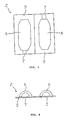
- the support member 2 as also shown in Figs. 2 to 4, is constituted by a molded plastic member obtained by vacuum molding of a plastic sheet, e.g. polypropylene sheet. It has a sheel structure comprising two shell halves 5, 5 formed integrally for opening and closing motions.
- Each shell half 5 is formed with a recess 6 (this reference numeral is affixed outside for convenience' sake in Figs. 1, 3 and 4) for charging the sealant therein.
- Each shell half 5 is further formed with a bendable portion 7 which is partially cut in so as to be bent when a connection of wires is sandwiched in between the shell halves 5, 5.
- the sealant 3 cures after it is filled into the support member 2 and is capable of retaining a gel-like tackiness to the extent of not flowing out from the interior of the support member 2.
- connection of wires using the splicing means 1 will now be described, in which there is used, for example, such a connection of wires as shown in Fig. 5.
- the illustrated connection is obtained by removing insulating coatings from three conductive wires W1-W3 to be connected together, thereby obtaining open wires, then contacting the open portion of the wire W1 with the open portions of the wires W2 and W3, and connecting them together using a metallic connecting terminal to obtain a Y-shaped connection 9.
- a curable silicone gel as the sealant 3 is formed within the support member 3 to obtain such splicing means 1 as shown in Fig. 1.
- connection 9 is embedded in the sealant in one shell half 5 of the support member 2 in an open condition of the shell halves 5, 5 of the coating unit 1, as shown in Fig. 6, then the shell halves 5, 5 are closed, whereby the connection 9 is embedded in the sealant 3 charged into the splicing means 1, as shown in Fig. 7.
- the shell halves 5, 5 are integrally fixed with retaining means 8, 8, e.g. staples, as shown in Fig. 8.
- the sealant 3 is pushed away in a amount corresponding to the volume of the connection 9 and moves in the arrowed directions in Fig. 9, getting into the gaps between the conductive wires in the connection 9 in an airtight manner,
- ultraviolet ray is radiated subsequently from the exterior of the splicing means 1 now holding the connection 9, using an ultraviolet ray irradiator, under conditions which permit an ultraviolet ray curable resin 3 in the support member 2 to be cured to seal the connection 9 of conductive wires positively. In this way the resin 3 in the support member 2 is cured to coat the connection 9.
- a formed hot-melt is used as the sealant 3
- a solid hot-melt is heat-melted, then gas is incorporated in the hot-melt under pressure, and the hot-melt with gas is discharged into auspport member 2 from a gun, whereby the gas foams and the hot-melt 3 thus foamed is charged into the support member 2.
- the hot-melt 3 cures to coat the connection 9.
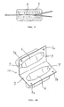
- Fig. 10 is a perspective view showing another example of a support member of the splicing means 1.
- This support member, indicated at 10 has, in addition to the same structure as that of the support member 2 described above, convexes 5a, 5a and concaves 5b, 5b in opposed positions of the surface of the shell halves 5, 5 so that when the shell halves 5, 5 are closed, the convexes 5a, 5a are fitted in the concaves 5b, 5b to effect locking into a closed state.
- Fig. 11 is a perspective view of a splicing means according to a second embodiment of the present Invention.
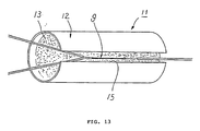
- This splicing means comprises a support member 12 and a sealant 13 filled into the support member 12.
- the support member 12 is constituted by a cylindrical body 14 both ends of which are open, with a slit 15 being formed longitudinally in a side portion of the cylindrical body 14 for fitting a connection of wires therein or for charging the sealant 13 therethrough.
- a side portion of the cylindrical body 14 may be cut a single line axially so that the slit 15 is formed by the expanding force of the cylindrical body 14.
- the shape of the slit 15 is not specially limited if only a connection of wires can be introduced into the support member 12 and the sealant 13 can be held within the support member.
- This method is suitable for splicing wires relatively small in diameter.
- Fig. 14 is a front view showing another example of a support member of the splicing means 11.
- This support member indicated at 17, comprises a cylindrical body 18 having a single cut-in portion formed axially thereof and a ring 19 fitted on the outer periphery of the cylindrical body 18 so as to be engaged with the cut ends of the cylindrical body, thereby expanding the cut ends to form a slit 15, as shown in Fig. 15.
- the cylindrical body 18 closes by virtue of its own restoring force to close the slit 15, as shown in Fig. 16. Therefore, by removing the ring 19 after a connection of wires is embedded in the sealant in the support member 17, the slit 15 is closed and the sealant is thereby held in the interior of the support member, so that the working efficiency is improved.
- the ring 19 may be attached to the tool side.
- Fig. 17 is a sectional view of a coating unit according to a third embodiment of the present invention.
- This splicing means comprises a support member 22 and a sealant 23 filled into the support member.
- the support member 22 is a U cup-shaped closed-end connector (hereinafter referred to simply as the "connector") made of a thermoplastic resin such as nylon.
- the connector used herein is defined by JIS-C-2807 (Closed-End Connector with Insulating Coating). In this connector, the dimensions of various portions shown in Fig. 18 are defined as follows: Symbol ... CE Designation ... 1 Dimensions: ⁇ D1 : 5.3 ⁇ D2 : 6.0 T : 0.8 L : 22.0 l2 : 6.0 l2 : 8.0 Pressure-bonding tool die symbol: 1 Designation ...
- this connection is a V-shaped connection 24, as shown in Fig. 19, obtained by removing insulating coatings of two wires W4 and W5 to be connected together, then contacting the resulting open portions of the conductive wires W4 and W5 with each other, followed by twisting and connecting together.
- the interior of the support member 22 is filled with the sealant 23 to form the splicing means 21, as shown in Fig. 17.
- connection 24 which is U-shaped, is embedded into the sealant 23 in the wire 22 which is the support member of the splicing means 21.
- the connector 22 is pressure-bonded from the outside using a pressure-bonding tool of any of the foregoing symbols conforming to the shape of the connector.
- the splicing means since the sealant having tackiness is filled into the support member, all that is required is only placing the connection of wires in the sealant followed by setting and fixing, whereby the splicing work is simplified and speed-up is attained. More particularly, in the splicing work for a connection of lead wires or the like, the splicing means of the present invention meets the recent demand for high working efficiency and speed-up in operations using robots, although the functions required somewhat differ depending on the use, etc. of wires.
- connections capable of being spliced with the splicing means of the present invention there are mentioned connections of wires such as electric wires and lead wires, connection of wire harnesses in automobiles, connections of conductive wires with a control board for electric equipment, connections of cables in plants, etc., connections of optical fiber cables, and connections of pipes.
- the support member as a constituent of the splicing means of the present invention is not limited to any of those described in the above embodiments.
- the support member has a structure capable of holding the sealant in the interior thereof, preventing drop-out of a connection of conductive wires inserted therein, and easily passing through a narrow space or a hole.
- Such a splicing means as shown in Fig. 1 was formed by filling the interior of a support member with silicone gel. The following methods were adopted for the formation of the support member, cured silicone gel, and splicing means.
- Example 2 Using the following components A and B and proportions (1) in Example 1 and (2) in Example 2, the components A and B in each Example were mixed together homogeneously with stirring and defoamed, then about 1.5 g of the resulting mixed resin was filled into the recesses 6 of the shell halves 5, 5, and held at 80°C ⁇ 1°C for 40 minutes, thereby allowed to cure, to obtain a cured silicone gel 3. In this way there was formed a splicing means 1. The cured silicone gel 3 was obtained also when the mixed resin was held at 25°C ⁇ 1°C for 24 hours,
- connection of wires was embedded in each of the splicing means 1 obtained in the above Examples 1 and 2.
- connection there was used a connection of conductive wires (trade name: TR-64 x 10, a product of Shinagawa Densen K.K.) connected together.
- TR-64 x 10 a product of Shinagawa Densen K.K.
- a polyvinyl chloride coating layer on the tip end portion of each of two such conductive wires was cut out about 100 mm and then the resulting open wire portions were bonded together by soldering or by electric heat welding to obtain such a Y-shaped connection 9 a shown in Fig. 9.
- connection 9 was embedded in the cured silicone gel 3 charge din one shell half 5 of the support member 2 of the coating unit 1, then the other shell half 5 serving as a lid of the support member 2 is closed, allowing the Y-shaped connection 9 to be embedded in the cured silicone gel 3, whereby the cured silicone gel 3 is pushed away in an amount corresponding to the volume of the connection 9, moves in the arrowed directions in Fig. 9 and gets into gaps formed in the connection 9.
- the shell halves 5, 5 of the support member 2 were closed and fixed together at two points using two steel staples SL-10 to thereby ensure adhesion.
- connection of wires sealed by the splicing means 1 in Example 1 was subjected to the following evaluation test, the results of which are as set forth in Table 1.
- connection 9 The time required for splicing the connection 9 was measured.
- connection 9 At the time of embedding the connection 9 in the splicing means 1, five grains of Hishipearl type A (trade name of Asahi Glass Company, Limited) (2 mm in diameter), as spherical silica gel desiccant grains for packaging use, were fixed to the connection 9, then the shell half 5 serving as a lid of the support member 2 was closed, and the connection 9 was subjected to a coating treatment in the same manner as in Examples 1 and 2. In this way there were prepared selability test samples.
- Hishipearl type A trade name of Asahi Glass Company, Limited
- the interior of a support member was filled with silicone gel to from such a splicing means 11 as shown in Fig. 11.
- the support member, cured silicone gel and splicing means were prepared in the following manner.
- Example 4 Using the following components A and B and proportions (3) in Example 3 and (4) in Example 4, the components A and B in each Example were mixed together homogeneously with stirring and defoamed, then about 1.5 g of the resulting mixed resin was poured into a cylindrical body 14 formed by sealing one opening end of a polypropylene tube (a product of Yamaichi Kako K.K.), and held at 80°C ⁇ 1°C for 40 minutes, thereby allowed to cure, to obtain a cured silicone gel 13. The cylindrical body 14 with the silicone gel 13 cured therein was cut into the length of 4 cm, and a single cut was made axially in a side part of the cylindrical body after the cutting to obtain a support member 12 having a slit 15. In this way there were formed splicing means 11.
- a polypropylene tube a product of Yamaichi Kako K.K.
- a Y-shaped connection 9 similar to that used in Example 1 was pushed through the slit 15 into the cured silicone gel charged in the support member 12 in the splicing means 11 to coat the connection 9.
- connection 9 coated with the coating units 11 obtained in Examples 3 and 4 were subjected to the same evaluation test as in Example 1, the results of which are as set forth in Table 2.
- Such a splicing means 21 as shown in Fig. 27 was formed by filling the interior of a support member with silicone gel.
- the support member, cured silicone gel and splicing means were prepared in the following manner.
- Example 6 Using the following components A and B and proportions (5) in Example 5 and (6) in Example 6, the components A and B in each Example 6 were mixed together homogeneously with stirring and defoamed, then about 1.5 g of the resulting mixed resin was charged into the support member 22 and held at 80°C ⁇ 1°C for 40 minutes, thereby allowed to cure, to obtain a cured silicone gel 23. In this way there were formed splicing means 21.
- connection there was used a connection of conductive wires (trade name: TR-64 x 10, a product of Shinagawa Densen K.K.) connected together.
- TR-64 x 10 a product of Shinagawa Densen K.K.
- a polyvinyl chloride coating layer on the tip end portion of each of two such wires was cut out about 10 mm and then the resulting open wire portions were bonded together by soldering or by electric heat welding to obtain such a V-shaped connection 24 as shown in Fig. 19.
- connection 24 was pushed into the cured silicone gel 23 in the connector 22 as the support member of each coating unit 21, as shown in Fig. 20. After it was confirmed that the connection 24 was located within the connector 22 and that the insulating coating portion of each of the two conductive wires was coated with the cured silicone gel 23, the connector 22 was compression-bonded from the outside using a compression-bonding tool conforming to the shape of the connector 22.
- the connector 24 coated with the splicing means 21 obtained in Examples 5 and 6 were subjected to the same evaluation test as in Example 1, provided the number of the silica gel desiccant grains was 2 to 3, the results of which are as set forth in Table 3.
- Table 3 Example 5 6 Workability 1-2 sec 1-2 sec Sealability good good
- a splicing means was formed by filling the interior of a support member with an ultraviolet-ray curable resin composition.
- the support member and the ultraviolet-ray curable resin composition were prepared by the following methods.
- Example 2 The same support member as that used in Example 1 was used. As polypropylene there was used one with no ultraviolet-ray absorber incorporated therein.
- an ultraviolet-ray curable resin composition using the following components and proportions: Bisphenol A type epoxy resin (trade name: Cylacure UVR-6405, a product of U.C.C. Co.) 60 parts by weight Alicyclic epoxy resin (trade name: Cylacure UVI-6110, a product of U.C.C. Co.) 40 parts by weight Allyl sulfonium salt (trade name: Cylacure UVI-6974 a product of U.C.C.
- Siloxane compound (trade name: KBM 703, a product of The Shin-etsu Chemical Industry Co., Ltd.) 4 parts by weight Benzsorbitol derivative (trade name: Gelol D, a product of Shin Nippon Rika) 1.5 parts by weight
- the ultraviolet-ray curable resin composition was obtained by mixing the above components in the proportions homogeneously with stirring.
- the ultraviolet-ray curable resin composition 3 was charged into the recess 6 of each shell half 5 of the support member 2 at 90-100°C and was allowed to stand until the temperature dropped to room temperature, wherey it was jellied to form a splicing means 1.
- the ultraviolet-ray curable resin composition may be forcibly cooled into jelly.
- connection of wires was embedded as follows in the splicing means 1 obtained above.
- connection there was used a connection of conductive wires (trade name: TR-64 x 10, a product of Shinagawa Densen K.K.) connected together.
- TR-64 x 10 a product of Shinagawa Densen K.K.
- a polyvinyl chloride coating layer on the tip end portion of each of two such wires was cut out about 10 mm and the resulting open wire portions were bonded together by soldering or by electric heat welding to obtian such a Y-shaped connection 9 as shown in Fig. 5.
- the Y-shaped connection 9 was embedded in the jellied, ultraviolet-ray curable resin composition 3 charged in one shell half 5 of the support member 2 of the splicing means 1. Thereafter, the other shell half 5 serving as a lid portion of the support member 2 was closed, allowing the Y-shaped connection 9 to be embedded in the jellied, ultraviolet-ray curable resin composition 3, whereby the resin composition was pushed away in an amount corresponding to the volume of the connection 9 and moves in the arrowed directions in Fig. 9, getting into gaps formed in the connection 9.
- ultraviolet ray was radiated to the splicing means 1 holding the connection 9 therein, using an ultraviolet ray irradiator (DHD-500CM, a product of Ork K.K.), under the irradiation conditions shown in Table 4, to thereby cure the ultraviolet-ray curable resin composition 3 charged in the support member 2 of the splicing means 1.
- DHD-500CM a product of Ork K.K.
- An ultraviolet-ray curable acrylic resin (TB 3042C, a product of Three Bond Co.) was mixed with a fine silica powder (Aerogil R-972, a product of Nippon Aerogil K.K.) as a gelling agent, at a resin/gelling agent ratio of 85/15, to obtain a jellied, ultraviolet-ray curable resin composition.
- Example 7 the same Y-shaped connection as in Example 7 was embedded in the above jellied, ultraviolet-ray curable resin composition 3 charged in the support member 2 of the splicing means 1. Thereafter, the two shell halves 5, 5 of the support member 2 were fixed and then ultraviolet-ray was radiated to the splicing means 1 holding the connection 9 therein under the irradiation conditions set out in Table 4 to cure the ultraviolet-ray curable resin composition 3 in the support member 2.
- connection 9 thus sealed by the coating unit 1 was subjected to the evaluation test, the results of which are as set forth in Table 4.
- a support member 2 and an ultraviolet-ray curable resin composition 3 were prepared in the same way as in Example 7.
- the resin composition 3 was charged into the recess 6 of each shell half 5 of the support member 2.
- the Y-shaped connection 9 was embedded in the jellied, ultraviolet-ray curable resin composition 3 in one shell half 5 of the support member 2. Then, before closing the other shell half 5 serving as a lid portion of the support member 2, ultraviolet ray was pre-radiated to the surface of the resin composition 3, and thereafter the shell half serving as a lid portion of the support member 2 was closed.
- This pre-radiation of the ultraviolet ray is performed for the following reason.
- a dark reaction involving dissociation of a catalyst once irradiated with light proceeds gradually in a dark place, so it is intended that the reaction of the ultraviolet-ray curable resin composition be allowed to proceed sufficiently in a shadow portion or in the interior by the radiation of light after closing of the shell half 5 which serves as a lid portion of the support member 2.
- the coating unit 1 now holding the connection 9 was irradiated with ultraviolet light using an ultraviolet ray irradiator (DHD-500CM, a product of Ork K.K.) under the irradiation conditions set out in Table 4 to cure the ultraviolet-ray curable resin composition 3 in the support member 2 of the splicing means 1.
- an ultraviolet ray irradiator DHD-500CM, a product of Ork K.K.
- Example 7 9 Conditions for Ultraviolet Ray Irradiation Preliminary Irradiation - - 41.8mV/cm2 1 sec Regular Irradiation 112mV/cm2 8 sec ditto ditto Workability 1-2 sec ditto 14-20 sec Mechanical Strength 9.6 kgf ditto 9.2 kgf Sealability good good good
- a coating nit for a connection of wires was formed by filling the interior of a support member with a foamed hot-melt.
- the support member, hot melt, application method, and the connection of wires used, are as follows.
- sealant 3 there was sued an ethylene vinyl acetate polymer (trade name: TBX-36-122, a product of Three Bond Co.).
- a foamed hot melt applicator (FM 151, a product of NORDSON INC., U.S.A.), nitrogen gas was mixed into the hot-melt and then the hot-melt with gas was charged about 1.6 to 1.7 cc into the recess 6 of each shell half 5 of the support member 2 at a temperature of 130°C and a foaming ratio of 1.5X to form a splicing means 1.
- FM 151 a product of NORDSON INC., U.S.A.
- connection there was used a connection of the same wires (TR-64 x 10, a product of Shinagawa Densen K.K.) as those used in Example 7. Insulating layers of polyvinyl chloride on the tip end portions of two such wires were cut out about 10 mm and the resulting open wire portions were bonded together by soldering or by electric heat welding to form such Y-shaped connection 9 as shown in Fig. 5.
- the Y-shaped connection 9 was embedded into the foamed hot-melt 3 charged in one shell half 5 of the support member 2 and then the other shell half 5 serving as a lid portion of the support member 2 was closed, allowing the hot-melt agent to get into gaps formed in the connection 9.
- the coating unit of the present invention for splicing electric wires for example it becomes possible to perform the sealing and coating operation quickly in the means of second and so the workability is improved.
- the coating unit of the invention is superior in airtightness, capable of coming into close contact with a connection of conductive wires, and has improved sealability which permits complete waterproofing and protection of the connection of conductive wires.
- the splicing means of the invention is applied to a connection of wires which constitute a wire harness, the extended distance of the conductors is reduced, whereby the reduction of weight and effective utilization of space can be attained.
- a jellied ultraviolet-ray curable resin is used as the sealant, it is employable even in a high temperature atmosphere of 120°C or so, and open time is long; besides, the resin does not flow out even when charged into the support member, thus resulting in improvement of the working efficiency.
Landscapes
- Cable Accessories (AREA)
- Connector Housings Or Holding Contact Members (AREA)
- Sealing Material Composition (AREA)
Applications Claiming Priority (2)
| Application Number | Priority Date | Filing Date | Title |
|---|---|---|---|
| JP187070/89 | 1989-07-19 | ||
| JP1187070A JPH0353466A (ja) | 1989-07-19 | 1989-07-19 | 連結部材の被覆材 |
Publications (2)
| Publication Number | Publication Date |
|---|---|
| EP0409444A2 true EP0409444A2 (de) | 1991-01-23 |
| EP0409444A3 EP0409444A3 (en) | 1992-01-29 |
Family
ID=16199611
Family Applications (1)
| Application Number | Title | Priority Date | Filing Date |
|---|---|---|---|
| EP19900307262 Withdrawn EP0409444A3 (en) | 1989-07-19 | 1990-07-03 | Means for splicing wires |
Country Status (3)
| Country | Link |
|---|---|
| US (1) | US5099088A (de) |
| EP (1) | EP0409444A3 (de) |
| JP (1) | JPH0353466A (de) |
Cited By (12)
| Publication number | Priority date | Publication date | Assignee | Title |
|---|---|---|---|---|
| WO1995011543A1 (en) * | 1993-10-18 | 1995-04-27 | Raychem Corporation | Closure for high voltage cable connections |
| US6246003B1 (en) | 1995-07-28 | 2001-06-12 | Ian Ferris | Sealing enclosure device |
| WO2001082435A3 (en) * | 2000-04-24 | 2002-02-28 | Tyco Electronics Corp | Wrap-around cable sleeves having an expandable body portion and methods of making same |
| US6706968B2 (en) | 2000-04-24 | 2004-03-16 | Tyco Electronics Corporation | Environmentally sealed wrap-around sleeves having a longitudinal sealant chamber |
| US7141738B2 (en) | 2004-02-02 | 2006-11-28 | 3M Innovative Properties Company | Re-enterable splice enclosure |
| US7214735B2 (en) | 2004-02-02 | 2007-05-08 | 3M Innovative Properties Company | Microsphere-filled sealant materials |
| WO2010059615A3 (en) * | 2008-11-18 | 2011-09-29 | Tyco Electronics Corporation | Sealant-filled enclosures and methods for environmentally protecting a connection |
| US8415564B2 (en) | 2009-11-04 | 2013-04-09 | Tyco Electronics Corporation | Wrap-around cable sleeve assemblies and methods for making and using the same |
| CN102388516B (zh) * | 2008-11-18 | 2014-10-29 | 泰科电子有限公司 | 用于对接头进行环境保护的密封剂填充式封罩和方法 |
| US10840615B2 (en) | 2018-06-28 | 2020-11-17 | Te Connectivity Corporation | Connection enclosure assemblies, connector systems and methods for forming an enclosed connection between conductors |
| US11431114B2 (en) | 2020-02-14 | 2022-08-30 | Te Connectivity Solutions Gmbh | Enclosed connection systems for forming an enclosed connection between conductors, and methods including same |
| EP4483462A4 (de) * | 2022-02-21 | 2026-02-25 | Commscope Technologies Llc | Kabelabdichtungsanordnung für ein gehäuse |
Families Citing this family (81)
| Publication number | Priority date | Publication date | Assignee | Title |
|---|---|---|---|---|
| US5111001A (en) * | 1990-04-13 | 1992-05-05 | Raychem Corporation | Splice case |
| EP0506404B1 (de) * | 1991-03-26 | 1996-06-05 | Canon Kabushiki Kaisha | Verfahren zum Herstellen von Formteilen aus Kunststoff mit Reliefmustern auf der Oberfläche |
| US5783776A (en) * | 1991-10-29 | 1998-07-21 | O-Z Gedney Company Llc | Electrical cable penetration seal with compliant module |
| US5416271A (en) * | 1991-10-29 | 1995-05-16 | General Signal Corporation | Electrical cable penetration seal with compliant module |
| US5318069A (en) * | 1992-01-17 | 1994-06-07 | Stant Manufacturing Inc. | Tank venting and vapor recovery system |
| US5399810A (en) * | 1992-11-03 | 1995-03-21 | Three Bond Co., Ltd. | Means for coating connecting portions of electrical wires |
| US5679927A (en) * | 1993-05-13 | 1997-10-21 | Communications Technology Corporation | Buried service wire closure |
| US5387763A (en) * | 1993-05-13 | 1995-02-07 | Communications Technology Corporation | Enclosure for straight cable splice |
| JP2894581B2 (ja) * | 1993-05-24 | 1999-05-24 | 矢崎総業株式会社 | ワイヤーハーネスの防水構造 |
| US5397859A (en) * | 1993-12-10 | 1995-03-14 | The Whitaker Corporation | Enclosure with sealant for spliced coaxial cables |
| JP3004630U (ja) * | 1994-05-25 | 1994-11-22 | 旭電機株式会社 | 絶縁ケーブル分岐接続の絶縁処理構造 |
| KR19980703658A (ko) * | 1995-04-12 | 1998-12-05 | 드로즈프랑소와 | 콤팩트 트랜스폰더 및 그 제조방법 |
| US5763835A (en) * | 1995-11-01 | 1998-06-09 | Raychem Corporation | Gel-filled closure |
| US5844171A (en) * | 1997-04-22 | 1998-12-01 | Mev Corporation | Environmentally enclosed cable splice |
| US6294737B1 (en) | 1999-06-23 | 2001-09-25 | P. L. Chestney | Reusable closure for wire splices |
| US6478606B1 (en) * | 2000-01-11 | 2002-11-12 | Mcnerney Gerald | Twist-on connector with a heat-shrinkable skirt |
| US6730847B1 (en) | 2000-03-31 | 2004-05-04 | Tyco Electronics Corporation | Electrical connection protector kit and method for using the same |
| US6627818B2 (en) | 2000-10-02 | 2003-09-30 | Tyco Electronics Corporation | Electrical connection protector kit and method for using the same |
| US6908682B2 (en) * | 2002-09-12 | 2005-06-21 | 3M Innovative Properties Company | Photocured silicone sealant having improved adhesion to plastic |
| US6854996B2 (en) * | 2002-12-20 | 2005-02-15 | Tyco Electronics Corporation | Electrical connectors and methods for using the same |
| US7056151B2 (en) * | 2003-02-18 | 2006-06-06 | Homac Mfg. Company | Connector and insulating boot for different sized conductors and associated methods |
| US7120347B2 (en) * | 2004-01-27 | 2006-10-10 | Corning Cable Systems Llc | Multi-port optical connection terminal |
| US7013074B2 (en) * | 2004-02-06 | 2006-03-14 | Corning Cable Systems Llc | Optical connection closure having at least one connector port |
| US7094972B2 (en) * | 2004-07-13 | 2006-08-22 | Thomas & Betts International, Inc. | Insulating cover for electrical connectors |
| US7680388B2 (en) | 2004-11-03 | 2010-03-16 | Adc Telecommunications, Inc. | Methods for configuring and testing fiber drop terminals |
| US7489849B2 (en) | 2004-11-03 | 2009-02-10 | Adc Telecommunications, Inc. | Fiber drop terminal |
| US20060153516A1 (en) * | 2005-01-13 | 2006-07-13 | Napiorkowski John J | Network interface device having integral slack storage compartment |
| AU2006236409B2 (en) | 2005-04-19 | 2011-05-19 | Adc Telecommunications, Inc. | Loop back plug and method |
| US7273984B2 (en) * | 2005-07-11 | 2007-09-25 | Twins Investments Company | Outdoor cord connection cover apparatus |
| US7378593B2 (en) * | 2005-07-26 | 2008-05-27 | Tyco Electronics Corporation | Electrical connection protector kits, insert assemblies and methods for using the same |
| US7109423B1 (en) | 2005-07-26 | 2006-09-19 | Tyco Electronics Corporation | Electrical connection protector kits, insert assemblies and methods for using the same |
| US7418177B2 (en) | 2005-11-10 | 2008-08-26 | Adc Telecommunications, Inc. | Fiber optic cable breakout system, packaging arrangement, and method of installation |
| US7201596B1 (en) | 2006-01-06 | 2007-04-10 | Tyco Electronics Corporation | Electrical connector systems, plug systems and methods for using the same |
| US7424189B2 (en) * | 2006-03-09 | 2008-09-09 | Adc Telecommunications, Inc. | Mid-span breakout with potted closure |
| US7251411B1 (en) | 2006-03-09 | 2007-07-31 | Adc Telecommunication, Inc. | Fiber optic cable breakout configuration with “Y” block |
| US7317863B2 (en) * | 2006-03-09 | 2008-01-08 | Adc Telecommunications, Inc. | Fiber optic cable breakout configuration with retention block |
| US7422378B2 (en) | 2006-03-09 | 2008-09-09 | Adc Telecommunications, Inc. | Fiber optic cable breakout configuration with excess fiber length |
| US7590321B2 (en) * | 2006-03-09 | 2009-09-15 | Adc Telecommunications, Inc. | Mid-span breakout with helical fiber routing |
| US7599598B2 (en) * | 2006-08-09 | 2009-10-06 | Adc Telecommunications, Inc. | Cable payout systems and methods |
| US7840109B2 (en) * | 2006-08-14 | 2010-11-23 | Adc Telecommunications, Inc. | Factory spliced cable assembly |
| WO2008021253A2 (en) * | 2006-08-14 | 2008-02-21 | Adc Telecommunications, Inc. | Factory spliced cable assembly |
| US7289714B1 (en) | 2006-09-26 | 2007-10-30 | Adc Telecommunication, Inc. | Tubing wrap procedure |
| US7480436B2 (en) * | 2006-10-10 | 2009-01-20 | Adc Telecommunications, Inc. | Systems and methods for securing a tether to a distribution cable |
| US7403685B2 (en) * | 2006-10-13 | 2008-07-22 | Adc Telecommunications, Inc. | Overmold zip strip |
| US7489843B2 (en) * | 2007-02-06 | 2009-02-10 | Adc Telecommunications, Inc. | Polyurethane to polyethylene adhesion process |
| US7558458B2 (en) * | 2007-03-08 | 2009-07-07 | Adc Telecommunications, Inc. | Universal bracket for mounting a drop terminal |
| US7736187B2 (en) * | 2007-03-20 | 2010-06-15 | Tyco Electronics Corporation | Electrical connector assemblies and joint assemblies and methods for using the same |
| US7453042B2 (en) * | 2007-04-09 | 2008-11-18 | Andrew Llc | Cable and apparatus interconnection close quarters environmental seal |
| US7532799B2 (en) * | 2007-04-12 | 2009-05-12 | Adc Telecommunications | Fiber optic telecommunications cable assembly |
| US7609925B2 (en) * | 2007-04-12 | 2009-10-27 | Adc Telecommunications, Inc. | Fiber optic cable breakout configuration with tensile reinforcement |
| JP2008311183A (ja) * | 2007-06-18 | 2008-12-25 | Mitsubishi Electric Corp | ワイヤーハーネス |
| US7736165B2 (en) * | 2007-07-16 | 2010-06-15 | Tyco Electronics Corporation | Electrical connector assemblies and methods for forming and using the same |
| US7769261B2 (en) * | 2007-09-05 | 2010-08-03 | Adc Telecommunications, Inc. | Fiber optic distribution cable |
| US7740409B2 (en) * | 2007-09-19 | 2010-06-22 | Corning Cable Systems Llc | Multi-port optical connection terminal |
| JP2009217982A (ja) * | 2008-03-07 | 2009-09-24 | Fujikura Ltd | 分岐接続部の絶縁カバー |
| USD613697S1 (en) * | 2008-10-22 | 2010-04-13 | Blue Lounge Design, Llc | Container with lid for storing power cords and cables for electronic devices |
| WO2010059613A2 (en) * | 2008-11-18 | 2010-05-27 | Tyco Electronics Corporation | Sealant-filled enclosures and methods for environmentally protecting a connection |
| USD607412S1 (en) | 2009-05-21 | 2010-01-05 | William Palomaki | Plug cover lock |
| US8604342B2 (en) * | 2009-07-14 | 2013-12-10 | Shoals Technologies Group, Llc | Low leakage electrical joints and wire harnesses, and method of making the same |
| US8915659B2 (en) | 2010-05-14 | 2014-12-23 | Adc Telecommunications, Inc. | Splice enclosure arrangement for fiber optic cables |
| US8431824B1 (en) * | 2010-09-01 | 2013-04-30 | The Patent Store Llc | Direct bury splice kits |
| CN103221863B (zh) | 2010-10-28 | 2016-06-01 | 康宁光缆系统有限责任公司 | 抗冲击光纤外壳及相关方法 |
| US8885998B2 (en) | 2010-12-09 | 2014-11-11 | Adc Telecommunications, Inc. | Splice enclosure arrangement for fiber optic cables |
| CA141533S (en) * | 2011-02-04 | 2012-02-21 | Line Europ Ltd D | Cable tidy |
| US8408929B2 (en) * | 2011-03-28 | 2013-04-02 | Shoals Technologies Group, Llc | Guard for connection point of adjoined wire connectors |
| US20120261156A1 (en) * | 2011-04-12 | 2012-10-18 | 3M Innovative Properties Company | Protection device for a cable connection |
| US9069151B2 (en) | 2011-10-26 | 2015-06-30 | Corning Cable Systems Llc | Composite cable breakout assembly |
| US9059580B2 (en) | 2011-11-10 | 2015-06-16 | Thomas & Betts International, Llc | Curing system for sealing an electrical fitting |
| US8962998B2 (en) | 2012-02-08 | 2015-02-24 | Shoals Technologies Group, Llc | Solar panel junction box capable of integrating with a variety of accessory modules, and method of use |
| US8873926B2 (en) | 2012-04-26 | 2014-10-28 | Corning Cable Systems Llc | Fiber optic enclosures employing clamping assemblies for strain relief of cables, and related assemblies and methods |
| DE102013013366A1 (de) * | 2013-08-13 | 2014-08-14 | Lisa Dräxlmaier GmbH | Verfahren und Vorrichtung zur isolierenden Versiegelung von Leitungen |
| DE102013217177B4 (de) * | 2013-08-28 | 2016-08-25 | Volkswagen Aktiengesellschaft | Verfahren zur elektrischen Isolation eines Splices |
| US10316152B2 (en) | 2014-01-10 | 2019-06-11 | CommScope Connectivity Belgium BVBA | Thermoplastic gel compositions and their methods of making |
| JP6439743B2 (ja) * | 2016-04-27 | 2018-12-19 | 株式会社オートネットワーク技術研究所 | ワイヤーハーネス |
| JP6439742B2 (ja) * | 2016-04-27 | 2018-12-19 | 株式会社オートネットワーク技術研究所 | ワイヤーハーネス |
| US10299392B2 (en) * | 2017-10-12 | 2019-05-21 | Goodrich Corporation | Integrally bonded and installed protective enclosure |
| JP6498742B1 (ja) * | 2017-11-24 | 2019-04-10 | 京セラ株式会社 | 保護部品及び保護方法 |
| JP6791923B2 (ja) | 2018-09-20 | 2020-11-25 | ファナック株式会社 | 加工システムおよび加工方法 |
| JP7390132B2 (ja) * | 2019-08-21 | 2023-12-01 | 株式会社オートネットワーク技術研究所 | ワイヤーハーネス |
| DE102020200548A1 (de) | 2020-01-17 | 2021-07-22 | Friedrich-Alexander-Universität Erlangen-Nürnberg | Verfahren zu der Herstellung eines Kabelbaums sowie Vorrichtung zum Aufbringen einer Umhüllung auf einen verzweigten Leitungsstrang |
| US20220301746A1 (en) * | 2021-03-18 | 2022-09-22 | Schluter Systems L.P. | Cold Lead Termination Method |
Family Cites Families (18)
| Publication number | Priority date | Publication date | Assignee | Title |
|---|---|---|---|---|
| US3020260A (en) * | 1960-08-18 | 1962-02-06 | Dow Corning | Organosiloxane potting compound |
| FR2088865A5 (de) * | 1970-04-28 | 1972-01-07 | Minnesota Mining Mfg France | |
| DE2129342C3 (de) * | 1971-06-12 | 1975-02-13 | John Thomas Los Angeles Thompson | Kapseleinrichtung zur Aufnahme von SpleiBverbindungen elektrischer Leiter |
| US3879575A (en) * | 1974-02-21 | 1975-04-22 | Bell Telephone Labor Inc | Encapsulating compound and closure |
| FR2322312A1 (fr) * | 1975-08-27 | 1977-03-25 | Raychem Corp | Procede de preparation d'un ensemble a joint hermetique |
| DE3035183A1 (de) * | 1980-09-18 | 1982-04-22 | Köttgen GmbH & Co KG, 5060 Bergisch Gladbach | Mit vergussmasse auffuellbarer muffenkoerper fuer stromkabel |
| DE3211067A1 (de) * | 1982-03-25 | 1983-09-29 | Siemens AG, 1000 Berlin und 8000 München | Schaeumbarer schmelzkleber |
| US4550220A (en) * | 1983-11-04 | 1985-10-29 | National Industries, Inc. | Splice insulator assembly |
| US4701574A (en) * | 1985-02-06 | 1987-10-20 | Raychem Corp. | Cable sealing apparatus |
| US4721832A (en) * | 1985-05-02 | 1988-01-26 | Raychem Corporation | Electrical connection sealing device |
| US4647717A (en) * | 1985-05-02 | 1987-03-03 | Raychem Corp. | Gel filled container |
| GB8515009D0 (en) * | 1985-06-13 | 1985-07-17 | Raychem Sa Nv | Protection of terminal blocks |
| US4751350A (en) * | 1986-11-06 | 1988-06-14 | Raychem Corporation | Sealing device and retention member therefor |
| US4888070A (en) * | 1987-12-01 | 1989-12-19 | Raychem Corporation | Environmental sealing of a substrate |
| JPH01154472A (ja) * | 1987-12-09 | 1989-06-16 | Three Bond Co Ltd | 接合線材の接続装置 |
| US4849580A (en) * | 1988-02-11 | 1989-07-18 | Minnesota Mining And Manufacturing Company | Environmental protection closure for wire splices; and method |
| US4859809A (en) * | 1988-04-27 | 1989-08-22 | Raychem Corporation | Splice case |
| US4943685A (en) * | 1989-03-17 | 1990-07-24 | Commu-Tec, Inc. | Cable splicing and termination system |
-
1989
- 1989-07-19 JP JP1187070A patent/JPH0353466A/ja active Pending
-
1990
- 1990-06-07 US US07/534,727 patent/US5099088A/en not_active Expired - Fee Related
- 1990-07-03 EP EP19900307262 patent/EP0409444A3/en not_active Withdrawn
Cited By (19)
| Publication number | Priority date | Publication date | Assignee | Title |
|---|---|---|---|---|
| WO1995011543A1 (en) * | 1993-10-18 | 1995-04-27 | Raychem Corporation | Closure for high voltage cable connections |
| US5606149A (en) * | 1993-10-18 | 1997-02-25 | Raychem Corporation | Closure for high voltage cable connections having an insulating gel to form gel to gel interface with other insulating gel |
| US6246003B1 (en) | 1995-07-28 | 2001-06-12 | Ian Ferris | Sealing enclosure device |
| KR100885333B1 (ko) * | 2000-04-24 | 2009-02-26 | 타이코 일렉트로닉스 코포레이션 | 연장가능한 바디부를 가진 랩 어라운드 케이블 슬리브 및이의 제조 방법 |
| US6545219B1 (en) | 2000-04-24 | 2003-04-08 | Tyco Electronics Corporation | Wrap-around cable sleeves having an expandable body portion and methods of making same |
| US6706968B2 (en) | 2000-04-24 | 2004-03-16 | Tyco Electronics Corporation | Environmentally sealed wrap-around sleeves having a longitudinal sealant chamber |
| WO2001082435A3 (en) * | 2000-04-24 | 2002-02-28 | Tyco Electronics Corp | Wrap-around cable sleeves having an expandable body portion and methods of making same |
| US7141738B2 (en) | 2004-02-02 | 2006-11-28 | 3M Innovative Properties Company | Re-enterable splice enclosure |
| US7214735B2 (en) | 2004-02-02 | 2007-05-08 | 3M Innovative Properties Company | Microsphere-filled sealant materials |
| US8227696B2 (en) | 2008-11-18 | 2012-07-24 | Tyco Electronics Corporation | Sealant-filled enclosures and methods for environmentally protecting a connection |
| WO2010059615A3 (en) * | 2008-11-18 | 2011-09-29 | Tyco Electronics Corporation | Sealant-filled enclosures and methods for environmentally protecting a connection |
| CN102388516B (zh) * | 2008-11-18 | 2014-10-29 | 泰科电子有限公司 | 用于对接头进行环境保护的密封剂填充式封罩和方法 |
| US9059579B2 (en) | 2008-11-18 | 2015-06-16 | Tyco Electronics Corporation | Sealant-filled enclosures and methods for environmentally protecting a connection |
| CN102498627B (zh) * | 2008-11-18 | 2015-09-30 | 泰科电子有限公司 | 用于对接头进行环境保护的密封剂填充式封罩和方法 |
| US8415564B2 (en) | 2009-11-04 | 2013-04-09 | Tyco Electronics Corporation | Wrap-around cable sleeve assemblies and methods for making and using the same |
| US10840615B2 (en) | 2018-06-28 | 2020-11-17 | Te Connectivity Corporation | Connection enclosure assemblies, connector systems and methods for forming an enclosed connection between conductors |
| US11121480B2 (en) | 2018-06-28 | 2021-09-14 | Te Connectivity Corporation | Connection enclosure assemblies, connector systems and methods for forming an enclosed connection between conductors |
| US11431114B2 (en) | 2020-02-14 | 2022-08-30 | Te Connectivity Solutions Gmbh | Enclosed connection systems for forming an enclosed connection between conductors, and methods including same |
| EP4483462A4 (de) * | 2022-02-21 | 2026-02-25 | Commscope Technologies Llc | Kabelabdichtungsanordnung für ein gehäuse |
Also Published As
| Publication number | Publication date |
|---|---|
| JPH0353466A (ja) | 1991-03-07 |
| EP0409444A3 (en) | 1992-01-29 |
| US5099088A (en) | 1992-03-24 |
Similar Documents
| Publication | Publication Date | Title |
|---|---|---|
| US5099088A (en) | Means for splicing wires | |
| US4477376A (en) | Castable mixture for insulating spliced high voltage cable | |
| US20080283268A1 (en) | Method for Stopping Water of Earth Wire and Earth Wire | |
| US4354053A (en) | Spliced high voltage cable | |
| JP4297293B2 (ja) | 端子付自動車ハーネス | |
| CN109074914A (zh) | 线束 | |
| JP4646260B2 (ja) | 端子付自動車ハーネス | |
| CN112204835A (zh) | 用于密封海底电缆段的切断端部的方法 | |
| JPH11510303A (ja) | 囲い込み密閉装置 | |
| CA1321695C (en) | Method for sealing a cable bundle in longitudinal direction | |
| JP3411366B2 (ja) | ワイヤハーネス枝線分岐部の防水処理方法及びその加工装置 | |
| US5952071A (en) | Curable adhesive system | |
| CN1037300A (zh) | 包绕受热复原的密封制品 | |
| JPH01154473A (ja) | 連結部材の被覆材 | |
| JP2015174995A (ja) | 粘着剤組成物、防食端子及び端子付き被覆電線 | |
| CN1198896C (zh) | 包覆的不连续处和对不连续处进行密封的方法 | |
| JP4805074B2 (ja) | 端子付自動車ハーネスの製造方法 | |
| JP2002305065A (ja) | コネクタ端子挿入口と電線との間の封止方法および防水コネクタ | |
| JPH053054A (ja) | 被覆具 | |
| US4270021A (en) | High voltage cable splice using condensation reaction polymeric insulation | |
| US4226651A (en) | High voltage cable splicing - additive reaction | |
| JP2007317470A (ja) | 芯線接続部の封止方法 | |
| JP3622333B2 (ja) | グロメット充填用シール剤、該シール剤を用いたワイヤハーネスのシール方法およびシール構造 | |
| CA1178413A (en) | Dimensionally recoverable article | |
| JPH0447432B2 (de) |
Legal Events
| Date | Code | Title | Description |
|---|---|---|---|
| PUAI | Public reference made under article 153(3) epc to a published international application that has entered the european phase |
Free format text: ORIGINAL CODE: 0009012 |
|
| AK | Designated contracting states |
Kind code of ref document: A2 Designated state(s): DE FR GB |
|
| 17P | Request for examination filed |
Effective date: 19901221 |
|
| PUAL | Search report despatched |
Free format text: ORIGINAL CODE: 0009013 |
|
| AK | Designated contracting states |
Kind code of ref document: A3 Designated state(s): DE FR GB |
|
| STAA | Information on the status of an ep patent application or granted ep patent |
Free format text: STATUS: THE APPLICATION HAS BEEN WITHDRAWN |
|
| 18W | Application withdrawn |
Withdrawal date: 19920402 |
|
| R18W | Application withdrawn (corrected) |
Effective date: 19920402 |