EP0409471A2 - Dispositif pour la fabrication de blocs en béton - Google Patents
Dispositif pour la fabrication de blocs en béton Download PDFInfo
- Publication number
- EP0409471A2 EP0409471A2 EP90307564A EP90307564A EP0409471A2 EP 0409471 A2 EP0409471 A2 EP 0409471A2 EP 90307564 A EP90307564 A EP 90307564A EP 90307564 A EP90307564 A EP 90307564A EP 0409471 A2 EP0409471 A2 EP 0409471A2
- Authority
- EP
- European Patent Office
- Prior art keywords
- mould box
- vibration
- mould
- cavities
- feed
- Prior art date
- Legal status (The legal status is an assumption and is not a legal conclusion. Google has not performed a legal analysis and makes no representation as to the accuracy of the status listed.)
- Granted
Links
Images



Classifications
-
- B—PERFORMING OPERATIONS; TRANSPORTING
- B28—WORKING CEMENT, CLAY, OR STONE
- B28B—SHAPING CLAY OR OTHER CERAMIC COMPOSITIONS; SHAPING SLAG; SHAPING MIXTURES CONTAINING CEMENTITIOUS MATERIAL, e.g. PLASTER
- B28B3/00—Producing shaped articles from the material by using presses; Presses specially adapted therefor
-
- B—PERFORMING OPERATIONS; TRANSPORTING
- B28—WORKING CEMENT, CLAY, OR STONE
- B28B—SHAPING CLAY OR OTHER CERAMIC COMPOSITIONS; SHAPING SLAG; SHAPING MIXTURES CONTAINING CEMENTITIOUS MATERIAL, e.g. PLASTER
- B28B3/00—Producing shaped articles from the material by using presses; Presses specially adapted therefor
- B28B3/02—Producing shaped articles from the material by using presses; Presses specially adapted therefor wherein a ram exerts pressure on the material in a moulding space; Ram heads of special form
- B28B3/022—Producing shaped articles from the material by using presses; Presses specially adapted therefor wherein a ram exerts pressure on the material in a moulding space; Ram heads of special form combined with vibrating or jolting
-
- B—PERFORMING OPERATIONS; TRANSPORTING
- B28—WORKING CEMENT, CLAY, OR STONE
- B28B—SHAPING CLAY OR OTHER CERAMIC COMPOSITIONS; SHAPING SLAG; SHAPING MIXTURES CONTAINING CEMENTITIOUS MATERIAL, e.g. PLASTER
- B28B1/00—Producing shaped prefabricated articles from the material
- B28B1/08—Producing shaped prefabricated articles from the material by vibrating or jolting
- B28B1/087—Producing shaped prefabricated articles from the material by vibrating or jolting by means acting on the mould ; Fixation thereof to the mould
-
- B—PERFORMING OPERATIONS; TRANSPORTING
- B28—WORKING CEMENT, CLAY, OR STONE
- B28B—SHAPING CLAY OR OTHER CERAMIC COMPOSITIONS; SHAPING SLAG; SHAPING MIXTURES CONTAINING CEMENTITIOUS MATERIAL, e.g. PLASTER
- B28B13/00—Feeding the unshaped material to moulds or apparatus for producing shaped articles; Discharging shaped articles from such moulds or apparatus
- B28B13/02—Feeding the unshaped material to moulds or apparatus for producing shaped articles
- B28B13/0215—Feeding the moulding material in measured quantities from a container or silo
-
- B—PERFORMING OPERATIONS; TRANSPORTING
- B28—WORKING CEMENT, CLAY, OR STONE
- B28B—SHAPING CLAY OR OTHER CERAMIC COMPOSITIONS; SHAPING SLAG; SHAPING MIXTURES CONTAINING CEMENTITIOUS MATERIAL, e.g. PLASTER
- B28B13/00—Feeding the unshaped material to moulds or apparatus for producing shaped articles; Discharging shaped articles from such moulds or apparatus
- B28B13/02—Feeding the unshaped material to moulds or apparatus for producing shaped articles
- B28B13/0215—Feeding the moulding material in measured quantities from a container or silo
- B28B13/022—Feeding several successive layers, optionally of different materials
-
- B—PERFORMING OPERATIONS; TRANSPORTING
- B28—WORKING CEMENT, CLAY, OR STONE
- B28B—SHAPING CLAY OR OTHER CERAMIC COMPOSITIONS; SHAPING SLAG; SHAPING MIXTURES CONTAINING CEMENTITIOUS MATERIAL, e.g. PLASTER
- B28B3/00—Producing shaped articles from the material by using presses; Presses specially adapted therefor
- B28B3/02—Producing shaped articles from the material by using presses; Presses specially adapted therefor wherein a ram exerts pressure on the material in a moulding space; Ram heads of special form
- B28B3/04—Producing shaped articles from the material by using presses; Presses specially adapted therefor wherein a ram exerts pressure on the material in a moulding space; Ram heads of special form with one ram per mould
- B28B3/06—Producing shaped articles from the material by using presses; Presses specially adapted therefor wherein a ram exerts pressure on the material in a moulding space; Ram heads of special form with one ram per mould with two or more ram and mould sets
Definitions
- the present invention relates to machines for manufacturing concrete blocks.
- a particular problem resides in that the feed drawer will not distribute concrete material evenly into each of the cavities of the mould box. This is because as a feed drawer passes over a mould box, material which initially is displaced into the first cavities become more compacted than material which is displaced into downstream cavities. Then, when the feed drawer is retracted, it may leave an uneven profile of concrete material in the mould box, i.e. there may be more material at one end than at the other. Therefore, it becomes advantageous to provide some type of vibration which will ensure uniform distribution of the concrete material in the mould box, and it may be important to vibrate the concrete material during compression also.
- apparatus for continuously forming concrete blocks comprising a supporting frame, a mould box flexibly mounted on the frame and having internal cavities contoured to define preselected mould patterns, feed means for receiving concrete materials and operable for selectively positioning over an upper surface of the mould box, for investing concrete material into the cavities, vibration means mounted on said mould box for imparting vibration thereto and power driven means, selectively operable to impart vibration to said vibration means.
- the invention also provides a method for continuously forming concrete blocks comprising: providing a mould box having internal cavities contoured to define preselected block patterns; investing concrete material into the cavities; imparting vibration to the mould box during the investing step by vibrating selected portions of the mould box; compressing the concrete material within the mould box while continuing to impart vibration thereto; stopping the mould box vibration; and discharging the concrete material from the mould box after compression.
- controlled and selective vibration of a filled mould box at opposite ends thereof, can be achieved to ensure even distribution of concrete material, i.e. that each cavity in the mould box is filled with the same mass of material.
- First and second feed drawers may be mounted adjacent the frame and selectively operable for independent, rectilinear shifting from positions remote from the mould box to corresponding positions thereabove.
- a first feed drawer may be disposed over the mould box for investing material thereinto, and after retraction of that feed drawer, the other may be moved into position for investing different coloured concrete material on top of that already in the mould box.
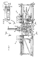
- the illustrated apparatus 10 is formed in sections comprising a first feed drawer assembly 12, a central block forming section 14 and a second feed drawer assembly 16, which is provided for optional capability of producing blocks or pavers having a colour "cap".
- Block forming section 14 is designed as a self-supporting unit symmetrical about its own centreline, and the first and second feed drawer assemblies also are individual and separate units which are mounted on power-driven wheels so that they may be rolled away for easy maintenance.
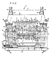
- the block forming section 14 includes a box-like frame 18, which includes interconnected upright members and cross-beams, etc. It will be noted that frame 18, which includes a base 20, is mounted on vibration isolators 22. As shown in Figure 2, block forming section 14 is provided with a pair of opposed, upstanding guide columns 24,26 which slidably receive a transversely-extending compression beam 28 and a main or stripper beam 30 disposed therebeneath, provided with bushings 32,34 and bushings 36,38 respectively. Compression beam 28 is provided with a plurality of downwardly extending shoes, such as indicated at 40-48 which are configured for compressing concrete material and ejecting the formed product from the cavities in a mould box in a manner to be described.
- Each of the shoes is provided with a base plate, such as indicated at 40a, 42a etc.
- Dashed line A shown adjacent top of Figure 2 represents the maximum extent to which compression beam 28 will be raised, and at that point, the positions of base plates, such as indicated at 40a, 42a etc are shown in dashed lines also.
- stripper beam 30 Mounted on opposite ends of stripper beam 30 are fluid-actuated cylinders 50 and 56 and associated piston rods 52,58 operable for vertically shifting compression beam 28 relative to the stripper beam. Air bags 54,56 provide vibration isolation and cushion the action of compression beam 28 and its associated components in operation. Additional bushings 62 and 64, mounted on frame 18, are provided for slidably receiving guide columns 24,26 respectively. Mounted on the left and right sides of compression beam 128 are downwardly extending projections 66 and 70 bolted thereto which will engage stops 68 and 72 to limit the extent to which the compression beam can be moved downwardly.
- stripper beam 30 supports a pallet table 78 which in turn provides a mount for a pallet 80, for receiving concrete blocks or pavers and typically is formed from 12.7 mm (1 ⁇ 2 ”) steel plate.
- the pallet table is mounted by means of vibration isolators, such as air bags 82-88 on a saddle 90 which, in turn, is mounted on the stripper beam by means of spacer/bracket assemblies 92,94 and 96.
- a mould box is shown in cross-section at 100 in Figure 2, with internal cavities 102-110 contoured to define preselected block or paver patterns.
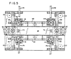
- the mould box is suitably mounted, at opposite sides thereof, to spaced-apart guide supports 112,114, which are, in turn, non-rigidly and flexibly mounted on the frame by elongate, metallic plate springs 116,118,120,122 (see Figures 2, 3 and 4) which may flex.
- a first power driven means 124 is mounted on the frame, and is interconnected by a timing belt drive 126 to a vibrator housing 128 which includes an internal eccentric arrangement for imparting vibration to a vertically extending vibrator rod 130, which is bolted to guide support 112 as shown.
- a horizontally extending first shaft 132 which is driven by first power driven means 124, extends from vibrator housing 128 to vibrator housing 134 which in turn is provided with an eccentric arrangement to impart vibration to vibrator rod 136 which is bolted to guide support 114.
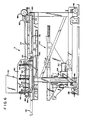
- a second power driven means 138 (see Figure 4) is suitably coupled to a vibrator housing 140 for imparting vibration to vibrator rod 142 and, via a second shaft means 143, imparting vibration to vibrator rod 144 (see Figure 3).
- the vibrators are defined by a first pair of spaced-apart, vertically extending vibrator rods 130,136 each having one end thereof connected to the mould box and the other end to first power driven means 124.
- the second set of vibrators is defined by a second pair of spaced-apart vertically extending vibrator rods 142, 144, each also having one end thereof connected to the mould box and the other to second power driven means 138.
- first pair of vibrator rods 130,136 can either by synchronised or operated independently from the second pair of vibrator rods 142,144. This becomes important when it is understood that it is desirable to have the flexibility of imparting vibration to the mould box, after it has been filled, or to impart vibration to one end of the mould box as will become apparent when the operation of the apparatus is described later.
- the first feed drawer assembly 12 is mounted on a frame structure which in turn is mounted on wheels 146,148 for enabling movement along a track, thereby to shift the assembly away from central block forming section 14 when it is desired to clean or maintain the unit.
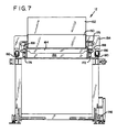
- first feed drawer assembly 12 comprises a normally stationary box 150 having a hopper 152 mounted thereon. Extending from opposite sides of box 150 are arms 154 (see also Figure 7) which are journalled to a pair of wheels 156,158 on each side, which are movable along associated tracks, such as tracks 160,162 as shown in Figure 7. Disposed beneath box 150 is a relatively shiftable first feed drawer 164, which is provided with a vertically adjustable "strike-off" or screed plate 166.
- track 172 is shown extending through central block forming section 14 and to the left of Figure 1, the second feed drawer assembly comprises a structure similar to that just described for the first feed drawer assembly 12, except it does not include a pallet feeder assembly such as generally indicated at 200 in Figure 1.
- Pallet feeder assembly 200 shown in greater detail in Figure 8, comprises a lifting means 202 which will receive pallets, such as indicated at 80, 81 etc.
- the lifting means is powered by a lifting cylinder/rod assembly 206 so that the pallet may be shifted upwardly, as indicated by the arrows so that the pallet will be raised to the position indicated at 80a.
- a pusher rod 208 is selectively actuated by a power driven cylinder 210 to engage an end of the pallet and shift it to the left, so that the pallet will be displaced onto the pallet table 78.
- a motor 212 is suitably interconnected via a gear box 214 and transmission means 216 to wheel 146 so that the first feed drawer assembly and supporting frame may be shifted away from central block forming section 14.
- a similar construction is provided for second feed drawer assembly 16.
- a locking/release mechanism interconnecting the systems is shown at 218.
- rail 172 is shown in Figures 1 and 6 as being continuous, the rails will in fact be comprised of separate, alignable sections to enable the first and second feed drawer assemblies to be shifted away from central block forming section 14 when maintenance or repair is required.
- Cylinders 50,56 are actuated so as to extend their corresponding rods 52,58, respectively, to displace compression beam 28 so that it extends to the position indicated at A in Figure 2.
- pallet feeder assembly 200 is actuated to shift a pallet onto pallet table 78. A pallet is disposed in that position as shown in Figures 2-4.
- cylinders 74,76 are actuated to displace stripper beam 30 vertically, so that the top of pallet 80 is positioned directly beneath mould box 100.
- First feed drawer 164 filled with concrete material, is then shifted toward block forming section 14, i.e. to the left with reference to Figures 1 and 6.
- First feed drawer 164 filled with concrete material
- block forming section 14 i.e. to the left with reference to Figures 1 and 6.
- concrete material is dispensed into the first cavities of the mould box, and as the first feed drawer continues moving over the mould box, the remaining cavities are filled with concrete material.
- agitator rod 173 is actuated so that the concrete material is continuously stirred up.
- Figure 2 shows positioning of first feed drawer 164 over mould box 100 after the first feed drawer has travelled along rails 172,174. Because the feed drawer is bottomless, it has displaced concrete material into the individual cavities, such as those indicated at 102,104,106 etc. The concrete materials fills each cavity substantially, and pallet 80 forms a bottom retainer.
- FIG. 9 An enlarged and broken-away schematic view of the first feed drawer above the mould box is shown in Figure 9.
- the mass of concrete material will not be evenly distributed in each cavity, inasmuch as those cavities which are initially filled will have a greater density than those subsequently filled. That is because the concrete material within the first feed drawer is deepest over the initially filled cavities, resulting in a denser mass there.
- the density of concrete material will be less in the cavities to the left, such as indicated at 100.
- Those cavities closest to the leading edge 100a of the mould box will have a more dense initial compaction of concrete material. However, it is desired to even out the densities in the cavities, so that each contains an equal mass of material.
- Vibrator rods 130, 136 are furthest from the cavities which were initially filled, and continued operation of those rods results in more vibration in the downstream end of the mould box ensuring more even distribution of material. This may be accomplished with feed drawer 164 positioned above mould box 100. Either pair of vibrator rods may be actuated, with the other shut down, to achieve a desired distribution of concrete material.
- the compression step occurs as follows. Compression cylinders 50,56 are actuated to retract their associated rods 52,58 to a position whereby shoes 40a,42a etc are directed downwardly into the cavities of mould box 100 to compress and compact the concrete material.
- compression stage typically all four of the vibrator rods may be driven for vibration of the mould box, or alternatively, a selected pair may be activated while the other pair is shut down. In any case, it is contemplated that it is preferable to provide vibration and compaction simultaneously, and synchronisation or independent operation of the first and second power driven means is possible depending upon the circumstances.
- first feed drawer 164 provided with base material of concrete, initially invests or fills the mould box. Vibration means 98 may be suitably actuated to provide vibration, as described above.
- the feed drawer of second feed drawer assembly 16 filled with concrete material having a different colour, is shifted into position so that the new material is dispensed on top of the original base material, thereby providing a colour cap.
- the second feed drawer is withdrawn, and compression beams and stripper beams are then actuated for providing the compression and strip-off steps, as described above. Again, vibration may be provided as needed whenever necessary. Pavers having such a colour cap are highly decorative, and find many applications in sidewalks, mall areas etc.
- the pairs of vibrator rods are mounted on their associated eccentric drives so that they can travel over a range of 2 mm from the bottom dead centre (BDC) to top dead centre (TDC).
- BDC bottom dead centre
- TDC top dead centre
- the mould box can correspondingly be moved that distance, or by suitable command, some selected shorter distance.
- one end of the mould box may be moved relative to the other by suitably commanding operation of a selected pair of the vibrator rods.
- An operator has flexibility to adjust the distribution of concrete material in the mould box to provide even distribution.
- the profile of the concrete material can be varied as the feed drawer is retracted. It is important to note that it is the mould box which has vibration imparted thereto.
- Another advantage of the present invention resides in the provision of rails or tracks which extend from one feed drawer assembly through the central block forming section and continue on into the second feed drawer assembly. It is not necessary that the rails, such as indicated at 172,174 actually form continuous members, but rather that a rail system is provided so that feed drawers which are laterally opposed on opposite sides of the mould box may be operable for rectilinear shifting therealong from a first position remote from the mould box to a second position disposed directly thereabove so that the investing step may take place. It is important to note that the positioning of rails 172, 174 effectively isolates the feed drawers from the mould box.
- a typical sequence might involve imparting vibration during the investment step for approximately 2-3 seconds. After investment, only one pair of the vibrators may be run for about 1 second. Different sequences are available according to type of concrete material, etc.
Landscapes
- Engineering & Computer Science (AREA)
- Manufacturing & Machinery (AREA)
- Chemical & Material Sciences (AREA)
- Ceramic Engineering (AREA)
- Mechanical Engineering (AREA)
- Devices For Post-Treatments, Processing, Supply, Discharge, And Other Processes (AREA)
- Press-Shaping Or Shaping Using Conveyers (AREA)
- On-Site Construction Work That Accompanies The Preparation And Application Of Concrete (AREA)
- Moulds, Cores, Or Mandrels (AREA)
- Artificial Fish Reefs (AREA)
Applications Claiming Priority (2)
| Application Number | Priority Date | Filing Date | Title |
|---|---|---|---|
| US383054 | 1989-07-21 | ||
| US07/383,054 US5059110A (en) | 1989-07-21 | 1989-07-21 | Apparatus for forming concrete blocks having plural separately driven vibrator sets |
Publications (3)
| Publication Number | Publication Date |
|---|---|
| EP0409471A2 true EP0409471A2 (fr) | 1991-01-23 |
| EP0409471A3 EP0409471A3 (en) | 1991-10-09 |
| EP0409471B1 EP0409471B1 (fr) | 1995-02-15 |
Family
ID=23511511
Family Applications (1)
| Application Number | Title | Priority Date | Filing Date |
|---|---|---|---|
| EP90307564A Expired - Lifetime EP0409471B1 (fr) | 1989-07-21 | 1990-07-11 | Dispositif pour la fabrication de blocs en béton |
Country Status (7)
| Country | Link |
|---|---|
| US (1) | US5059110A (fr) |
| EP (1) | EP0409471B1 (fr) |
| KR (1) | KR0161275B1 (fr) |
| AT (1) | ATE118397T1 (fr) |
| AU (1) | AU632808B2 (fr) |
| CA (1) | CA2018214C (fr) |
| DE (1) | DE69016864T2 (fr) |
Cited By (7)
| Publication number | Priority date | Publication date | Assignee | Title |
|---|---|---|---|---|
| GB2292105A (en) * | 1994-08-10 | 1996-02-14 | Kameel Diab Sawalha | System for producing discrete components or articles from continous fibre metal matrix composite |
| FR2729602A1 (fr) * | 1995-01-25 | 1996-07-26 | Adler Sa | Procede de moulage sous pression, et installation pour la mise en oeuvre de ce procede |
| CN1036980C (zh) * | 1992-06-15 | 1998-01-14 | 冶金工业部钢铁研究总院 | 混凝土轨枕构件振动成型装置 |
| ES2135302A1 (es) * | 1996-02-07 | 1999-10-16 | Medrano Bermejo Maria Carmen | Maquina para la fabricacion de tableros de hormigon prefabricados. |
| ES2140273A1 (es) * | 1996-11-05 | 2000-02-16 | Diprom 2 000 S L | Procedimiento para la fabricacion de elementos de balaustrada de hormigon en masa y maquina correspondiente. |
| US7807089B2 (en) * | 2005-03-30 | 2010-10-05 | Godelmann Pflasterstein Gmbh & Co. Kg | Method and mold for manufacturing ground slabs made of cement-bonded material or concrete |
| CN106426520A (zh) * | 2016-11-08 | 2017-02-22 | 山东建筑大学 | 双工位混凝土构件成型机 |
Families Citing this family (15)
| Publication number | Priority date | Publication date | Assignee | Title |
|---|---|---|---|---|
| KR0180557B1 (ko) * | 1990-12-26 | 1999-03-20 | 후까이 히로도시 | 벽돌 압착기 |
| US5807591A (en) * | 1994-07-28 | 1998-09-15 | Columbia Machine, Inc. | Method and apparatus for forming concrete products |
| US5395228A (en) * | 1994-02-07 | 1995-03-07 | Columbia Machine, Inc. | Apparatus for forming concrete products |
| US5542837A (en) * | 1995-01-13 | 1996-08-06 | Columbia Machine, Inc. | Mold box assembly with partition plates |
| US5866026A (en) * | 1995-06-01 | 1999-02-02 | Columbia Machine, Inc. | Method and apparatus for accommodating tolerances in a mold for concrete products |
| US6007321A (en) * | 1997-09-04 | 1999-12-28 | Meckel; Kevin | Unitary paver mold |
| US5939104A (en) * | 1998-02-11 | 1999-08-17 | Columbia Machine, Inc. | Apparatus for forming a multilevel concrete product |
| RU2140353C1 (ru) * | 1999-04-13 | 1999-10-27 | Открытое акционерное общество "Экспостроймаш" | Агрегат для формования изделий из строительных смесей |
| US6758665B2 (en) * | 2000-12-07 | 2004-07-06 | Sigmund P. Cichos | Concrete block vibrator |
| RU2353514C1 (ru) * | 2007-11-15 | 2009-04-27 | Набатников Сергей Александрович | Вибропресс и способ вибропрессования с его использованием |
| DE102009050731A1 (de) * | 2009-10-26 | 2011-04-28 | Outotec Oyj | Anlage zur Herstellung eines für die Verkokung geeigneten Kohlekuchens |
| US9492944B2 (en) * | 2013-11-25 | 2016-11-15 | Ness Inventions, Inc. | Agitator grid with adjustable restrictor elements for concrete block machine |
| KR101692518B1 (ko) * | 2016-04-19 | 2017-01-03 | (주)한보이엔지 | 방진고무 보호 구조를 갖는 옹벽블록 제조장치 |
| CN107839287A (zh) * | 2017-11-28 | 2018-03-27 | 合肥波林新材料股份有限公司 | 一种粉末成形送料装置 |
| CN111775274A (zh) * | 2020-06-23 | 2020-10-16 | 陈悦锋 | 一种水泥板制作装置 |
Family Cites Families (18)
| Publication number | Priority date | Publication date | Assignee | Title |
|---|---|---|---|---|
| US2985935A (en) * | 1961-05-30 | Control system for a concrete block forming machine | ||
| US2396999A (en) * | 1945-02-22 | 1946-03-19 | Frank C George | Block molding machine |
| US2706320A (en) * | 1948-12-06 | 1955-04-19 | Neth Fred | Concrete block machine |
| US2589115A (en) * | 1948-12-06 | 1952-03-11 | Neth Fred | Machine for making concrete blocks |
| US2859502A (en) * | 1952-04-18 | 1958-11-11 | Jr Charles Kepler Brown | Block molding machine |
| US2819046A (en) * | 1953-11-13 | 1958-01-07 | Albert C Jandris | Vibration absorbing apparatus |
| US2842827A (en) * | 1955-01-14 | 1958-07-15 | Richmond Foundry & Mfg Co Inc | Block forming machine |
| US3343239A (en) * | 1965-01-27 | 1967-09-26 | Columbia Machine | Concrete block forming machine with pneumatic vibration |
| US3331112A (en) * | 1966-05-10 | 1967-07-18 | Raymond W Clanton | Machine for molding concrete blocks |
| DE1758927B1 (de) * | 1968-09-04 | 1970-12-17 | Vaw Ver Aluminium Werke Ag | Ruettelvorrichtung zur Herstellung von Kohle-Elektroden hoher Dichte fuer die Aluminium-Industrie |
| US3659986A (en) * | 1970-03-16 | 1972-05-02 | Nathan L Gelbman | Apparatus for making concrete products |
| US4111627A (en) * | 1977-03-29 | 1978-09-05 | Kabushiki Kaisha Tiger Machine Seisakusho | Apparatus for molding concrete-blocks |
| JPS5424922A (en) * | 1977-07-26 | 1979-02-24 | Katsura Kikai Seisakushiyo Kk | Vibration equipment for concrete block molding machine |
| US4238177A (en) * | 1978-04-24 | 1980-12-09 | Crile Eugene E | Molding machine with vibration isolation |
| US4265609A (en) * | 1978-07-19 | 1981-05-05 | Yutaka Kitahara | Method and apparatus for molding concrete block products |
| FR2478519A1 (fr) * | 1980-03-24 | 1981-09-25 | Mfp Di Manfio Alberto C | Machine automatique pour la confection d'elements prefabriques en pate de ciment |
| DE3040876A1 (de) * | 1980-10-30 | 1982-06-09 | Kronimus & Sohn Betonsteinwerk und Baugeschäft GmbH & Co KG, 7551 Iffezheim | Verfahren zur herstellung von kuenstlichen pflastersteinen unter verwendung von betonmischung/en |
| US4445839A (en) * | 1982-09-16 | 1984-05-01 | Metalfab, Inc. | Reciprocating tamper for a concrete mold press |
-
1989
- 1989-07-21 US US07/383,054 patent/US5059110A/en not_active Expired - Lifetime
-
1990
- 1990-05-15 AU AU55044/90A patent/AU632808B2/en not_active Expired
- 1990-06-04 CA CA002018214A patent/CA2018214C/fr not_active Expired - Fee Related
- 1990-07-11 DE DE69016864T patent/DE69016864T2/de not_active Expired - Lifetime
- 1990-07-11 EP EP90307564A patent/EP0409471B1/fr not_active Expired - Lifetime
- 1990-07-11 AT AT90307564T patent/ATE118397T1/de not_active IP Right Cessation
- 1990-07-21 KR KR1019900011100A patent/KR0161275B1/ko not_active Expired - Fee Related
Cited By (8)
| Publication number | Priority date | Publication date | Assignee | Title |
|---|---|---|---|---|
| CN1036980C (zh) * | 1992-06-15 | 1998-01-14 | 冶金工业部钢铁研究总院 | 混凝土轨枕构件振动成型装置 |
| GB2292105A (en) * | 1994-08-10 | 1996-02-14 | Kameel Diab Sawalha | System for producing discrete components or articles from continous fibre metal matrix composite |
| GB2292105B (en) * | 1994-08-10 | 1999-03-17 | Kameel Diab Sawalha | System for producing discrete components or articles from continuous fibre metal matrix composite |
| FR2729602A1 (fr) * | 1995-01-25 | 1996-07-26 | Adler Sa | Procede de moulage sous pression, et installation pour la mise en oeuvre de ce procede |
| ES2135302A1 (es) * | 1996-02-07 | 1999-10-16 | Medrano Bermejo Maria Carmen | Maquina para la fabricacion de tableros de hormigon prefabricados. |
| ES2140273A1 (es) * | 1996-11-05 | 2000-02-16 | Diprom 2 000 S L | Procedimiento para la fabricacion de elementos de balaustrada de hormigon en masa y maquina correspondiente. |
| US7807089B2 (en) * | 2005-03-30 | 2010-10-05 | Godelmann Pflasterstein Gmbh & Co. Kg | Method and mold for manufacturing ground slabs made of cement-bonded material or concrete |
| CN106426520A (zh) * | 2016-11-08 | 2017-02-22 | 山东建筑大学 | 双工位混凝土构件成型机 |
Also Published As
| Publication number | Publication date |
|---|---|
| KR0161275B1 (ko) | 1998-11-16 |
| ATE118397T1 (de) | 1995-03-15 |
| US5059110A (en) | 1991-10-22 |
| DE69016864D1 (de) | 1995-03-23 |
| AU632808B2 (en) | 1993-01-14 |
| AU5504490A (en) | 1991-01-24 |
| EP0409471A3 (en) | 1991-10-09 |
| EP0409471B1 (fr) | 1995-02-15 |
| CA2018214A1 (fr) | 1991-01-21 |
| KR910002571A (ko) | 1991-02-25 |
| CA2018214C (fr) | 1995-05-23 |
| DE69016864T2 (de) | 1995-08-03 |
Similar Documents
| Publication | Publication Date | Title |
|---|---|---|
| EP0409471B1 (fr) | Dispositif pour la fabrication de blocs en béton | |
| US5219591A (en) | Apparatus for forming concrete blocks | |
| JP4121581B2 (ja) | コンクリート製品の成形方法及びコンクリート製品成形装置 | |
| US7635261B2 (en) | Large pallet machine for forming molded products | |
| US6177039B1 (en) | Method for forming concrete products | |
| US2859502A (en) | Block molding machine | |
| US3181222A (en) | Machine for manufacture of prestressed concrete conduit | |
| CN110181653B (zh) | 一种预应力构件滑移铺筑成型机 | |
| US3331112A (en) | Machine for molding concrete blocks | |
| US4457682A (en) | Machine for casting concrete members | |
| RU111802U1 (ru) | Устройство для прессования изделий из строительных смесей | |
| US3264702A (en) | Machine for molding concrete blocks | |
| RU2220044C1 (ru) | Агрегат для формования изделий из полусухих строительных смесей | |
| US6758665B2 (en) | Concrete block vibrator | |
| NZ203766A (en) | Brick moulding apparatus: die between two movable platens | |
| RU2044638C1 (ru) | Установка для прессования изделий из строительных смесей | |
| RU2203802C1 (ru) | Агрегат для формования изделий из строительных смесей | |
| SU1454697A1 (ru) | Установка дл непрерывного формовани многопустотных изделий из бетонных смесей | |
| RU2694671C1 (ru) | Комплекс формовочный стационарный для производства бетонных изделий | |
| SU887169A1 (ru) | Виброударна установка дл формовани строительных изделий | |
| SU1532186A1 (ru) | Формовочна машина | |
| SU948667A1 (ru) | Роторный конвейер дл изготовлени бетонных и железобетонных изделий | |
| RU2053879C1 (ru) | Установка для изготовления изделий из бетонных смесей | |
| CN1012888B (zh) | 滑模推压机 | |
| DE19758123A1 (de) | Arbeitsverfahren zum Herstellen maßgenauer Betonsteine |
Legal Events
| Date | Code | Title | Description |
|---|---|---|---|
| PUAI | Public reference made under article 153(3) epc to a published international application that has entered the european phase |
Free format text: ORIGINAL CODE: 0009012 |
|
| AK | Designated contracting states |
Kind code of ref document: A2 Designated state(s): AT BE CH DE DK ES FR GB IT LI NL SE |
|
| PUAL | Search report despatched |
Free format text: ORIGINAL CODE: 0009013 |
|
| AK | Designated contracting states |
Kind code of ref document: A3 Designated state(s): AT BE CH DE DK ES FR GB IT LI NL SE |
|
| 17P | Request for examination filed |
Effective date: 19920408 |
|
| 17Q | First examination report despatched |
Effective date: 19930205 |
|
| GRAA | (expected) grant |
Free format text: ORIGINAL CODE: 0009210 |
|
| AK | Designated contracting states |
Kind code of ref document: B1 Designated state(s): AT BE CH DE DK ES FR GB IT LI NL SE |
|
| PG25 | Lapsed in a contracting state [announced via postgrant information from national office to epo] |
Ref country code: AT Effective date: 19950215 Ref country code: LI Effective date: 19950215 Ref country code: NL Effective date: 19950215 Ref country code: BE Effective date: 19950215 Ref country code: CH Effective date: 19950215 Ref country code: DK Effective date: 19950215 Ref country code: FR Effective date: 19950215 |
|
| REF | Corresponds to: |
Ref document number: 118397 Country of ref document: AT Date of ref document: 19950315 Kind code of ref document: T |
|
| REF | Corresponds to: |
Ref document number: 69016864 Country of ref document: DE Date of ref document: 19950323 |
|
| ITF | It: translation for a ep patent filed | ||
| PG25 | Lapsed in a contracting state [announced via postgrant information from national office to epo] |
Ref country code: SE Effective date: 19950515 |
|
| PG25 | Lapsed in a contracting state [announced via postgrant information from national office to epo] |
Ref country code: ES Free format text: LAPSE BECAUSE OF FAILURE TO SUBMIT A TRANSLATION OF THE DESCRIPTION OR TO PAY THE FEE WITHIN THE PRESCRIBED TIME-LIMIT Effective date: 19950526 |
|
| REG | Reference to a national code |
Ref country code: CH Ref legal event code: PL |
|
| EN | Fr: translation not filed | ||
| NLV1 | Nl: lapsed or annulled due to failure to fulfill the requirements of art. 29p and 29m of the patents act | ||
| PGFP | Annual fee paid to national office [announced via postgrant information from national office to epo] |
Ref country code: ES Payment date: 19950727 Year of fee payment: 6 Ref country code: NL Payment date: 19950727 Year of fee payment: 6 |
|
| PLBE | No opposition filed within time limit |
Free format text: ORIGINAL CODE: 0009261 |
|
| STAA | Information on the status of an ep patent application or granted ep patent |
Free format text: STATUS: NO OPPOSITION FILED WITHIN TIME LIMIT |
|
| 26N | No opposition filed | ||
| PGFP | Annual fee paid to national office [announced via postgrant information from national office to epo] |
Ref country code: GB Payment date: 19970702 Year of fee payment: 8 |
|
| PG25 | Lapsed in a contracting state [announced via postgrant information from national office to epo] |
Ref country code: GB Free format text: LAPSE BECAUSE OF NON-PAYMENT OF DUE FEES Effective date: 19980711 |
|
| GBPC | Gb: european patent ceased through non-payment of renewal fee |
Effective date: 19980711 |
|
| PGFP | Annual fee paid to national office [announced via postgrant information from national office to epo] |
Ref country code: DE Payment date: 20090709 Year of fee payment: 20 |
|
| PGFP | Annual fee paid to national office [announced via postgrant information from national office to epo] |
Ref country code: IT Payment date: 20090722 Year of fee payment: 20 |
|
| PG25 | Lapsed in a contracting state [announced via postgrant information from national office to epo] |
Ref country code: DE Free format text: LAPSE BECAUSE OF EXPIRATION OF PROTECTION Effective date: 20100711 |