EP0409491A2 - Magnetisches Behandlungsverfahren für Wasser für die Landwirtschaft - Google Patents
Magnetisches Behandlungsverfahren für Wasser für die Landwirtschaft Download PDFInfo
- Publication number
- EP0409491A2 EP0409491A2 EP90307659A EP90307659A EP0409491A2 EP 0409491 A2 EP0409491 A2 EP 0409491A2 EP 90307659 A EP90307659 A EP 90307659A EP 90307659 A EP90307659 A EP 90307659A EP 0409491 A2 EP0409491 A2 EP 0409491A2
- Authority
- EP
- European Patent Office
- Prior art keywords
- water
- magnetic
- magnetic field
- livestock
- treated
- Prior art date
- Legal status (The legal status is an assumption and is not a legal conclusion. Google has not performed a legal analysis and makes no representation as to the accuracy of the status listed.)
- Granted
Links
- XLYOFNOQVPJJNP-UHFFFAOYSA-N water Substances O XLYOFNOQVPJJNP-UHFFFAOYSA-N 0.000 title claims abstract description 119
- 230000005291 magnetic effect Effects 0.000 title claims abstract description 69
- 244000144972 livestock Species 0.000 claims abstract description 12
- 239000002245 particle Substances 0.000 claims abstract description 10
- 230000005294 ferromagnetic effect Effects 0.000 claims abstract description 5
- 230000000694 effects Effects 0.000 claims abstract 2
- 230000002262 irrigation Effects 0.000 claims description 12
- 238000003973 irrigation Methods 0.000 claims description 12
- 239000000696 magnetic material Substances 0.000 claims description 12
- 239000003651 drinking water Substances 0.000 claims description 9
- 235000020188 drinking water Nutrition 0.000 claims description 9
- 238000000034 method Methods 0.000 claims description 9
- 241001465754 Metazoa Species 0.000 claims description 8
- 230000035622 drinking Effects 0.000 claims description 6
- 238000001816 cooling Methods 0.000 claims description 5
- 238000004140 cleaning Methods 0.000 claims description 4
- 238000001704 evaporation Methods 0.000 claims description 4
- 230000008020 evaporation Effects 0.000 claims description 4
- 238000001914 filtration Methods 0.000 claims description 4
- 239000007788 liquid Substances 0.000 claims description 4
- 229910000531 Co alloy Inorganic materials 0.000 claims description 3
- -1 aluminum-nickel-cobalt Chemical compound 0.000 claims description 3
- 239000003337 fertilizer Substances 0.000 claims description 3
- 238000003860 storage Methods 0.000 claims description 3
- 239000003621 irrigation water Substances 0.000 claims description 2
- 229910052761 rare earth metal Inorganic materials 0.000 claims description 2
- 239000007921 spray Substances 0.000 claims description 2
- 238000005086 pumping Methods 0.000 claims 2
- 238000011144 upstream manufacturing Methods 0.000 claims 1
- 244000144977 poultry Species 0.000 description 6
- 241000283690 Bos taurus Species 0.000 description 5
- 238000005260 corrosion Methods 0.000 description 5
- 230000007797 corrosion Effects 0.000 description 5
- 238000011010 flushing procedure Methods 0.000 description 5
- 230000005405 multipole Effects 0.000 description 5
- 230000009471 action Effects 0.000 description 3
- 238000007792 addition Methods 0.000 description 3
- 230000012010 growth Effects 0.000 description 3
- 230000003134 recirculating effect Effects 0.000 description 3
- 238000012360 testing method Methods 0.000 description 3
- RYGMFSIKBFXOCR-UHFFFAOYSA-N Copper Chemical compound [Cu] RYGMFSIKBFXOCR-UHFFFAOYSA-N 0.000 description 2
- 230000015572 biosynthetic process Effects 0.000 description 2
- 229910052802 copper Inorganic materials 0.000 description 2
- 239000010949 copper Substances 0.000 description 2
- 230000001419 dependent effect Effects 0.000 description 2
- 238000002474 experimental method Methods 0.000 description 2
- 230000004907 flux Effects 0.000 description 2
- 230000006872 improvement Effects 0.000 description 2
- 239000012528 membrane Substances 0.000 description 2
- 239000000126 substance Substances 0.000 description 2
- 238000012546 transfer Methods 0.000 description 2
- 241000282414 Homo sapiens Species 0.000 description 1
- 241001494479 Pecora Species 0.000 description 1
- 241000282849 Ruminantia Species 0.000 description 1
- 229910000831 Steel Inorganic materials 0.000 description 1
- 241000282898 Sus scrofa Species 0.000 description 1
- 238000009825 accumulation Methods 0.000 description 1
- 238000009360 aquaculture Methods 0.000 description 1
- 244000144974 aquaculture Species 0.000 description 1
- 230000009286 beneficial effect Effects 0.000 description 1
- 230000015556 catabolic process Effects 0.000 description 1
- 238000013461 design Methods 0.000 description 1
- 230000029087 digestion Effects 0.000 description 1
- 238000009826 distribution Methods 0.000 description 1
- 235000013399 edible fruits Nutrition 0.000 description 1
- 239000003792 electrolyte Substances 0.000 description 1
- 239000013505 freshwater Substances 0.000 description 1
- 239000012535 impurity Substances 0.000 description 1
- 238000001727 in vivo Methods 0.000 description 1
- 229910052500 inorganic mineral Inorganic materials 0.000 description 1
- 150000002500 ions Chemical class 0.000 description 1
- 230000005415 magnetization Effects 0.000 description 1
- 238000004519 manufacturing process Methods 0.000 description 1
- 239000000463 material Substances 0.000 description 1
- 235000013372 meat Nutrition 0.000 description 1
- 230000004060 metabolic process Effects 0.000 description 1
- 239000008267 milk Substances 0.000 description 1
- 210000004080 milk Anatomy 0.000 description 1
- 235000013336 milk Nutrition 0.000 description 1
- 239000011707 mineral Substances 0.000 description 1
- 238000012986 modification Methods 0.000 description 1
- 230000004048 modification Effects 0.000 description 1
- 230000008635 plant growth Effects 0.000 description 1
- 239000010865 sewage Substances 0.000 description 1
- 239000010959 steel Substances 0.000 description 1
- 239000008399 tap water Substances 0.000 description 1
- 235000020679 tap water Nutrition 0.000 description 1
Images


Classifications
-
- C—CHEMISTRY; METALLURGY
- C02—TREATMENT OF WATER, WASTE WATER, SEWAGE, OR SLUDGE
- C02F—TREATMENT OF WATER, WASTE WATER, SEWAGE, OR SLUDGE
- C02F1/00—Treatment of water, waste water, or sewage
- C02F1/48—Treatment of water, waste water, or sewage with magnetic or electric fields
- C02F1/481—Treatment of water, waste water, or sewage with magnetic or electric fields using permanent magnets
Definitions
- the present invention relates to a method and to a device for the magnetic treatment of water used in agriculture, particularly for irrigation of plants and for watering of domestic animals.
- Magnetic treatment of water and other liquids has been known for a number of years, the purpose of the treatment being preventing build-up of scale in the pipes and vessels through which the water flows.
- the devices used for this treatment comprise essentially a multi-pole magnet positioned in an inner casing of a non-magnetic material, concentrically mounted in an outer tubular casing of a magnetic material, water flowing along the annular duct formed between the inner and the outer casing.
- the magnet creates a strong magnetic field which has an outer limit defined by the outer casing of magnetic material.
- the treatment deforms the molecules of the suspended minerals in a way preventing their adhering to the walls of the pipes and vessels along which they flow and thus preventing formation of scale.
- the molecules return to their original alignment after a few hours, and it is known that for recirculating water or other liquids the treatment is advantageously repeated for every circuit.
- Multi-pole magnets for this purpose were originally manufactured by Kentune Inc., Fort Wayne, U.S.A, and they are still the most suitable for this kind of treatment.
- the original patent having expired, various modifications and additions to the original design have been patented, by the above firm and by others, with the object of either better securing the magnet or for treating only a given part of the water, as in the case of vehicle cooling by recirculation through a radiator, or with other purposes in mind.
- apparatus for magnetic treatment as well as the water flow conditions should preferably fulfill the following conditions:- 1) laminar or nearly laminar flow; 2) vertical upwards flow through the treatment device; 3) magnetic flux density to be between 0.095 and 0.32 tesla (between 950 and 3200 gauss); 4) the alternating multi-pole magnets to contain from 4 to 8 poles; 5) magnetic field vector to be substantially perpendicular to water flow vector; 6) spacing and numbers of poles to be determined so as to obtain a predetermined frequency of polarity acting on the water molecules at a predetermined flow velocity; 7) means to be provided to keep the device clean and free of scale and dirt accumulation; 8) both a cover of non-magnetic material as well as a tubular casing of magnetic material to be protected against corrosion and pitting by chemical action or by magneto-hydrodynamically generated voltage; 9) temperature of the water flowing through the device to be below 80°C.
- the present invention provides a method of magnetically treating water for use in irrigation of planted fields and in watering of domestic animals comprising mechanically cleaning the water so as to remove ferromagnetic particles and other suspended matter, and causing the water to pass through a magnetic field of alternating polarity, wherein said magnetic field is of an intensity of between 600 and 6500 gauss and a field gradient of between 0.2 and 6.0 kgauss/cm, said water flow through said magnetic field is in substantially perpendicular direction to the magnetic field vector, said water flow through said magnetic field is substantially laminar, at a velocity of between 0.5 and 2.4 m/s, and said laminar water flow is at a velocity causing each water particle to pass through said magnetic field of alternating polarity at a frequency of not less than 2 and not more than 60 polarity changes per second.
- magnetic treatment of water for irrigation of plants and for watering of domestic animals may be carried out by causing raw water to flow through a device which comprises at least one magnetic unit comprising: an elongate, alternating multi-pole magnet mounted inside the device in substantially vertical alignment, the magnet comprising between 4 and 8 axially spaced poles; an inner casing of a non-magnetic material encasing and protecting the multi-pole magnet; an outer casing of a magnetic material of a cross section larger than the cross section of the inner casing and surrounding the inner casing and the magnet in co-axial alignment, forming an annular water duct therebetween which communicates at its bottom end with the water inlet and at its top end with the water outlet; hydrodynamic means for straightening the water flow at the entrance to the annular duct, to create a substantially laminar flow along the magnet; means for mechanical filtration of the water before its entrance into the magnetic unit with the object of removing ferromagnetic particles and other suspended matter; and means for backflushing and cleaning the
- a streamlined end cover is attached to the inner casing at its bottom end and/or its top end, to cause laminar flow along the annular duct.
- the device With the object of cleaning the device from time to time, it is incorporated in a circuit which includes a bypass around the device and the necessary valves for directing the water flow in opposite direction, i.e. from top to bottom and into the open through a spillway.
- Backflushing may be carried out manually or automatically by means of a timer adjusted to operate several solenoid valves at certain hours of the day or, alternatively, after a given throughflow of raw water through the device.
- two or more units may be advantageously placed in parallel alignment, whereby the two or more units are incorporated in a circuit which is provided with backflushing devices as well as a recirculating pump, if the water is to be used as drinking water for domestic animals.
- a preferred embodiment consists in a storage tank containing a splash plate mounted above water level onto which the water returning from the magnetic unit is directed, whereby the increased surface causes strong evaporation and thereby lowering of the water temperature.
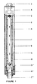
- the magnetic treatment unit shown in Figure 1 comprises an elongated permanent magnet 1 provided with six poles marked by "N”and “S”, which is generally manufactured of a aluminum-nickel-cobalt alloy (ALNICO).
- the magnet is covered by an inner casing 2 of copper or another non-magnetic material which protects the magnet against attack by the water flowing through the unit.
- Two stream-lined covers 3 and 3′ are attached to the ends of magnet 1 and casing 2 ensuring formation of a laminar flow through the unit, provided the flow velocity is kept within the proper limits, i.e. below the critical Reynolds Number.
- the outer casing is fastened in two end fitting 6 and 6′ by means of screw thread, these fittings serving for connecting the unit to an inlet and outlet pipe 7 respectively.
- An outer shell 8 of copper or another non-magnetic material connects the two end fittings and protects the entire unit against mechanical damage, while being spaced apart from the outer magnetic casing 4 and forming an air space 9 there-between.
- the unit is placed in vertical - or substantially vertical - alignment, with a view to ensure complete filling of the annular duct with water to be treated.
- the magnetic outer casing forms the outer limit for the magnetic field formed by the magnet poles which create a magnetic field of well-defined intensity, direction and distribution throughout the entire annular duct.
- Water enters the unit from below through the water inlet pipe 7′ and leaves it in treated condition at the top end through the outlet pipe 7.
- FIG. 2 illustrates a circuit for once-through magnetic treatment and for backflushing of a magnetic unit from time to time in order to prevent build-up of scale or dirt in the duct.
- the present embodiment of a circuit has a water inlet 11 and a water outlet 12 leading to piping for plant irrigation.
- the water flows through the magnetic unit M through a line containing a stop valve 13 and a filter 14 to the outlet 12 which can be closed by a stop valve 15 for flushing purposes.
- a bypass 16 connects the inlet 11 direct with the outlet 12 and is, in its turn, closed by a valve 17.
- the bottom end of the magnetic unit communicates with a flush-water outlet through a valve 18.
- valves 13 and 15 are open, whilst the valves 17 and 18 are closed, forcing all irrigation water through the magnetic unit.
- the valves 13 and 15 are closed and valves 17 and 18 are opened, thereby changing the direction of the water flow, forcing it through the magnetic unit from top to bottom and flushing out dirt and scale.
- the hand-operated valves shown in the drawing may be replaced by electrically operated valves, such as solenoid valves, to be actuated automatically, either after a certain period of irrigation or dependent on the measured throughflow.
- Figure 3 illustrates a circuit similar to that shown in Figure 2, however containing three magnetic units M1, M2 and M3 placed in vertical, parallel alignment. It is important that the distance between each two units is at least three times the magnet diameter, in order to prevent interference of the three magnetic fields.
- the piping and the arrangement of the valves is identical in both Figures 2 and 3, and for this reason the valves and lines are being denoted by the same numerals.
- the entire circuit is held and supported on a stand 20 which keeps the magnetic units in vertical position and permits its ready transfer from site to site.
- Magnetic treatment of drinking water for cattle is illustrated in Figure 4, showing a feed pipe 30 with a plurality of drinking troughs 31 attached thereto by means of automatic taps.
- the magnetic unit M is placed in a circuit which is adapted for recirculation of the drinking water flowing through the feed pipe 30 and through the magnetic unit; it is adapted for backflushing similarly as illustrated in Figures 2 and 3, and for this reason identical numerals are used for denoting identical or similar components.
- the recirculating circuit includes, additionally, a return pipe 32 extending from the tail end of the feed pipe 30, a circulating pump 33 and a check valve 34. Water returning from the feed pipe is pumped through the filter 14 and the unit M back into the feed pipe, while the check valve 34 prevents water from being pumped back into the supply pipe 11.
- the check valve opens as soon as the pump pressure drops due to an insufficient quantity of water returned from the feed pipe and causes fresh water to flow in from the supply. Backflushing is carried out as described with reference to Figures 2 or 3.
- the magnetic treatment circuit shown in Figure 5 is used in preparing drinking water for poultry.
- the drinking troughs are usually fed from a central overhead tank or container, preventing water shortage in case of a breakdown of the water supply, and the apparatus shown in Figure 5 is designed for re-treatment of the water in the tank which would, otherwise, lose its special properties after a few hours, as mentioned in the foregoing.
- the drawing shows an overhead tank 40 supplied raw water from a central supply 11 through a pipe 12 which terminates in a float valve 41 in order to prevent overflowing. Water is pumped out of the tank by a pump 33 through an outlet pipe 42 and conveyed to the magnetic unit M after having ferromagnetic particles and other suspended matter removed by a filter 14.
- the pump is designed to an output to ensure water velocity and magnetization of water at the predetermined frequency as described in the foregoing.
- the treated water flows into the tank through piping 44 and an overhead outlet from which it drops down onto a splash plate 43.
- the water leaves the splash plate in the form of a fine spray and flows down into the tank while being cooled by evaporation.
- Water to the drinking troughs 31 leaves the tank through an outlet pipe 30, while a pump 46 serves for returning the non-consumed water to the overhead tank via piping 45 and over the splash plate 43 for further cooling and for recirculation through the magnetic unit M.
- magnets should have between 4 to 8 poles, and that the magnetic field intensity should vary between 600 and 6500 gauss, with a magnetic field gradient of 0.2 - 6.0 mgauss/cm. These values dictate the dimensions of the magnets and the casings, and tests have shown that optimal values could be obtained with magnets of aluminum-nickel-cobalt alloys and of rare earth elements as known to the art. Magnets made from RER's are useful because they retain their high magnetic intensity.
- the flow velocity of the water in the annular duct should be between 0.5 and 2.4 m/s, so as to obtain substantially laminar flow in the annular duct, which also requires the fitting of streamlined caps to the ends of the magnet, which are, preferably but not necessarily, of parabolic cross section. Best results were obtained by chosing the flow velocity in a manner that each molecule passes each pair of alternating magnet poles between 2 to 60 times per second, i.e. at a frequency of 2-60 Hz. The flow velocity is therefore dependent on the number and spacing of the poles, as well as on the condition of laminar flow.
- Another important point for obtaining good results is to keep the water temperature below ambient temperature on hot days and in the hot season, which can be carried out by evaporation of a part of the water, either by means of separate cooling equipment or, in the case of an overhead tank, by splashing the incoming water on a flat plate, as described with reference to Figure 5.
- the water must have a minimum electric conductivity, but should be free of electromagnetic particles which have to be removed by mechanical filtering. Treatment results improve with increased conductivity, whereby tap water has usually low conductivity, while treated sewage and brackish water answer far better.
Landscapes
- Life Sciences & Earth Sciences (AREA)
- Hydrology & Water Resources (AREA)
- Engineering & Computer Science (AREA)
- Environmental & Geological Engineering (AREA)
- Water Supply & Treatment (AREA)
- Chemical & Material Sciences (AREA)
- Organic Chemistry (AREA)
- Water Treatment By Electricity Or Magnetism (AREA)
Applications Claiming Priority (2)
| Application Number | Priority Date | Filing Date | Title |
|---|---|---|---|
| IL9101489A IL91014A (en) | 1989-07-17 | 1989-07-17 | Magnetic treatment of water used for agricultural purpose |
| IL91014 | 1989-07-17 |
Publications (3)
| Publication Number | Publication Date |
|---|---|
| EP0409491A2 true EP0409491A2 (de) | 1991-01-23 |
| EP0409491A3 EP0409491A3 (en) | 1991-04-03 |
| EP0409491B1 EP0409491B1 (de) | 1993-03-24 |
Family
ID=11060185
Family Applications (1)
| Application Number | Title | Priority Date | Filing Date |
|---|---|---|---|
| EP90307659A Expired - Lifetime EP0409491B1 (de) | 1989-07-17 | 1990-07-12 | Magnetisches Behandlungsverfahren für Wasser für die Landwirtschaft |
Country Status (4)
| Country | Link |
|---|---|
| US (1) | US5009791A (de) |
| EP (1) | EP0409491B1 (de) |
| ES (1) | ES2041141T3 (de) |
| IL (1) | IL91014A (de) |
Cited By (6)
| Publication number | Priority date | Publication date | Assignee | Title |
|---|---|---|---|---|
| FR2705594A1 (fr) * | 1993-05-25 | 1994-12-02 | Fraysse Eric | Maintenance de circuits hydrauliques par nettoyage mécanique et protection magnétique. |
| ES2111460A1 (es) * | 1995-05-25 | 1998-03-01 | Magnetic Star Group S L | Procedimiento para la ionizacion magnetica de liquidos. |
| RU2126772C1 (ru) * | 1998-08-17 | 1999-02-27 | Общество с ограниченной ответственностью "Технобридж-Сервис" | Способ обеззараживания жидкой среды |
| WO2004022098A1 (en) * | 2002-09-09 | 2004-03-18 | Borsos Ferenc | Oxygen-enriched water, treated within a magnetic field and heavy water |
| EP1837032A4 (de) * | 2004-12-31 | 2009-06-10 | Mikhail Yurievich Gotovsky | Magnetresonanz-zubereitungen, vorrichtung zur individuellen auswahl dieser zubereitungen zur erhöhung der lebensaktivität eines organismus unter tatsächlichen umweltbedingungen |
| CN110332707A (zh) * | 2019-08-06 | 2019-10-15 | 刘明辉 | 一种水分子磁波震荡高能转换系统和方法 |
Families Citing this family (30)
| Publication number | Priority date | Publication date | Assignee | Title |
|---|---|---|---|---|
| DK136793D0 (da) * | 1993-12-07 | 1993-12-07 | Fjeldsend As Olaf | Methods of physical water treatment and apparatus therefor |
| US5584994A (en) * | 1994-11-25 | 1996-12-17 | Hattori; Toshimitsu | Apparatus for manufacturing magnetized water and magnetic force generator used therefor |
| US6099738A (en) * | 1997-12-17 | 2000-08-08 | Micromag Corporation | Method and system for removing solutes from a fluid using magnetically conditioned coagulation |
| US6390319B1 (en) | 1998-11-30 | 2002-05-21 | Sun Yu | Beverage magnetizing container |
| RU2191162C1 (ru) * | 2001-04-16 | 2002-10-20 | Зао "Максмир-М" | Способ обработки воды магнитным полем |
| US6565744B2 (en) * | 2001-09-07 | 2003-05-20 | Mikhail Levitin | Waste water cleaning system |
| KR100454710B1 (ko) * | 2002-05-24 | 2004-11-05 | 주식회사 이레 | 가축용 자화수 급수장치 |
| US7004153B2 (en) * | 2003-06-13 | 2006-02-28 | Wout Lisseveld | Fuel treatment device using a magnetic field |
| JP2005040783A (ja) * | 2003-07-10 | 2005-02-17 | Kankyo Kiki:Kk | 冷却媒体流路 |
| WO2006010124A2 (en) * | 2004-07-09 | 2006-01-26 | Flo-Rite Fluids, Inc. | Fluid conditioning system and method |
| US8616156B2 (en) * | 2006-01-31 | 2013-12-31 | Robert L. Krouse | Water treatment system for egg processing facility |
| US20070205158A1 (en) * | 2006-03-06 | 2007-09-06 | Liam Shanahan | Water conditioner device |
| US20100213123A1 (en) | 2007-01-09 | 2010-08-26 | Marston Peter G | Ballasted sequencing batch reactor system and method for treating wastewater |
| US8470172B2 (en) | 2007-01-09 | 2013-06-25 | Siemens Industry, Inc. | System for enhancing a wastewater treatment process |
| WO2008086010A1 (en) * | 2007-01-09 | 2008-07-17 | Cambridge Water Technology, Inc. | System and method for enhancing an activated sludge process |
| US20110036771A1 (en) | 2007-01-09 | 2011-02-17 | Steven Woodard | Ballasted anaerobic system and method for treating wastewater |
| EP2107947B1 (de) | 2007-01-09 | 2016-03-16 | Evoqua Water Technologies LLC | System und verfahren zur entfernung von gelösten verunreinigungen, teilchenverunreinigungen und ölverunreinigungen aus industrieabwasser |
| WO2008102188A1 (en) | 2007-02-22 | 2008-08-28 | Tibor Nagy | Procedure to manufacture and use beer and other types liquids treated with neodimium magnet |
| US20080230459A1 (en) * | 2007-03-19 | 2008-09-25 | Aqua-Phyd Inc. | Enhancing Water Mobility Using Low Frequency Pulses |
| US9039901B2 (en) * | 2007-05-08 | 2015-05-26 | Flo-Rite Fluids, Inc. | Magnetic water conditioner |
| GB2459860B (en) * | 2008-05-07 | 2010-06-09 | Eclipse Magnetics Ltd | Magnetic fluid treatment device |
| CN104395246A (zh) | 2012-06-11 | 2015-03-04 | 伊沃夸水处理技术有限责任公司 | 使用固定膜工艺和压载沉降的处理 |
| AU2013323431B2 (en) | 2012-09-26 | 2017-10-12 | Evoqua Water Technologies Llc | System for measuring the concentration of magnetic ballast in a slurry |
| US9943872B2 (en) * | 2013-03-14 | 2018-04-17 | Agricultural Magnetics, Ltd. | Apparatus for reconfiguring spray equipment, and method |
| US11125035B2 (en) | 2015-05-20 | 2021-09-21 | Flo-Rite Fluids, Inc. | Method and system for positioning a magnetic fluid conditioner |
| US20210354175A1 (en) | 2018-10-31 | 2021-11-18 | Diversey, Inc. | Methods of cleaning automated recirculation systems and using waste effluent generated therefrom |
| CN109607712B (zh) * | 2018-12-04 | 2021-05-28 | 武汉晶诺纳米科技有限公司 | 一种自旋涡轮磁体供料泵 |
| CA3156422A1 (en) | 2019-11-08 | 2021-05-14 | Simon DUKES | Accelerated settlement of flocs after electrocoagulation/electrochemical process using ballasted flocculation |
| EP4334254A4 (de) | 2021-06-20 | 2024-10-23 | Tavalaei, Nahid | Wasserbehandlungsvorrichtung auf basis von magnetfeldanwendung |
| US20250003433A1 (en) * | 2023-02-06 | 2025-01-02 | Edward Joseph Mathieu | Method and apparatus for improving fluid behavior and performance |
Family Cites Families (23)
| Publication number | Priority date | Publication date | Assignee | Title |
|---|---|---|---|---|
| DE213909C (de) * | ||||
| US2724365A (en) * | 1951-02-12 | 1955-11-22 | Snider Stewart | Continuous flow fountain |
| US3379637A (en) * | 1965-07-06 | 1968-04-23 | John P O Brien | Electromagnetic water conditioner |
| US3951807A (en) * | 1973-09-20 | 1976-04-20 | Sanderson Charles H | Water conditioning apparatus |
| US4299700A (en) * | 1977-05-20 | 1981-11-10 | Sanderson Charles H | Magnetic water conditioner |
| US4153559A (en) * | 1977-05-20 | 1979-05-08 | Sanderson Charles H | Water treatment device and method for manufacturing same |
| US4146479A (en) * | 1977-07-19 | 1979-03-27 | Brown Merritt J | Magnetic water conditioner |
| DE2814286A1 (de) * | 1978-04-03 | 1979-10-11 | Rudolf Buschky | Verfahren und vorrichtung zur guenstigen beeinflussung des wachstums von pflanzen, blumenstoecken und rasenflaechen durch eine vorbehandlung des giess- oder spruehwassers |
| US4216092A (en) * | 1978-07-24 | 1980-08-05 | Hydromagnetics, Inc. | Coaxial hydromagnetic device for hydraulic circuits containing calcium and magnesium ions |
| US4248177A (en) * | 1979-05-09 | 1981-02-03 | Ritchie Industries, Inc. | Animal waterer with recirculating water system |
| US4265755A (en) * | 1979-08-23 | 1981-05-05 | Bon Aqua, Inc. | Magnetic fluid treating unit |
| US4357237A (en) * | 1979-11-28 | 1982-11-02 | Sanderson Charles H | Device for the magnetic treatment of water and liquid and gaseous fuels |
| CA1184532A (en) * | 1981-06-19 | 1985-03-26 | Severin F. Sverre | Magnetic water conditioning device |
| IT1152642B (it) * | 1982-09-24 | 1987-01-07 | Vecchi Giuseppe De | Dispositivo per il trattamento magnetico di un fluido, in particolare per la decalcificazione dell'acqua |
| GB2132997A (en) * | 1982-11-22 | 1984-07-18 | Oliver Charles Langdale | Apparatus for and method of treating water and use of the treated water in plant irrigation |
| JPS60212284A (ja) * | 1984-04-06 | 1985-10-24 | Takesaburo Furukawa | 水道水・地下水・河川水を超純水の醸造・蒸留用水を製造する方法 |
| SU1217788A1 (ru) * | 1984-07-26 | 1986-03-15 | Волжский Научно-Исследовательский Институт Гидротехники И Мелиорации | Устройство дл магнитной обработки оросительной воды |
| DE3433417A1 (de) * | 1984-09-12 | 1986-03-20 | Schemel, Fritz, Dipl.-Ing., 4504 Georgsmarienhütte | Verfahren zur qualitaetsverbesserung von gebrauchswaessern mittels definierter magnetfelder |
| CH662552A5 (it) * | 1985-03-04 | 1987-10-15 | Angelo Grisoni | Dispositivo per il trattamento dell'acqua con magneti permanenti atto ad essere installato in una tubazione. |
| AT384600B (de) * | 1985-03-29 | 1987-12-10 | Mach Guido | Verfahren zur aufbereitung von trink- und/oder brauchwasser und vorrichtung zum durchfuehren des verfahrens |
| DE3620320A1 (de) * | 1986-06-18 | 1987-12-23 | Heinrich Halamicek | Vorrichtung zur magnetischen aufbereitung von wasser |
| US4757784A (en) * | 1986-09-18 | 1988-07-19 | Hammer Floyd V | Method and means for circulating fluid to livestock |
| CH676115A5 (de) * | 1987-12-29 | 1990-12-14 | Schaerer Emil & Co |
-
1989
- 1989-07-17 IL IL9101489A patent/IL91014A/en not_active IP Right Cessation
- 1989-08-18 US US07/395,897 patent/US5009791A/en not_active Expired - Lifetime
-
1990
- 1990-07-12 ES ES199090307659T patent/ES2041141T3/es not_active Expired - Lifetime
- 1990-07-12 EP EP90307659A patent/EP0409491B1/de not_active Expired - Lifetime
Cited By (6)
| Publication number | Priority date | Publication date | Assignee | Title |
|---|---|---|---|---|
| FR2705594A1 (fr) * | 1993-05-25 | 1994-12-02 | Fraysse Eric | Maintenance de circuits hydrauliques par nettoyage mécanique et protection magnétique. |
| ES2111460A1 (es) * | 1995-05-25 | 1998-03-01 | Magnetic Star Group S L | Procedimiento para la ionizacion magnetica de liquidos. |
| RU2126772C1 (ru) * | 1998-08-17 | 1999-02-27 | Общество с ограниченной ответственностью "Технобридж-Сервис" | Способ обеззараживания жидкой среды |
| WO2004022098A1 (en) * | 2002-09-09 | 2004-03-18 | Borsos Ferenc | Oxygen-enriched water, treated within a magnetic field and heavy water |
| EP1837032A4 (de) * | 2004-12-31 | 2009-06-10 | Mikhail Yurievich Gotovsky | Magnetresonanz-zubereitungen, vorrichtung zur individuellen auswahl dieser zubereitungen zur erhöhung der lebensaktivität eines organismus unter tatsächlichen umweltbedingungen |
| CN110332707A (zh) * | 2019-08-06 | 2019-10-15 | 刘明辉 | 一种水分子磁波震荡高能转换系统和方法 |
Also Published As
| Publication number | Publication date |
|---|---|
| ES2041141T3 (es) | 1993-11-01 |
| IL91014A (en) | 1994-01-25 |
| EP0409491B1 (de) | 1993-03-24 |
| EP0409491A3 (en) | 1991-04-03 |
| IL91014A0 (en) | 1990-02-09 |
| US5009791A (en) | 1991-04-23 |
Similar Documents
| Publication | Publication Date | Title |
|---|---|---|
| EP0409491B1 (de) | Magnetisches Behandlungsverfahren für Wasser für die Landwirtschaft | |
| US5540835A (en) | Growth regulation of zebra mussels through magnetic water treatment | |
| Burrows et al. | Controlled environments for salmon propagation | |
| KR100969829B1 (ko) | 고밀도 어류 양식 시스템 | |
| KR101408850B1 (ko) | 무배수 복합 순환 양식설비 | |
| US4213421A (en) | Method of an installation for breeding sea-water creatures in tanks | |
| GB2204813A (en) | Magnetic treatment of fluids | |
| JP2010532246A (ja) | 水産養殖システムから出る魚廃棄物を改変uasbリアクタを用いてメタンに変換する方法 | |
| WO1994002005A1 (en) | Process and arrangement for the supply of water to a pond | |
| Bergheim et al. | Estimated pollution loadings from Norwegian fish farms. II. Investigations 1980–1981 | |
| DK201570579A1 (en) | System and method for removing exterior parasites from fish and fish feeding system and method | |
| DE102010044567A1 (de) | Vorrichtung und System zum Konditionieren von Wasser für wasserführende Kreislaufsysteme | |
| KR100993009B1 (ko) | 전위차법에 의한 조류, 부유물질 및 영양염류를 수면위로고속으로 제거하는 방법 | |
| KR101555134B1 (ko) | 순환여과식 사육조 | |
| KR101862325B1 (ko) | 농축산 지하수 및 해수 정화 처리용 친환경 정수장치 | |
| KR100878350B1 (ko) | 전위차법에 의한 조류 및 영양염류의 연속 제거장치 및방법 | |
| CN205196707U (zh) | 一种工厂化循环水水产养殖系统 | |
| DE202017004019U1 (de) | Vorrichtung zum Züchten aquatischer Tiere | |
| KR20220102228A (ko) | 전기분해를 이용한 전복치패 육상양식장용 여과기 살균방법 및 살균장치 | |
| Scott et al. | A four-tank water recirculation system with a hydrocyclone prefilter and a single water reconditioning unit | |
| WO2021158872A1 (en) | Method of revitalizing reverse osmosis water | |
| CN215102278U (zh) | 异养-自养串联反硝化的海洋馆硝酸盐处理装置 | |
| KR102654357B1 (ko) | 저동력 자동 수질정화 순환여과양식 시스템 및 이에 포함되는 양식조 | |
| WO1995015922A1 (en) | Methods of physical water treatment and apparatus therefor | |
| KR102782079B1 (ko) | 대서양연어 담수양식용 순환여과식 양식시스템 |
Legal Events
| Date | Code | Title | Description |
|---|---|---|---|
| PUAI | Public reference made under article 153(3) epc to a published international application that has entered the european phase |
Free format text: ORIGINAL CODE: 0009012 |
|
| AK | Designated contracting states |
Kind code of ref document: A2 Designated state(s): ES FR GB IT NL |
|
| PUAL | Search report despatched |
Free format text: ORIGINAL CODE: 0009013 |
|
| AK | Designated contracting states |
Kind code of ref document: A3 Designated state(s): ES FR GB IT NL |
|
| 17P | Request for examination filed |
Effective date: 19910405 |
|
| 17Q | First examination report despatched |
Effective date: 19911118 |
|
| GRAA | (expected) grant |
Free format text: ORIGINAL CODE: 0009210 |
|
| AK | Designated contracting states |
Kind code of ref document: B1 Designated state(s): ES FR GB IT NL |
|
| ITF | It: translation for a ep patent filed | ||
| ET | Fr: translation filed | ||
| REG | Reference to a national code |
Ref country code: ES Ref legal event code: FG2A Ref document number: 2041141 Country of ref document: ES Kind code of ref document: T3 |
|
| PLBE | No opposition filed within time limit |
Free format text: ORIGINAL CODE: 0009261 |
|
| STAA | Information on the status of an ep patent application or granted ep patent |
Free format text: STATUS: NO OPPOSITION FILED WITHIN TIME LIMIT |
|
| 26N | No opposition filed | ||
| PGFP | Annual fee paid to national office [announced via postgrant information from national office to epo] |
Ref country code: GB Payment date: 19951214 Year of fee payment: 6 |
|
| PGFP | Annual fee paid to national office [announced via postgrant information from national office to epo] |
Ref country code: FR Payment date: 19951219 Year of fee payment: 6 |
|
| PGFP | Annual fee paid to national office [announced via postgrant information from national office to epo] |
Ref country code: NL Payment date: 19951221 Year of fee payment: 6 |
|
| PGFP | Annual fee paid to national office [announced via postgrant information from national office to epo] |
Ref country code: ES Payment date: 19951226 Year of fee payment: 6 |
|
| PG25 | Lapsed in a contracting state [announced via postgrant information from national office to epo] |
Ref country code: GB Effective date: 19960712 |
|
| PG25 | Lapsed in a contracting state [announced via postgrant information from national office to epo] |
Ref country code: ES Free format text: LAPSE BECAUSE OF THE APPLICANT RENOUNCES Effective date: 19960713 |
|
| PG25 | Lapsed in a contracting state [announced via postgrant information from national office to epo] |
Ref country code: NL Effective date: 19970201 |
|
| GBPC | Gb: european patent ceased through non-payment of renewal fee |
Effective date: 19960712 |
|
| PG25 | Lapsed in a contracting state [announced via postgrant information from national office to epo] |
Ref country code: FR Effective date: 19970328 |
|
| NLV4 | Nl: lapsed or anulled due to non-payment of the annual fee |
Effective date: 19970201 |
|
| REG | Reference to a national code |
Ref country code: FR Ref legal event code: ST |
|
| REG | Reference to a national code |
Ref country code: ES Ref legal event code: FD2A Effective date: 19991007 |
|
| PG25 | Lapsed in a contracting state [announced via postgrant information from national office to epo] |
Ref country code: IT Free format text: LAPSE BECAUSE OF NON-PAYMENT OF DUE FEES;WARNING: LAPSES OF ITALIAN PATENTS WITH EFFECTIVE DATE BEFORE 2007 MAY HAVE OCCURRED AT ANY TIME BEFORE 2007. THE CORRECT EFFECTIVE DATE MAY BE DIFFERENT FROM THE ONE RECORDED. Effective date: 20050712 |