EP0409738B1 - Rückstromsicherung für die Zugunterbrechung eines Kessels mit atmosphärischem Brenner - Google Patents
Rückstromsicherung für die Zugunterbrechung eines Kessels mit atmosphärischem Brenner Download PDFInfo
- Publication number
- EP0409738B1 EP0409738B1 EP90402096A EP90402096A EP0409738B1 EP 0409738 B1 EP0409738 B1 EP 0409738B1 EP 90402096 A EP90402096 A EP 90402096A EP 90402096 A EP90402096 A EP 90402096A EP 0409738 B1 EP0409738 B1 EP 0409738B1
- Authority
- EP
- European Patent Office
- Prior art keywords
- thermostat
- safety device
- fact
- draught
- burner
- Prior art date
- Legal status (The legal status is an assumption and is not a legal conclusion. Google has not performed a legal analysis and makes no representation as to the accuracy of the status listed.)
- Expired - Lifetime
Links
- 238000009413 insulation Methods 0.000 claims abstract description 45
- 230000002159 abnormal effect Effects 0.000 claims abstract description 11
- 239000011810 insulating material Substances 0.000 claims description 10
- 238000002485 combustion reaction Methods 0.000 claims description 8
- 230000000694 effects Effects 0.000 claims description 8
- 239000011490 mineral wool Substances 0.000 claims description 4
- 239000011491 glass wool Substances 0.000 claims description 3
- 238000013021 overheating Methods 0.000 claims 2
- 230000005856 abnormality Effects 0.000 claims 1
- 238000010438 heat treatment Methods 0.000 abstract description 13
- 238000001816 cooling Methods 0.000 abstract description 5
- 239000007789 gas Substances 0.000 description 16
- 238000010586 diagram Methods 0.000 description 10
- 238000010790 dilution Methods 0.000 description 10
- 239000012895 dilution Substances 0.000 description 10
- 239000003517 fume Substances 0.000 description 8
- 238000010276 construction Methods 0.000 description 5
- 238000009434 installation Methods 0.000 description 5
- CURLTUGMZLYLDI-UHFFFAOYSA-N Carbon dioxide Chemical compound O=C=O CURLTUGMZLYLDI-UHFFFAOYSA-N 0.000 description 4
- 230000033228 biological regulation Effects 0.000 description 4
- 210000004907 gland Anatomy 0.000 description 4
- 239000000463 material Substances 0.000 description 4
- UGFAIRIUMAVXCW-UHFFFAOYSA-N Carbon monoxide Chemical compound [O+]#[C-] UGFAIRIUMAVXCW-UHFFFAOYSA-N 0.000 description 3
- 229910002092 carbon dioxide Inorganic materials 0.000 description 2
- 239000001569 carbon dioxide Substances 0.000 description 2
- 229910002091 carbon monoxide Inorganic materials 0.000 description 2
- 239000012212 insulator Substances 0.000 description 2
- 238000012423 maintenance Methods 0.000 description 2
- 230000007935 neutral effect Effects 0.000 description 2
- 238000007254 oxidation reaction Methods 0.000 description 2
- 239000000779 smoke Substances 0.000 description 2
- 238000009423 ventilation Methods 0.000 description 2
- XLYOFNOQVPJJNP-UHFFFAOYSA-N water Substances O XLYOFNOQVPJJNP-UHFFFAOYSA-N 0.000 description 2
- 240000008042 Zea mays Species 0.000 description 1
- 230000004075 alteration Effects 0.000 description 1
- 230000000712 assembly Effects 0.000 description 1
- 238000000429 assembly Methods 0.000 description 1
- 230000005540 biological transmission Effects 0.000 description 1
- 235000005770 birds nest Nutrition 0.000 description 1
- 239000002775 capsule Substances 0.000 description 1
- 230000015556 catabolic process Effects 0.000 description 1
- 238000006243 chemical reaction Methods 0.000 description 1
- 239000000567 combustion gas Substances 0.000 description 1
- 230000006835 compression Effects 0.000 description 1
- 238000007906 compression Methods 0.000 description 1
- 238000009833 condensation Methods 0.000 description 1
- 230000005494 condensation Effects 0.000 description 1
- 239000000470 constituent Substances 0.000 description 1
- 238000001514 detection method Methods 0.000 description 1
- 238000007865 diluting Methods 0.000 description 1
- 230000008030 elimination Effects 0.000 description 1
- 238000003379 elimination reaction Methods 0.000 description 1
- 230000002349 favourable effect Effects 0.000 description 1
- 239000000835 fiber Substances 0.000 description 1
- 239000003546 flue gas Substances 0.000 description 1
- 230000006698 induction Effects 0.000 description 1
- 238000007689 inspection Methods 0.000 description 1
- 238000002955 isolation Methods 0.000 description 1
- 239000000203 mixture Substances 0.000 description 1
- 231100000252 nontoxic Toxicity 0.000 description 1
- 230000003000 nontoxic effect Effects 0.000 description 1
- 210000000056 organ Anatomy 0.000 description 1
- 230000003647 oxidation Effects 0.000 description 1
- 230000000149 penetrating effect Effects 0.000 description 1
- 230000035515 penetration Effects 0.000 description 1
- -1 polytetrafluoroethylene Polymers 0.000 description 1
- 229920001343 polytetrafluoroethylene Polymers 0.000 description 1
- 239000004810 polytetrafluoroethylene Substances 0.000 description 1
- 230000002035 prolonged effect Effects 0.000 description 1
- 230000001681 protective effect Effects 0.000 description 1
- 230000000284 resting effect Effects 0.000 description 1
- 239000000523 sample Substances 0.000 description 1
- 238000011012 sanitization Methods 0.000 description 1
- 239000000243 solution Substances 0.000 description 1
- 230000003068 static effect Effects 0.000 description 1
- 231100000331 toxic Toxicity 0.000 description 1
- 230000002588 toxic effect Effects 0.000 description 1
- 235000005765 wild carrot Nutrition 0.000 description 1
Images


Classifications
-
- F—MECHANICAL ENGINEERING; LIGHTING; HEATING; WEAPONS; BLASTING
- F24—HEATING; RANGES; VENTILATING
- F24H—FLUID HEATERS, e.g. WATER OR AIR HEATERS, HAVING HEAT-GENERATING MEANS, e.g. HEAT PUMPS, IN GENERAL
- F24H9/00—Details
- F24H9/20—Arrangement or mounting of control or safety devices
- F24H9/2007—Arrangement or mounting of control or safety devices for water heaters
- F24H9/2035—Arrangement or mounting of control or safety devices for water heaters using fluid fuel
- F24H9/2042—Preventing or detecting the return of combustion gases
- F24H9/205—Closing the energy supply
-
- F—MECHANICAL ENGINEERING; LIGHTING; HEATING; WEAPONS; BLASTING
- F24—HEATING; RANGES; VENTILATING
- F24H—FLUID HEATERS, e.g. WATER OR AIR HEATERS, HAVING HEAT-GENERATING MEANS, e.g. HEAT PUMPS, IN GENERAL
- F24H15/00—Control of fluid heaters
- F24H15/10—Control of fluid heaters characterised by the purpose of the control
- F24H15/128—Preventing overheating
-
- F—MECHANICAL ENGINEERING; LIGHTING; HEATING; WEAPONS; BLASTING
- F24—HEATING; RANGES; VENTILATING
- F24H—FLUID HEATERS, e.g. WATER OR AIR HEATERS, HAVING HEAT-GENERATING MEANS, e.g. HEAT PUMPS, IN GENERAL
- F24H15/00—Control of fluid heaters
- F24H15/20—Control of fluid heaters characterised by control inputs
- F24H15/235—Temperature of exhaust gases
-
- F—MECHANICAL ENGINEERING; LIGHTING; HEATING; WEAPONS; BLASTING
- F24—HEATING; RANGES; VENTILATING
- F24H—FLUID HEATERS, e.g. WATER OR AIR HEATERS, HAVING HEAT-GENERATING MEANS, e.g. HEAT PUMPS, IN GENERAL
- F24H15/00—Control of fluid heaters
- F24H15/30—Control of fluid heaters characterised by control outputs; characterised by the components to be controlled
- F24H15/355—Control of heat-generating means in heaters
- F24H15/36—Control of heat-generating means in heaters of burners
Definitions
- the invention relates to the field of gas or atmospheric burner boilers, and more particularly the overflow security of the draft hood of such boilers.
- overflow covers the concept of accidental escape of hot gases (fumes), for example in the event of total or partial blockage of the exhaust duct, or of discharge caused by a downwind which momentarily reverses the direction of flue gas flow in the chimney.
- the draft hood of an atmospheric burner boiler can be arranged differently depending on the type of boiler concerned, but its functions remain essentially the same.
- the draft cutter firstly regulates the effect of variations in the chimney draft.
- the draft hood indeed has an opening which, in normal operation, allows suction of the outside air diluting the smoke by a supply of cold air. This dilution leads to a lowering of the dew point temperature of the combustion products to avoid condensation in the chimney.
- the draft hood also intervenes in the event of an anomaly in the chimney draft conditions, allowing in this case a total or partial overflow of the fumes, thereby avoiding affecting the good combustion characteristics of the burner: this overflow manifested by the exit of hot gases through the lower opening which is used, in normal operation, to take in the cold dilution air.
- this overflow manifested by the exit of hot gases through the lower opening which is used, in normal operation, to take in the cold dilution air.
- combustion gases contain on the one hand non-toxic carbon dioxide and water vapor, and on the other hand traces of extremely toxic carbon monoxide: the draft hood makes it possible to maintain these traces within strict limits set by specifically provided regulations or standards.
- pollution of the atmosphere may occur by increasing the level of carbon dioxide and carbon monoxide.
- any device that interrupts the boiler in the event of inadvertent backflow further increases user safety.
- the draft hood is often placed behind the hearth-exchanger unit, and is then in the form of a casing open above for connection to the chimney, and below for admitting dilution air, the fumes entering the casing by a associated side opening.
- Such an arrangement is entirely suitable for boiler room installations arranged in a cellar, where the problems of space and / or aesthetics are not critical.
- the boiler when the boiler is installed in a living room, it is generally preferred, for reasons of aesthetics and size, a different arrangement of the draft hood, according to which the dilution opening of said draft hood is arranged. on the front of the boiler.
- a draft hood located in the upper part of the boiler: in this case, the casing is for example of conical shape, and disposed directly above the outlet nozzle, leaving a lower annular clearance to define the dilution air passage.
- the overflow safety device after an initial intervention of the overflow safety device, and after the given waiting time has elapsed, it is possible that the causes which caused the overflow are still present: in this case, the safety must be reset again in action at next start.
- These devices are of the type comprising a control thermostat serving to detect an abnormal rise in temperature corresponding to an anomaly in the draft conditions, and in this case making it possible to quickly cut off the electrical supply to the burner, as well as a delay means authorizing restarting the boiler after a given waiting time following the burner shutdown.
- control thermostat inside the draft hood, in an area which remains at room temperature in normal operation, and which, in in case of overflow, undergoes a significant rise in temperature caused by an abnormal flow of hot gases, and on the other hand to realize the delay means in the form of a timed relay, interposed in the electrical circuit between the thermostat and the control of the burner gas valve.
- the control thermostat (or thermostatic probe) is usually bimetallic and of the normally open type, and the time relay of the coil type.
- this triggering automatically causes a cut in the electrical supply to the burner, and this cutoff is maintained for a given waiting time (for example fifteen minutes) thanks to the action of the timed relay.
- the timed relay puts a heavy burden on the cost of the safety device (as an indication, the timed relay accounts for almost 90% of the total cost of the systems currently marketed).
- an overflow safety device associated with the draft hood 8 of a boiler 1 with atmospheric burner 7 comprising a control thermostat 27 serving to detect a Abnormal rise in temperature corresponding to an anomaly in the draft conditions, and in this case making it possible to quickly cut off the electrical supply to the burner, as well as a delay means authorizing the restarting of the boiler after a given waiting time following the burner cut-out, with the thermostat 27 placed against a wall of the draft hood in order to detect the heating of a predetermined area of the latter which is highly stressed in the event of overflow, said thermostat acting directly on the electrical supply of the burner 7 when this heating reaches a given threshold.
- the object of the invention is to provide an overflow safety device which does not have the aforementioned drawbacks.
- the object of the invention is also to provide a safety device which is simple in structure and of high reliability, while being compatible with any regulations already in force.
- the object of the invention is also to design a security device the cost of which is accessible, which is compatible with marketing a kit, and which can be mounted by a non-specialized user.
- an overflow safety device associated with the draft hood of an atmospheric burner boiler comprising a control thermostat serving to detect an abnormal rise in temperature corresponding to an anomaly in the draft conditions, and allowing in this case to quickly cut off the electrical supply to the burner, as well as a delay means authorizing the restarting of the boiler after a given waiting time following the burner shutdown, the thermostat being placed against a wall of the cutter -drawing to detect the heating of a predetermined area thereof which is highly stressed in the event of an overflow, said thermostat acting directly on the electrical supply to the burner when this heating reaches a given threshold, characterized in that the delay is ensured by means d thermal insulation surrounding the thermostat, said insulation means being disposed against said predetermined area of the wall to slow the cooling, and having a thermal inertia such that the delay thus obtained corresponds at least to the given waiting time.
- the thermostat is a contact thermostat with a wide operating range, said range being adapted to the thermal inertia of the thermal insulation means.
- the thermostat is preferably chosen to open at around 60 ° C and to close at around 35 ° C.
- thermostat In the particular case of a draft hood provided behind the boiler, it is advantageous for the thermostat to be arranged against the rear wall of said draft hood.
- the thermostat is held in abutment against the rear wall of the draft hood, on the outside of the latter; advantageously in this case, the thermal insulation means is arranged outside the rear wall of the draft hood, so as not to disturb the flow in said draft hood.
- thermal insulation means also keeps the thermostat in place, which considerably simplifies the installation of the safety device.
- the thermal insulation means consists of an insulating material surrounded by a cover fixed against the rear wall of the draft hood.
- the insulating material consists of a heat-insulating block having a central opening for housing the thermostat, possibly with a second heat-insulating block closing said central opening behind said thermostat.
- the second block of insulation is compressed in thickness, so as to have a spring effect making it possible to maintain the thermostat; alternatively, a spring can be arranged between the thermostat and the second heat-insulating block, in order to maintain said thermostat.
- the first block of insulation is made of rock wool, while the second block of insulation is made of glass wool.
- the cover carries a cable gland, from which a connection cable comes out through which the thermostat connection wires pass and an earth connection.
- the insulating material is rectangular in shape, and has a thickness at least equal to 20 mm.
- the thermostat is advantageous for the thermostat to be arranged in the vertical plane of symmetry of the draft hood passing through the axis of the nozzle connecting to the chimney, at a level corresponding to a zone of high stress in the event of overflow; preferably also, the thermostat is arranged at a level corresponding to a substantially constant distance from the lower edge of the draft hood, for different boilers but whose draft hood is of similar construction.
- the thermostat is of the normally closed type.
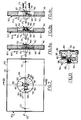
- Figure 1 is a section illustrating a boiler with atmospheric burner, provided with a draft hood which is here arranged in the rear part of said boiler, in accordance with a conventional construction.
- the boiler 1 thus comprises a body 2, in the lower part of which a burner 3 is provided, connected to a manifold 4 for the gas inlet. There is also a hearth 5, above which is provided a battery of exchanger elements 6.
- an upper cover 7 is provided delimiting a confined outlet space 15, said upper cover having a hatch inspection 8, and extending, here backwards, by a draft hood 9 with which it communicates by a lateral opening 12.
- the draft hood 9 is in the form of a rectangular housing, open above the level a nozzle 10 for connection to the chimney, and lower at 11 for the entry of dilution air.
- the path taken by the hot gases is illustrated by continuous arrows starting from the hearth and passing through the exchanger, to exit in the upper part of the draft hood 9.
- This main flow is combined a flow of dilution air penetrating through the lower opening 11 of the draft hood 9.
- Also illustrated by hatched arrows 13 are the combustion air inlets in the lower part of the heating body 2, and by hatched arrows 14 the dilution air inlet at the bottom of the draft hood 9.
- the draft cutter 9 first of all makes it possible to regularize the effect of the variations in the draft of the chimney, and allows a dilution of the fumes by a supply of cold air.
- the draft hood 9 also intervenes in the event of anomalies in the chimney draft conditions, allowing in this case a total or partial overflow of the fumes thereby avoiding affecting the good combustion characteristics of the burner 3.
- the hot gases then exit through the lower opening 11 of the draft hood 9, opening which is normally concerned by the cold dilution air.
- FIGS 2 and 3 illustrate the mounting and operating mode of an overflow safety device usually fitted to an atmospheric burner boiler of the type described above.
- FIG. 2 thus makes it possible to distinguish the control thermostat 50, normally open, and a time relay 51 whose movable member 52 makes it possible to interrupt the line 54 serving for the supply of a gas valve of the burner 53 (the line 55 corresponds to neutral).
- the known overflow safety device thus uses two electrical members linked together, namely a control thermostat 50, and a time relay 51.
- FIG. 3 The operation of this overflow safety device is illustrated in FIG. 3, on which the mode of intervention of said device in the event of an overflow is shown.
- the system In the left part of the diagram, the system is in an operating state corresponding to normal conditions: the control thermostat 50 is open, which corresponds to its rest position, so that the time relay 51 is not supplied.
- the sequence diagram 56 thus corresponds to normal walking; on the diagram giving the variations of the temperature of the control thermostat as a function of time, this results in a temperature curve 56 ′ entirely disposed below a predetermined overflow threshold, for example 60 ° C.
- the control thermostat 50 disposed in the interior space 16 of the draft hood 9, closes suddenly when the threshold of 60 ° C is reached, which has the effect of acting on the relay timed 51 so that the movable member 52 thereof opens the circuit, which causes the burner to shut down: on the sequence diagram, this corresponds to a phase 57 of shutdown of the burner.
- the time relay 51 provides a given time delay, for example 15 min, during which the system cools freely, which corresponds to a segment 57 ′ on the temperature curve. At the end of 15 minutes, the time delay is released, and, if the abnormal conditions have stopped, the burner is automatically restarted if the abnormal conditions still exist, the control thermostat 50 closes again, for a new time delay by l time delay relay intervention 51.
- an overflow safety device associated with the draft hood 9 of a boiler 1 with atmospheric burner 3, comprising a control thermostat 50 used to detect an abnormal rise in temperature corresponding to an anomaly in the draft conditions, and in this case making it possible to quickly cut the electrical supply to the burner 3, as well as a time delay means, generally produced in the form of a time relay 51, authorizing the restarting of boiler after a given waiting time following burner shutdown 3.
- the draft hood 9 of the atmospheric burner boiler is equipped with an overflow safety device 100, in which the control thermostat 150 is arranged against a wall of the draft hood 9 in order to detect the heating of a predetermined area thereof which is highly stressed in the event of overflow, said thermostat acting directly on the electrical supply of the burner 3 when this heating reaches a given threshold; in addition, the delay is ensured by a thermal insulation means 160, surrounding the thermostat 150, said insulation means being disposed against said predetermined area of the wall to slow the cooling, and having a thermal inertia such as the delay thus obtained corresponds at least to the given waiting time.
- the predetermined area of the wall whose temperature is to be detected must be chosen as being a highly stressed area in the event of overflow: we are in fact seeking to have a reaction that is both rapid at an increase in temperature, and reproducible.
- thermoelectric device 100 A fundamental difference is already apparent between the overflow safety device 100 according to the invention, and the prior devices: a single electrical member is used, namely the thermostat 150, the timing function being essentially ensured not by electro-mechanical means, but by purely static thermal insulation means, the operating range of the thermostat and the thermal inertia of the thermal insulation means being also chosen so that the delay obtained corresponds at least to given waiting time that could be obtained using a time relay. It will in particular be advantageous for the thermostat 150 to be a contact thermostat with a wide operating range, for example a thermostat opening at around 60 ° C and closing at around 35 ° C.
- FIG. 5 illustrates the electrical mounting of the overflow safety device according to the invention, which is now extremely simplified, since the control thermostat 150 is the only electrical member inserted on the line 154 leading to the gas valve of the burner 153 (the dotted lines schematize the initial line, and the neutral line is referenced 155).
- the control thermostat 150 when the operating conditions are considered to be normal, that is to say when the temperature detected by the control thermostat 150 remains below a predetermined threshold, for example 60 ° C, the control thermostat 150 is normally closed, which corresponds to a diagram 156 for the running sequence, and a diagram 156 'for the temperature sequence.
- the control thermostat 150 opens and immediately controls burner shutdown, by means of a rapid and direct action (no longer via a time relay) of said thermostat on the electrical supply of said burner.
- the predetermined area of the wall can then cool, the cooling however being slowed down by the thermal insulation means 160, which corresponds to a delay effect produced in a particularly original manner.
- the temperature diagram 157 ′ can thus correspond to the diagram 57 ′ which was obtained with a timed relay, between two extreme points denoted A and B.
- a predetermined low threshold for example 35 ° C.
- control thermostat 150 is preferably a contact thermostat, chosen with a wide range: for example, it is possible to use a thermostat opening at 60 ° C ⁇ 3 ° C, and closing at 35 ° C ⁇ 6 ° C. It goes without saying that the operating range is in any case adapted to the thermal inertia of the thermal insulation means 160.
- FIG. 13 is a section illustrating the structure of a contact thermostat advantageously used, of the normally closed type, thermostat which is normally found on the market.
- the thermostat 150 illustrated here thus comprises a housing 180, closed below by a flange 181 held by a capsule 182.
- the movable member of contact detection consists of a bimetallic disc 183 connected to a transmission axis 184.
- the switching arm 185 fixed by a member 188 to the housing 180, ends with a movable contact 186 normally at rest resting against the associated fixed contact 187.
- thermostat 150 and the thermal insulation means 160 ensuring the desired delay.
- the thermal insulation means 160 is preferably placed outside the rear wall 17 of the draft hood 9, which has the advantage of not disturbing the flow in said draft cutter. It goes without saying, however, that such an arrangement is only an example.
- the thermostat 150 is preferably kept in abutment against the rear wall 17 of the draft hood 9, on the outside of the latter.
- control thermostat 150 can be screwed directly onto the rear wall 17 of the draft hood 9, or even, more simply, and in accordance with another advantageous aspect of the invention, be held in place by the thermal insulation means 160 himself.
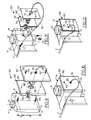
- FIG. 7 makes it possible to distinguish the means of thermal insulation 160, here essentially constituted by an insulating material 161, 162 surrounded by a cover 163 fixed against the rear wall 17 of the draft hood 9.
- FIG. 7 is a view from the interior side , to distinguish the control thermostat 150.
- the insulating material consists of a block of insulation 161 having a central opening 164 to house the thermostat 150, and here a second block of insulation 162 closing said opening central behind said thermostat.
- FIG. 7 makes it possible to distinguish the circular central opening 164 here from the first heat-insulating block 161, making it possible to arrange the control thermostat 150 and the associated connection members: the control thermostat 150 has a contact end 165, a plate 166 having two holes 167 (usually for fixing the thermostat), connection members 168 extending laterally beyond the associated protective insulators 169. There is also a ground wire 170 fixed by an associated bolt 171. FIG. 7 also makes it possible to distinguish the two fixing bolts 172 allowing the assembly of this assembly in the rear part of the draft cutter.
- the second heat-insulating block 162 is compressed in thickness, so as to have a spring effect making it possible to maintain the thermostat 150 against the rear wall 17 of the draft hood 9.
- a heat-insulating block 162 made of glass wool the aerated fibers of which allow significant compression to be obtained in thickness (for example with an initial thickness of 50 mm for a final thickness corresponding to that of the cover, that is to say say about 23 mm).
- the first heat-insulating block 161 has no function to maintain the thermostat to be filled, which makes it possible to choose an economical material, however having sufficient thermal inertia: in practice, we can be satisfied with such a material than rock wool.
- the cover 163 For the system output means, as illustrated in the section of FIG. 8a, provision is made for the cover 163 to carry a cable gland 174, from which a connection cable 175 passes through which the connection wires 168 of the thermostat 150 pass. and the earth connection 170.
- a cable gland 174 is of known type and commonly encountered in trade: it makes it possible to eliminate any risk of untimely tearing of the connection cable, which would ipso facto remove the additional advantage provided by the safety device.
- the 175 cable will also be chosen in accordance with the standards or regulations in force.
- the insulating material 161, 162 preferably constitutes an assembly of rectangular shape, and has a thickness at least equal to 20 mm: the dimensioning illustrated in FIGS. 7 and 8a corresponds to a rectangular panel of 185 mm x 270 mm, with a thickness of 23 mm.
- FIG. 8b illustrates another variant of mounting the control thermostat 150, with the said thermostat being maintained by a spring: a spring 176 is thus distinguished, compressed between the plate 166 of the thermostat and the central inner block of insulation 162 (the central block can in this case be made from an economical material, not necessarily capable of being compressed, such as rock wool).
- the control thermostat 150 can be screwed directly onto the rear wall 17 of the draft cutter 9.
- the bolts 173 inserted by the interior of the cutter draft pass through the holes 167 of the plate 166 of the control thermostat 150, to open normally behind the cover 163.
- this latter assembly is in practice less favorable than the previous assemblies, because of the clearance clearance that the outer covering cover can have.
- the constituent material and the dimensioning of the thermal insulation means 160 will be chosen so as to confer a thermal inertia such that the time delay obtained in association with the thermostat 150 corresponds at least to the waiting time. given, thanks to a controlled slowing down of the cooling of the predetermined area of the wall of the draft hood. It goes without saying that it will always be preferable to arrange to hold as large a temperature as possible for the predetermined area of the wall of the draft hood.
- FIG. 9 provides a better understanding of the mounting mode of the overflow safety device according to the invention.
- control thermostat 150 is not maintained by direct screwing on the rear wall 17 of the draft hood 9, since its maintenance is ensured by the thermal insulation means itself. -even.
- the installation is carried out in a very simple manner, since it suffices to make two holes in the rear wall 17 of the draft cutter 9 to allow the two fixing bolts 173 to be inserted from the rear.
- the distance d between these holes are naturally imposed, and the vertical setting a is determined case by case according to the dimensioning considered.
- the thermostat 150 is also arranged in the vertical plane of symmetry P of the draft hood 9 passing through the axis of the nozzle 10 for connection to the chimney, and is moreover arranged at a level corresponding to an area heavy load in case of overflow.
- the dimension a will be given on an operating manual, so that the thermostat 150 is in fact arranged at a level corresponding to an essentially constant distance from the lower edge of the draft hood 9, for different boilers but whose draft hood is of similar construction.
- the overflow safety device according to the invention thus has a large number of advantages, both technically and commercially.
Landscapes
- Engineering & Computer Science (AREA)
- Physics & Mathematics (AREA)
- Thermal Sciences (AREA)
- Chemical & Material Sciences (AREA)
- Combustion & Propulsion (AREA)
- Mechanical Engineering (AREA)
- General Engineering & Computer Science (AREA)
- Control Of Steam Boilers And Waste-Gas Boilers (AREA)
- Control Of Combustion (AREA)
- Feeding And Controlling Fuel (AREA)
- Regulation And Control Of Combustion (AREA)
Claims (17)
- Abgasüberwachungseinrichtung (100), die der Strömungssicherung (9) eines Heizkessels (1) mit einem atmosphärischen Brenner (3) zugeordnet ist und die einen Kontrollthermostat, der zum Detektieren einer unnormalen Erhöhung der Temperatur dient, die einer Anomalie der Zugbedingungen entspricht, und der es in diesem Fall gestattet, schnell die elektrische Versorgung des Brenners abzuschalten, sowie ein Verzögerungsmittel, welches das Wiederaufnehmen des Betriebs des Kessels nach einer vorgegebenen Wartezeit nach dem Abschalten des Brenners gestattet, umfaßt, wobei der Thermostat (150) an einer Seitenwand (17) der Strömungssicherung (9) angeordnet ist, um das Erwärmen eines vorbestimmten Bereichs derselben, der im Fall des Abgasausttrits stark beansprucht wird, zu detektieren, und dieser Thermostat direkt auf die elektrische Versorgung des Brenners (3) wirkt, wenn diese Erwärmung eine vorgegebene Schwelle erreicht, dadurch gekennzeichnet, daß die Zeitverzögerung durch ein thermisches Isolationsmittel (160) gewährleistet ist, welches den Thermostat (150) umgibt, wobei dieses Isolationsmittel an dem vorbestimmten Bereich der Seitenwand angeordnet ist, um dessen Abkühlung zu verlangsamen, und einen derartigen Wärmeleitwiderstand aufweist, daß die so erhaltene Zeitverzögerung mindestens der vorgegebenen Wartezeit entspricht.
- Uberwachungseinrichtung nach Anspruch 1, dadurch gekennzeichnet, dass der Thermostat (150) ein Kontaktthermostat mit einer weiten Betriebsspanne ist, wobei diese Spanne an den Wärmeleitwiderstand des thermischen Isolationsmittels (160) angepaßt ist.
- Uberwachungseinrichtung nach Anspruch 2, dadurch gekennzeichnet, daß der Thermostat (150) vorzugsweise so gewählt ist, daß er bei ungefähr 60° C öffnet und bei ungefähr 35° C wieder schließt.
- Uberwachungseinrichtung nach einem der Ansprüche 1 bis 3, die einen Strömungssicherung zugeordnet ist, der hinter dem Heizkessel vorgesehen ist, dadurch gekennzeichnet ist, daß der Thermostat (150) an der Rückwand (17) einer Strömungssicherung (9) angeordnet ist.
- Uberwachungseinrichtung nach Anspruch 4, dadurch gekennzeichnet, daß der Thermostat (150) abgestützt an der Rückwand (17) der Strömungssicherung (9) auf dessen Außenseite gehalten ist.
- Uberwachungseinrichtung nach Anspruch 4 oder 5, dadurch gekennzeichnet, daß das thermische Isolationsmittel (160) auf der Außenseite der Rückwand (17) den Strömungssicherung (9) angeordnet ist, um den Fluß in der Strömungssicherung nicht zu stören.
- Uberwarchungseinrichtung nach einem der Ansprüche 4 bis 6, dadurch gekennzeichnet, daß das thermische Isolationsmittel (160) außerdem das Halten des Thermostats (150) an seinem Platz gewährleistet.
- Uberwachungseinrichtung nach einem der Ansprüche 1 bis 7, dadurch gekennzeichnet, dass das thermische Isolationsmittel (160) aus einem Isoliermaterial (161,162) besteht, das von einer Abdeckung (163) umgeben ist, die an der Rückwand (17) der Strömungssicherung (9) befestigt ist.
- Uberwachungseinrichtung nach Anspruch 8, dadurch gekennzeichnet, daß das Isoliermaterial (161,162) sich aus einem Block aus einem Wärmedämmaterial (161), der eine zentrale Öffnung (164) zum Aufnehmen des Thermostats (150) aufweist, und gegebenenfalls einem zweiten Block aus einem Wärmedämmaterial (162) zusammensetzt, der diese zentrale Öffnung hinter dem Thermostat abdichtet.
- Uberwachungseinrichtung nach den Ansprüchen 7 und 9, dadurch gekennzeichnet, daß der zweite Block aus Wärmedämmaterial (162) in der Dicke komprimiert ist, so daß er eine Federkraft ausübt, die das Sichern der Position des Thermostats (150) gestattet.
- Uberwachungseinrichtung nach den Ansprüchen 7 und 9, dadurch gekennzeichnet, daß eine Feder (176) zwischen dem Thermostat (150) und dem zweiten Block aus Wärmedämmaterial (162) angeordnet ist, um das Halten des Thermostats zu gewährleisten.
- Uberwachungseinrichtung nach einem der Ansprüche 9 bis 11, dadurch gekennzeichnet, daß der erste Block aus Wärmedämmaterial (161) aus Gesteinsfasern besteht, während der zweite Block aus Wärmedämmaterial (162) aus Glaswolle besteht.
- Uberwachungseinrichtung nach einem der Ansprüche 8 bis 12, dadurch gekennzeichnet, daß die Abdeckung Anschlußkabel (175) herausführt, durch das die Verbindungsdrähte (168) des Thermostats (150) und ein Masseanschluß (170) laufen.
- Uberwachungseinrichtung nach einem der Ansprüche 8 bis 13, dadurch gekennzeichnet, daß das isolierende Material (161,162) eine rechteckige Form besitzt und eine Dicke von mindestens 20 mm aufweist.
- Uberwachungseinrichtung nach einem der Ansprüche 1 bis 14, dadurch gekennzeichnet, daß der Thermostat (150) in der vertikalen Symmetrieebene (P) der Strömungssicherung (9) liegt, die durch die Achse der Verbindungsdüse (10) zum Abzug geht.
- Uberwachungseinrichtung nach Anspruch 15, dadurch gekennzeichnet, daß der Thermostat (150) auf einem Niveau angeordnet ist, das einem im wesentlichen konstanten Abstand von der Unterkante der Strömungssicherung (9) für verschiedene Heizkessel, deren Zugbegrenzer aber von ähnlicher Konstruktion sind, entspricht.
- Uberwachungseinrichtung nach einem der Ansprüche 1 bis 16, dadurch gekennzeichnet, daß der Thermostat (150) von der Art ist, die im Normalfall geschlossen ist.
Priority Applications (1)
| Application Number | Priority Date | Filing Date | Title |
|---|---|---|---|
| AT90402096T ATE94976T1 (de) | 1989-07-21 | 1990-07-20 | Rueckstromsicherung fuer die zugunterbrechung eines kessels mit atmosphaerischem brenner. |
Applications Claiming Priority (2)
| Application Number | Priority Date | Filing Date | Title |
|---|---|---|---|
| FR8909862 | 1989-07-21 | ||
| FR8909862A FR2650058B1 (fr) | 1989-07-21 | 1989-07-21 | Dispositif de securite de debordement associe au coupe-tirage d'une chaudiere a bruleur atmospherique |
Publications (2)
| Publication Number | Publication Date |
|---|---|
| EP0409738A1 EP0409738A1 (de) | 1991-01-23 |
| EP0409738B1 true EP0409738B1 (de) | 1993-09-22 |
Family
ID=9384024
Family Applications (1)
| Application Number | Title | Priority Date | Filing Date |
|---|---|---|---|
| EP90402096A Expired - Lifetime EP0409738B1 (de) | 1989-07-21 | 1990-07-20 | Rückstromsicherung für die Zugunterbrechung eines Kessels mit atmosphärischem Brenner |
Country Status (4)
| Country | Link |
|---|---|
| EP (1) | EP0409738B1 (de) |
| AT (1) | ATE94976T1 (de) |
| DE (2) | DE69003481T4 (de) |
| FR (1) | FR2650058B1 (de) |
Family Cites Families (1)
| Publication number | Priority date | Publication date | Assignee | Title |
|---|---|---|---|---|
| DE3137740A1 (de) * | 1981-09-23 | 1983-04-07 | Stiebel Eltron Gmbh & Co Kg, 3450 Holzminden | Gasheizgeraet mit atmosphaerischem brenner |
-
1989
- 1989-07-21 FR FR8909862A patent/FR2650058B1/fr not_active Expired - Fee Related
-
1990
- 1990-07-20 DE DE69003481T patent/DE69003481T4/de not_active Expired - Lifetime
- 1990-07-20 EP EP90402096A patent/EP0409738B1/de not_active Expired - Lifetime
- 1990-07-20 DE DE90402096A patent/DE69003481D1/de not_active Expired - Fee Related
- 1990-07-20 AT AT90402096T patent/ATE94976T1/de active
Also Published As
| Publication number | Publication date |
|---|---|
| FR2650058B1 (fr) | 1991-11-08 |
| DE69003481T2 (de) | 1994-07-28 |
| FR2650058A1 (fr) | 1991-01-25 |
| ATE94976T1 (de) | 1993-10-15 |
| DE69003481T4 (de) | 1994-10-20 |
| DE69003481D1 (de) | 1993-10-28 |
| EP0409738A1 (de) | 1991-01-23 |
Similar Documents
| Publication | Publication Date | Title |
|---|---|---|
| EP0277888B1 (de) | Gasofen mit Dampferzeuger | |
| FR2595134A1 (fr) | Bruleur a gaz a soufflage d'air force pour un poele a bois | |
| FR2536507A1 (fr) | Procede pour faire fonctionner un bruleur a gazeification pour carburant liquide, bruleur a gazeification et dispositif de commande pour la mise en oeuvre dudit procede | |
| EP1845311B1 (de) | Vorrichtung zur temperaturmessung in einem backofen und backofen, der eine solche temperaturmessvorrichtung umfasst | |
| EP1291580A1 (de) | Gasgerät mit Brenner im niedrigen Teil und mit Sicherheitsmitteln, und die Verwendung als Wassererhitzer | |
| EP0409738B1 (de) | Rückstromsicherung für die Zugunterbrechung eines Kessels mit atmosphärischem Brenner | |
| FR2480908A1 (fr) | Foyer muni d'un limiteur de tirage et d'un systeme de ventilation | |
| FR2643443A1 (fr) | Dispositif de recuperation de chaleur pour cheminee a atre | |
| FR2610703A1 (fr) | Dispositif de regulation et de commande pour un four de cuisson menager chauffe au gaz avec bruleur de gril supplementaire | |
| FR2713748A1 (fr) | Générateur de chaleur utilisant des combustibles solides et muni d'un dispositif d'allumage. | |
| EP0663991B1 (de) | Vorrichtung und anlage zur abfallverbrennung | |
| FR2964726A1 (fr) | Equipement pour chaudiere comprenant au moins une sonde de securite mecanique | |
| EP0790467A1 (de) | Sicherheitsvorrichtung an Gasheizungen und Gaskochern | |
| EP0135639B1 (de) | Vorrichtung zur Verbesserung der Betriebscharakteristiken einer Heizanlage mit Tauchbrenner | |
| EP0011568B1 (de) | Verbesserung von luftdichten Haushaltsgasapparaten mit erzwungenem Zug | |
| EP0432020B1 (de) | Gasdichter Kessel mit Zwangsabzug unter Verwendung eines Thermokontakts | |
| CA1233082A (fr) | Procede et installation permettant d'ameliorer les caracteristiques de fonctionnement d'une installation de chauffage a combustion submergee | |
| EP1779039A1 (de) | Mikrowellenzündungsverfahren und vorrichtung für kochgeräte mit festem brennstoff | |
| FR2476277A1 (fr) | Cheminee d'interieur pour feu de bois | |
| EP0524853B1 (de) | Sicherheitsvorrichtung zum Detektieren von anormalem Zug für einen Gaskessel mit einem Rauchgaskanal mit natürlichem Zug | |
| EP0984224B1 (de) | Anzeigesystem eines Brenners | |
| FR2468835A2 (fr) | Installation d'evacuation des fumees d'une chaudiere, notamment d'une chaudiere a bruleurs a marche intermittente | |
| FR2707105A1 (fr) | Dispositif de ventilation pour récupérateur de chaleur de cheminée à foyer ouvert ou à foyer fermé. | |
| CH619036A5 (en) | Ventilation device for a combustion chamber of a heating installation | |
| BE419662A (de) |
Legal Events
| Date | Code | Title | Description |
|---|---|---|---|
| PUAI | Public reference made under article 153(3) epc to a published international application that has entered the european phase |
Free format text: ORIGINAL CODE: 0009012 |
|
| AK | Designated contracting states |
Kind code of ref document: A1 Designated state(s): AT BE CH DE DK ES FR GB GR IT LI LU NL SE |
|
| 17P | Request for examination filed |
Effective date: 19910708 |
|
| 17Q | First examination report despatched |
Effective date: 19911119 |
|
| GRAA | (expected) grant |
Free format text: ORIGINAL CODE: 0009210 |
|
| AK | Designated contracting states |
Kind code of ref document: B1 Designated state(s): AT BE CH DE DK ES FR GB GR IT LI LU NL SE |
|
| PG25 | Lapsed in a contracting state [announced via postgrant information from national office to epo] |
Ref country code: IT Free format text: LAPSE BECAUSE OF FAILURE TO SUBMIT A TRANSLATION OF THE DESCRIPTION OR TO PAY THE FEE WITHIN THE PRE;WARNING: LAPSES OF ITALIAN PATENTS WITH EFFECTIVE DATE BEFORE 2007 MAY HAVE OCCURRED AT ANY TIME BEFORE 2007. THE CORRECT EFFECTIVE DATE MAY BE DIFFERENT FROM THE ONE RECORDED.SCRIBED TIME-LIMIT Effective date: 19930922 Ref country code: ES Free format text: THE PATENT HAS BEEN ANNULLED BY A DECISION OF A NATIONAL AUTHORITY Effective date: 19930922 Ref country code: AT Effective date: 19930922 Ref country code: GR Free format text: LAPSE BECAUSE OF FAILURE TO SUBMIT A TRANSLATION OF THE DESCRIPTION OR TO PAY THE FEE WITHIN THE PRESCRIBED TIME-LIMIT Effective date: 19930922 Ref country code: DK Effective date: 19930922 Ref country code: SE Effective date: 19930922 |
|
| REF | Corresponds to: |
Ref document number: 94976 Country of ref document: AT Date of ref document: 19931015 Kind code of ref document: T |
|
| REF | Corresponds to: |
Ref document number: 69003481 Country of ref document: DE Date of ref document: 19931028 |
|
| GBT | Gb: translation of ep patent filed (gb section 77(6)(a)/1977) |
Effective date: 19931006 |
|
| PLBE | No opposition filed within time limit |
Free format text: ORIGINAL CODE: 0009261 |
|
| STAA | Information on the status of an ep patent application or granted ep patent |
Free format text: STATUS: NO OPPOSITION FILED WITHIN TIME LIMIT |
|
| PG25 | Lapsed in a contracting state [announced via postgrant information from national office to epo] |
Ref country code: CH Effective date: 19940731 Ref country code: LI Effective date: 19940731 Ref country code: LU Free format text: LAPSE BECAUSE OF NON-PAYMENT OF DUE FEES Effective date: 19940731 |
|
| 26N | No opposition filed | ||
| REG | Reference to a national code |
Ref country code: CH Ref legal event code: PL |
|
| REG | Reference to a national code |
Ref country code: GB Ref legal event code: IF02 |
|
| PGFP | Annual fee paid to national office [announced via postgrant information from national office to epo] |
Ref country code: FR Payment date: 20020719 Year of fee payment: 13 |
|
| PGFP | Annual fee paid to national office [announced via postgrant information from national office to epo] |
Ref country code: NL Payment date: 20030619 Year of fee payment: 14 |
|
| PGFP | Annual fee paid to national office [announced via postgrant information from national office to epo] |
Ref country code: DE Payment date: 20030708 Year of fee payment: 14 |
|
| PGFP | Annual fee paid to national office [announced via postgrant information from national office to epo] |
Ref country code: GB Payment date: 20030715 Year of fee payment: 14 |
|
| PGFP | Annual fee paid to national office [announced via postgrant information from national office to epo] |
Ref country code: BE Payment date: 20030812 Year of fee payment: 14 |
|
| PG25 | Lapsed in a contracting state [announced via postgrant information from national office to epo] |
Ref country code: FR Free format text: LAPSE BECAUSE OF NON-PAYMENT OF DUE FEES Effective date: 20040331 |
|
| REG | Reference to a national code |
Ref country code: FR Ref legal event code: ST |
|
| PG25 | Lapsed in a contracting state [announced via postgrant information from national office to epo] |
Ref country code: GB Free format text: LAPSE BECAUSE OF NON-PAYMENT OF DUE FEES Effective date: 20040720 |
|
| PG25 | Lapsed in a contracting state [announced via postgrant information from national office to epo] |
Ref country code: BE Free format text: LAPSE BECAUSE OF NON-PAYMENT OF DUE FEES Effective date: 20040731 |
|
| BERE | Be: lapsed |
Owner name: *CIE INTERNATIONALE DU CHAUFFAGE Effective date: 20040731 |
|
| PG25 | Lapsed in a contracting state [announced via postgrant information from national office to epo] |
Ref country code: NL Free format text: LAPSE BECAUSE OF NON-PAYMENT OF DUE FEES Effective date: 20050201 Ref country code: DE Free format text: LAPSE BECAUSE OF NON-PAYMENT OF DUE FEES Effective date: 20050201 |
|
| GBPC | Gb: european patent ceased through non-payment of renewal fee |
Effective date: 20040720 |
|
| NLV4 | Nl: lapsed or anulled due to non-payment of the annual fee |
Effective date: 20050201 |
|
| BERE | Be: lapsed |
Owner name: *CIE INTERNATIONALE DU CHAUFFAGE Effective date: 20040731 |