EP0410020A1 - Procédé et dispositif pour le nettoyage automatique des pots et/ou du limiteur de ballon d'une broche à retordre à double torsion d'un métier à retordre à double-torsion - Google Patents
Procédé et dispositif pour le nettoyage automatique des pots et/ou du limiteur de ballon d'une broche à retordre à double torsion d'un métier à retordre à double-torsion Download PDFInfo
- Publication number
- EP0410020A1 EP0410020A1 EP89113550A EP89113550A EP0410020A1 EP 0410020 A1 EP0410020 A1 EP 0410020A1 EP 89113550 A EP89113550 A EP 89113550A EP 89113550 A EP89113550 A EP 89113550A EP 0410020 A1 EP0410020 A1 EP 0410020A1
- Authority
- EP
- European Patent Office
- Prior art keywords
- bobbin
- double
- cleaning
- cleaning device
- spindle
- Prior art date
- Legal status (The legal status is an assumption and is not a legal conclusion. Google has not performed a legal analysis and makes no representation as to the accuracy of the status listed.)
- Granted
Links
- 238000004140 cleaning Methods 0.000 title claims abstract description 77
- 238000000034 method Methods 0.000 title abstract description 9
- 238000012423 maintenance Methods 0.000 claims description 33
- 230000006835 compression Effects 0.000 claims description 5
- 238000007906 compression Methods 0.000 claims description 5
- 238000009825 accumulation Methods 0.000 claims description 4
- 239000000463 material Substances 0.000 claims description 4
- 238000007667 floating Methods 0.000 claims description 3
- 238000011017 operating method Methods 0.000 claims 3
- 239000000428 dust Substances 0.000 abstract description 6
- 239000002245 particle Substances 0.000 abstract description 3
- 230000001681 protective effect Effects 0.000 description 6
- 238000003860 storage Methods 0.000 description 4
- 238000007664 blowing Methods 0.000 description 2
- 238000010276 construction Methods 0.000 description 2
- 238000011109 contamination Methods 0.000 description 2
- 230000000694 effects Effects 0.000 description 1
- 238000005516 engineering process Methods 0.000 description 1
- 238000000605 extraction Methods 0.000 description 1
- 230000007774 longterm Effects 0.000 description 1
- 238000010327 methods by industry Methods 0.000 description 1
- 238000003825 pressing Methods 0.000 description 1
- 238000007789 sealing Methods 0.000 description 1
- 238000009987 spinning Methods 0.000 description 1
Images




Classifications
-
- D—TEXTILES; PAPER
- D01—NATURAL OR MAN-MADE THREADS OR FIBRES; SPINNING
- D01H—SPINNING OR TWISTING
- D01H4/00—Open-end spinning machines or arrangements for imparting twist to independently moving fibres separated from slivers; Piecing arrangements therefor; Covering endless core threads with fibres by open-end spinning techniques
- D01H4/04—Open-end spinning machines or arrangements for imparting twist to independently moving fibres separated from slivers; Piecing arrangements therefor; Covering endless core threads with fibres by open-end spinning techniques imparting twist by contact of fibres with a running surface
- D01H4/22—Cleaning of running surfaces
-
- D—TEXTILES; PAPER
- D01—NATURAL OR MAN-MADE THREADS OR FIBRES; SPINNING
- D01H—SPINNING OR TWISTING
- D01H11/00—Arrangements for confining or removing dust, fly or the like
-
- D—TEXTILES; PAPER
- D01—NATURAL OR MAN-MADE THREADS OR FIBRES; SPINNING
- D01H—SPINNING OR TWISTING
- D01H13/00—Other common constructional features, details or accessories
- D01H13/005—Service carriages travelling along the machines
Definitions
- Cross-wound bobbins with a long thread length are produced on double-wire twisting machines.
- the operating times for a full untwisted bobbin are between 4 and 44 hours and more.
- Double wire twisting machine associated work processes inevitable dust and sometimes contamination of the double wire twisting machine. It is therefore common to equip such and other machines, e.g. spinning machines, with traveling blowing devices that pass every working or twisting point at certain intervals and keep certain areas of the machine free of excessive dust or contamination by blowing or suction flows. Although these measures are helpful, they are usually inadequate in the case of double-wire twisting spindles because the thread balloon resulting from the double-wire twisting cannot reach certain machine areas. This is particularly true for the spindle area and especially for the coil pot and the balloon limiter, but also for the spindle rotor itself.
- the invention has for its object to provide measures both in terms of process engineering and design, in particular in connection with the replacement of a supply spool, the particularly vulnerable machine areas, namely coil pot and / or balloon limiter and / or spindle rotor in an automa cleaned procedure.
- the measures according to claims 1 and / or 2 serve in terms of process technology and the measures according to claims 4 and / or 10 in constructive terms.
- the invention also relates to the cleaning devices themselves without being assigned to an automatic maintenance machine.
- FIG. 1 shows a detail of a double-wire twisting machine A, an automatic maintenance machine B which can be moved along the double-wire twisting machine on lower and upper rails 1 and 2, and a hanging conveyor device C.
- the overhead conveyor device C comprises a top rail 3, in which a conveyor chain or a conveyor belt is guided, to which or on which bobbin hanging holders 4 for bobbin adapters or bobbin transport adapters 5, which hang down at regular intervals, are fastened.
- the bobbin hanging holder 4 and the bobbin adapter 5 are designed in a known manner so that when a bobbin adapter 5 is started up, the bobbin adapter is gripped and held by the bobbin hanging holder, while the bobbin adapter 5 is released by the bobbin hanging holder 4 during the subsequent raising and lowering thereof.
- FIG. 1 shows in the area of the top rail 3 on the left side six bobbin adapters 5 each equipped with two fully wound cross-wound bobbins 6, which are to be transferred to the individual twisting points of the double-wire twisting machine 1 by means of the maintenance machine B, and two with empty sleeves 6 on the right 'Equipped coil adapter 5, from the maintenance machine B individually from twisting the double wire-thread A are removed and transferred to a bobbin hanger holder 4.
- the double-wire twisting machine A comprises several working or twisting stations with the usual known elements such as (not shown) spindle in the lower area, balloon limiter 7, bobbin pot 8, thread inlet 9, balloon thread guide 10, deflection elements 11 for controlling the thread opening tension, advance line 12, traversing thread guide 13 and the cross-wound spool or take-up spool 15 driven by a friction roller 14.
- a conveyor belt 16 for the removal of fully wound cross-wound bobbins 15.
- Above each cross-wound thread or The package 15 has a sleeve magazine 17 for empty take-up tubes 18.
- the maintenance machine B patrols in front of the double-wire twisting machine A or the individual twisting points otherwise not shown unit, on the one hand to insert bobbin adapters equipped with full supply bobbins into the individual twisting points or double-wire spindles and on the other hand to remove bobbin adapters equipped with empty or almost empty tubes from the double-wire spindles.
- the maintenance machine B has a cabinet-shaped housing 101, the front wall of which is provided with a guide slot 102 for the pivotable cross arm 103 which carries a holding mandrel 100.
- the holding mandrels 100 serve as transport elements for coil adapters between the overhead conveyor device C and the lower area of the maintenance machine B.
- FIG. 3 additionally shows the bobbin and the usual thread storage disk 19 of a double-wire twisting spindle.
- the spindle whorl 31 of the double-wire spindle is driven by means of a tangential drive belt 33 which is pressed against the spindle whirl 31 by a belt pressure roller 32.
- a foot lever 34 assigned to each individual spindle serves to actuate a spindle brake (not shown), and this foot lever 34 also serves to actuate the compressed air nozzle 30 in order to build up a suction air flow in the spindle hollow axis in a known manner for the purpose of threading the thread through the spindle.
- Fig. 3 also shows partial areas of the maintenance machine B patrolling in front of the double-wire twisting machine along the rails 1 and 2, which has an actuating lever 35, by pressing it down in the direction of arrow f1 at the given moment the foot lever 34 can be actuated to stop the individual spindles .
- Fig. 3 shows just above the foot lever 34 two rollers 36 which are guided along a guide surface 1.1 of the lower rail 1.
- the first cleaning device 23 shown in FIG. 2 is used to clean the bobbin 8 of a double-wire twisting spindle.
- This first cleaning device 23 contains a swivel arm 40 which is mounted in the maintenance machine B and can be moved up and down and pivoted about a vertical axis, through the inside of which one does not become one Suction air line 40.1 leading shown suction air source and a compressed air line 40.2 leading to a compressed air source, not shown, run.
- a head piece 40.3 into which a suction mouthpiece 41 is inserted, which is directed vertically downwards and is connected to the suction air line 40.1.
- the lower end of the tubular suction mouthpiece 41 widens in a funnel shape.
- a working shaft 42 of an electric motor 43 placed on the head piece 40.3 runs coaxially through the suction mouthpiece 41.
- the lower end of the working shaft 42 carries a hub part 44, to which vertically extending brush strips 46 are fastened by means of radially directed, preferably pivotable arms 45.
- the tubular suction mouthpiece 41 is surrounded by an annular cylinder 40.4 adjoining the headpiece 40.3, into which an actuator in the form of an annular piston 47 is inserted, which is sealingly guided in the annular cylinder 40.4 by means of sealing rings 48, 49.
- Double-armed gripper levers 52 are pivotally mounted on the outside of the suction mouthpiece 41 by means of tabs 51.
- Each gripper lever 52 has an upper lever arm 52.1, the end of which bears against the underside of the annular piston 47, and a lower lever arm 52.2, the lower free end of which is designed as a gripping projection 52.3 which is used to grip the bobbin 8 against the upper one Edge of the same can be brought to the plant.
- the cleaning device 23 is pivoted out of the maintenance machine into a central position above the spindle axis of the double-wire twisting spindle.
- the cleaning device 23 is then lowered until the gripping projections 52.3 come to bear against the upper edge of the bobbin 8.
- the annular piston 47 is lowered by supplying compressed air into the pressure chamber 50, as a result of which the lower free lever arms 52.2 are pivoted inwards, so that the bobbin is firmly gripped and secured against rotation.
- the electric motor 43 is started, whereby the brush strips 46 inserted into the protective pot are rotated and guided along the inner wall of the protective pot 8.
- the suction air line 40.1 is connected to the suction air source, so that air loaded with dirt parts and dust particles is sucked out of the bobbin 8 and conducted away through the suction mouthpiece 41.
- the brush strips 46 have a length corresponding to the height of the coil pot 8, it being possible for radial, downwardly directed brush strips to be attached to the bottom of the axis 42 or the hub part 44 for cleaning the coil pot bottom.
- the maintenance machine B can be one which, in addition to the cleaning device 23 described above and a possibly further cleaning device 24, which is still to be described, also comprises additional maintenance and handling elements with which a coil or sleeve exchange can be carried out.
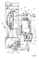
- FIG. 3 and 4 show an arrangement which, in addition to a first cleaning device 23, in particular described in connection with FIG. 2, comprises a further second cleaning device 24, which is provided for cleaning or cleaning the balloon limiter 7.
- FIG 3 shows the state in which the bobbin 8 is lifted out of the balloon limiter 7 by the first cleaning device 23 in the direction of the arrow f2, in order then to be pivoted into the interior of the maintenance machine B in the direction of the arrow f3.
- the second cleaning device 24 which is fastened to a swivel arm 54, is then pivoted out of the maintenance machine B in the direction of the arrow f4 over the spindle to be serviced or cleaned.
- This second cleaning device 24 also contains a drive motor 55 for driving a shaft 56, which carries a hub 57, to which vertically arranged brush strips 58 for the inner wall of the balloon limiter 7 are fastened.
- the extraction of air laden with dirt or dust particles can be carried out by means of a suction nozzle 59 which can be produced from the maintenance machine B on the thread storage disk 19, or by means of a suction device, as is essentially described in connection with FIG. 2 for the first suction device 23.
- 4 also shows an additional suction nozzle 60 in the interior of the maintenance machine B in order to clean the bobbin 8 inside the goods machine B to extract air laden with dust or dirt.
- This suction nozzle 60 can be used in addition or as a replacement for the suction device described in connection with FIG.
- FIG. 6 shows the special construction of a cleaning device according to the invention and / or according to the invention used in connection with a maintenance machine.
- the cleaning device shown in FIG. 6 can be used both as a cleaning device for the coil pot 8 or as a cleaning device for a balloon limiter 7, as is expressed in FIG. 6.
- FIG. 6 it is assumed that it is the cleaning device 24 which has a driven shaft 56 with a hub 57 fastened to the shaft end, to which the brush strips 58 are fastened.
- the hub 57 is provided on its underside with a bearing block 61 which can be plugged onto the upper part of the spindle axis 62.
- the individual brush strip 58 is movably attached to the hub 57 by means of a double-armed pivot lever 63.
- Each pivot lever 63 is pivotable about a horizontal axis, which is mounted such that the pivot lever, relative to the spindle axis, can be pivoted in a radial plane is.
- One lower lever arm 63.1 is pressed outwards by means of a compression spring 64, while the brush strip 58 is articulated on the other upper lever arm 52.2, essentially in the middle of the length of the brush strip.
- each brush strip 58 At the lower end of each brush strip 58, a material accumulation 58.1 is attached or provided. This accumulation of material 58.1 has the effect that when the shaft 56 and thus the hub body 57 are rotated, the lower end of each brush strip 58 is first moved outward under the influence of centrifugal force, so that the lower bristles of each brush strip are first against the inner wall of the balloon limiter come to rest and thereby move down into the gap between the balloon limiter and the usual overflow plate 19.1 of the thread storage disk 19. At higher speed, the brush strip 58 is then moved outwards over its entire length, so that cleaning takes place over the entire balloon limiter height.
- the bearing block 61 is inside the hub body 57 floating in the axial direction and is supported relative to the hub body by means of an axially arranged compression spring 64, so that in the direction of the double arrow f5, sufficient axial movement space between the spindle axis 62 and the shaft 56 is possible to place the bearing block 61 on the spindle axis 62 Switch off damage in the area of the spindle axis 62 or the bearing of the spindle axis 62.
- suction systems can be assigned to a system according to FIG. 6 either in the form of a central suction mouthpiece 41 or in the form of suction nozzles positioned laterally, roughly comparable to the suction nozzle 59 in FIG. 4.
- the cleaning device according to the invention can also be used independently of a maintenance machine, optionally with an integrated drive motor or with a drive motor that can be coupled to it.
Landscapes
- Engineering & Computer Science (AREA)
- Mechanical Engineering (AREA)
- Textile Engineering (AREA)
- Spinning Or Twisting Of Yarns (AREA)
Priority Applications (7)
| Application Number | Priority Date | Filing Date | Title |
|---|---|---|---|
| DE58908650T DE58908650D1 (de) | 1989-07-24 | 1989-07-24 | Betriebsverfahren und Vorrichtung zum automatisierten Reinigen von Spulentöpfen und gegebenenfalls Ballonbegrenzern der Doppeldraht-Zwirnspindel einer Doppeldraht-Zwirnmaschine. |
| EP89113550A EP0410020B1 (fr) | 1989-07-24 | 1989-07-24 | Procédé et dispositif pour le nettoyage automatique des pots et/ou du limiteur de ballon d'une broche à retordre à double torsion d'un métier à retordre à double-torsion |
| US07/554,734 US5095692A (en) | 1989-07-24 | 1990-07-18 | Operating method and apparatus for automatically cleaning spindle assemblies of a two-for-one twister yarn processing machine |
| DD342973A DD300113A5 (de) | 1989-07-24 | 1990-07-20 | Betriebsverfahren und Vorrichtung zum automatischen Reinigen von Spulenköpfen und gegebenenfalls Ballonbegrenzern der Doppeldraht-Zwirnspindeln einer Doppeldraht-Zwirnmaschine |
| JP2193187A JPH0359125A (ja) | 1989-07-24 | 1990-07-23 | ダブルツイスタ用スピンドルの保護ポットとバルーン制限器の自動清掃方法並びに装置 |
| CS903683A CS368390A2 (en) | 1989-07-24 | 1990-07-24 | Method and device for automatized cleanin of bobbin cans and, if need be,of double twisting spindles' balloon separators with two-for-one twister |
| US07/764,810 US5245818A (en) | 1989-07-24 | 1991-09-24 | Method for cleaning yarn supply package protective pots and balloon limiters of spindle assemblies of two-for-one twister yarn processing machines |
Applications Claiming Priority (1)
| Application Number | Priority Date | Filing Date | Title |
|---|---|---|---|
| EP89113550A EP0410020B1 (fr) | 1989-07-24 | 1989-07-24 | Procédé et dispositif pour le nettoyage automatique des pots et/ou du limiteur de ballon d'une broche à retordre à double torsion d'un métier à retordre à double-torsion |
Publications (2)
| Publication Number | Publication Date |
|---|---|
| EP0410020A1 true EP0410020A1 (fr) | 1991-01-30 |
| EP0410020B1 EP0410020B1 (fr) | 1994-11-17 |
Family
ID=8201673
Family Applications (1)
| Application Number | Title | Priority Date | Filing Date |
|---|---|---|---|
| EP89113550A Expired - Lifetime EP0410020B1 (fr) | 1989-07-24 | 1989-07-24 | Procédé et dispositif pour le nettoyage automatique des pots et/ou du limiteur de ballon d'une broche à retordre à double torsion d'un métier à retordre à double-torsion |
Country Status (6)
| Country | Link |
|---|---|
| US (1) | US5095692A (fr) |
| EP (1) | EP0410020B1 (fr) |
| JP (1) | JPH0359125A (fr) |
| CS (1) | CS368390A2 (fr) |
| DD (1) | DD300113A5 (fr) |
| DE (1) | DE58908650D1 (fr) |
Cited By (4)
| Publication number | Priority date | Publication date | Assignee | Title |
|---|---|---|---|---|
| EP0588632A1 (fr) * | 1992-09-17 | 1994-03-23 | Ngk Insulators, Ltd. | Piles à combustible à oxides solides, procédé pour fabrication de films solides d'électrolyte et procédé pour fabrication des piles à combustible à oxides solides |
| DE4244199A1 (de) * | 1992-12-24 | 1994-06-30 | Schlafhorst & Co W | Vorrichtung zum Reinigen von Außen- und Innenkonturen von Teilen von Spinnaggregaten an einer Spinnmaschine |
| EP0857799A1 (fr) * | 1997-02-05 | 1998-08-12 | SANT'ANDREA NOVARA S.p.A. | Machine de peignage rectiligne avec un système amélioré pour mettre en place et enlever la brosse cylindrique |
| CN110578193A (zh) * | 2019-10-10 | 2019-12-17 | 海盐浦洋丝业有限公司 | 一种倍捻机用纱线清洗装置 |
Families Citing this family (4)
| Publication number | Priority date | Publication date | Assignee | Title |
|---|---|---|---|---|
| US5526634A (en) * | 1990-10-23 | 1996-06-18 | Murata Kikai Kabushiki Kaisha | Robot device for piled-package type double twister |
| JP4805254B2 (ja) * | 2004-04-20 | 2011-11-02 | ビジュアルソニックス インコーポレイテッド | 配列された超音波トランスデューサ |
| US7901358B2 (en) | 2005-11-02 | 2011-03-08 | Visualsonics Inc. | High frequency array ultrasound system |
| CN109137168A (zh) * | 2018-10-29 | 2019-01-04 | 沈阳宏大纺织机械有限责任公司 | 一种换筒滑板 |
Citations (3)
| Publication number | Priority date | Publication date | Assignee | Title |
|---|---|---|---|---|
| CH471911A (de) * | 1966-03-14 | 1969-04-30 | Leesona Corp | Verfahren zum Einfädeln in einen Ringläufer einer Textilmaschine, Mittel zur Ausführung des Verfahrens und Anwendung des Verfahrens |
| DE2658441A1 (de) * | 1976-12-23 | 1978-06-29 | Fritz Stahlecker | Offenend-spinnmaschine mit wenigstens einer verfahrbaren wartungseinrichtung |
| DE3824998A1 (de) * | 1987-07-22 | 1989-02-09 | Murata Machinery Ltd | Doppeldrahtzwirnmaschine |
Family Cites Families (7)
| Publication number | Priority date | Publication date | Assignee | Title |
|---|---|---|---|---|
| DE1933930C3 (de) * | 1969-07-04 | 1982-02-11 | Wilhelm Stahlecker Gmbh, 7341 Reichenbach | Offenend-Spinnmaschine mit mehreren Spinnaggregaten |
| US4125991A (en) * | 1976-06-29 | 1978-11-21 | Hans Stahlecker | Mobile servicing device for an open end spinning frame |
| DE2648621C3 (de) * | 1976-10-27 | 1981-11-26 | Palitex Project-Company Gmbh, 4150 Krefeld | Doppeldraht-Zwirnmaschine |
| DE2726229C3 (de) * | 1977-06-10 | 1980-05-14 | Palitex Project-Company Gmbh, 4150 Krefeld | Spinn- oder Zwirnmaschine, insbesondere Doppeldrahtspinn- oder Doppeldrahtzwirnmaschine |
| US4133168A (en) * | 1978-02-21 | 1979-01-09 | Automatic Material Handling, Inc. | Apparatus for removing yarn wraps from spindles |
| DE3313926A1 (de) * | 1983-04-16 | 1984-10-18 | Stahlecker, Fritz, 7347 Bad Überkingen | Oe-rotorspinnmaschine mit einer in die offenen seiten der spinnrotoren einfuehrbaren reinigungseinrichtung |
| IT1222118B (it) * | 1987-07-24 | 1990-08-31 | Savio Spa | Aletta dipanatrice rotante attorno ad un perno sospeso sopra il fuso a doppia torsione per lo svolgimento di rocche sovrapposte |
-
1989
- 1989-07-24 DE DE58908650T patent/DE58908650D1/de not_active Expired - Fee Related
- 1989-07-24 EP EP89113550A patent/EP0410020B1/fr not_active Expired - Lifetime
-
1990
- 1990-07-18 US US07/554,734 patent/US5095692A/en not_active Expired - Fee Related
- 1990-07-20 DD DD342973A patent/DD300113A5/de unknown
- 1990-07-23 JP JP2193187A patent/JPH0359125A/ja active Pending
- 1990-07-24 CS CS903683A patent/CS368390A2/cs unknown
Patent Citations (3)
| Publication number | Priority date | Publication date | Assignee | Title |
|---|---|---|---|---|
| CH471911A (de) * | 1966-03-14 | 1969-04-30 | Leesona Corp | Verfahren zum Einfädeln in einen Ringläufer einer Textilmaschine, Mittel zur Ausführung des Verfahrens und Anwendung des Verfahrens |
| DE2658441A1 (de) * | 1976-12-23 | 1978-06-29 | Fritz Stahlecker | Offenend-spinnmaschine mit wenigstens einer verfahrbaren wartungseinrichtung |
| DE3824998A1 (de) * | 1987-07-22 | 1989-02-09 | Murata Machinery Ltd | Doppeldrahtzwirnmaschine |
Cited By (4)
| Publication number | Priority date | Publication date | Assignee | Title |
|---|---|---|---|---|
| EP0588632A1 (fr) * | 1992-09-17 | 1994-03-23 | Ngk Insulators, Ltd. | Piles à combustible à oxides solides, procédé pour fabrication de films solides d'électrolyte et procédé pour fabrication des piles à combustible à oxides solides |
| DE4244199A1 (de) * | 1992-12-24 | 1994-06-30 | Schlafhorst & Co W | Vorrichtung zum Reinigen von Außen- und Innenkonturen von Teilen von Spinnaggregaten an einer Spinnmaschine |
| EP0857799A1 (fr) * | 1997-02-05 | 1998-08-12 | SANT'ANDREA NOVARA S.p.A. | Machine de peignage rectiligne avec un système amélioré pour mettre en place et enlever la brosse cylindrique |
| CN110578193A (zh) * | 2019-10-10 | 2019-12-17 | 海盐浦洋丝业有限公司 | 一种倍捻机用纱线清洗装置 |
Also Published As
| Publication number | Publication date |
|---|---|
| DD300113A5 (de) | 1992-05-21 |
| US5095692A (en) | 1992-03-17 |
| JPH0359125A (ja) | 1991-03-14 |
| DE58908650D1 (de) | 1994-12-22 |
| EP0410020B1 (fr) | 1994-11-17 |
| CS368390A2 (en) | 1991-11-12 |
Similar Documents
| Publication | Publication Date | Title |
|---|---|---|
| EP0026471B1 (fr) | Dispositif de changement de bobines pour machines textiles | |
| EP0410016A1 (fr) | Procédé et dispositif pour l'élimination automatique du reste de fil sur bobines le long d'une machine de traitement de fil, en particulier d'un métier à retordre à double torsion, avec un dispositif de surveillance mobile automatique | |
| DE2200686B2 (de) | Faserbandauflösevorrichtung | |
| DE4443818B4 (de) | Kreuzspulen herstellende Textilmaschine | |
| EP0410019A1 (fr) | Procédé et dispositif pour remplacer automatiquement les bobines, en particulier les bobines croisées, avec les bobines vides | |
| EP0410015B1 (fr) | Procédé et dispositif pour l'extraction automatique d'un adaptateur pour bobines et pour transport d'un poste de traitement de fil, en particulier d'un pot d'une broche à retordre à double torsion | |
| EP0410020B1 (fr) | Procédé et dispositif pour le nettoyage automatique des pots et/ou du limiteur de ballon d'une broche à retordre à double torsion d'un métier à retordre à double-torsion | |
| DE4431908A1 (de) | Doffer zum Spulenwechsel | |
| EP0410021B1 (fr) | Procédé et dispositif pour remplacer automatiquement les adaptateurs pour bobines garnis de bobines vides avec les adaptateurs pour bobines garnis de bobines pleines dans le poste de traitement de fil d'une machine textile | |
| DE4313523A1 (de) | Kreuzspulen herstellende OE-Spinnmaschine | |
| DE68925017T2 (de) | Automatisches Ansetzen eines Faserbandes in einer Textilmaschine. | |
| EP3879016A1 (fr) | Métier à filer | |
| EP0391110A2 (fr) | Procédé et dispositif pour enfiler un fil partiellement enroulé sur une bobine de fil dans un métier à filer | |
| EP0381844B1 (fr) | Procédé pour transporter un ensemble d'au moins deux bobines de fil à un métier à retordre, et dispositif pour la mise en oeuvre de ce procédé | |
| DE3932727C2 (fr) | ||
| EP0410018B1 (fr) | Procédé et dispositif pour le remplissage automatique d'une tête d'avivage avec un agent mouillant pour une broche à retordre à double torsion | |
| EP0426886A1 (fr) | Procédé de fonctionnement et dispositif pour le transfert d'une part de bobines simples ou groupes de bobines d'un bobinoir, d'une assembleuse ou d'un métier à filer à un dispositif de transport de bobines et d'autre part de bobines vides du dispositif de transport au bobinoir, l'assembleuse ou le métier à filer | |
| US5245818A (en) | Method for cleaning yarn supply package protective pots and balloon limiters of spindle assemblies of two-for-one twister yarn processing machines | |
| DE2915915C2 (de) | Einfädelvorrichtung für die als Kablierspindeln arbeitenden, in Längsrichtung angeordneten Doppeldraht-Zwirnspindeln einer Aufwärtszwirnmaschine | |
| EP0469276A1 (fr) | Procédé et dispositif pour changer au moins une bobine de mêche pleine dans un métier à filer | |
| CH674856A5 (fr) | ||
| DE19917969A1 (de) | Serviceaggregat für eine Kreuzspulen herstellende Textilmaschine | |
| DE3330352C2 (fr) | ||
| DE3406532C2 (fr) | ||
| DE3336388A1 (de) | Fadenbedienungswagen in einer spulenwechseleinrichtung |
Legal Events
| Date | Code | Title | Description |
|---|---|---|---|
| PUAI | Public reference made under article 153(3) epc to a published international application that has entered the european phase |
Free format text: ORIGINAL CODE: 0009012 |
|
| 17P | Request for examination filed |
Effective date: 19901130 |
|
| AK | Designated contracting states |
Kind code of ref document: A1 Designated state(s): CH DE FR GB IT LI |
|
| 17Q | First examination report despatched |
Effective date: 19921215 |
|
| ITF | It: translation for a ep patent filed | ||
| GRAA | (expected) grant |
Free format text: ORIGINAL CODE: 0009210 |
|
| AK | Designated contracting states |
Kind code of ref document: B1 Designated state(s): CH DE FR GB IT LI |
|
| REF | Corresponds to: |
Ref document number: 58908650 Country of ref document: DE Date of ref document: 19941222 |
|
| GBT | Gb: translation of ep patent filed (gb section 77(6)(a)/1977) |
Effective date: 19941229 |
|
| ET | Fr: translation filed | ||
| PGFP | Annual fee paid to national office [announced via postgrant information from national office to epo] |
Ref country code: GB Payment date: 19950710 Year of fee payment: 7 |
|
| PGFP | Annual fee paid to national office [announced via postgrant information from national office to epo] |
Ref country code: CH Payment date: 19950719 Year of fee payment: 7 |
|
| PLBE | No opposition filed within time limit |
Free format text: ORIGINAL CODE: 0009261 |
|
| STAA | Information on the status of an ep patent application or granted ep patent |
Free format text: STATUS: NO OPPOSITION FILED WITHIN TIME LIMIT |
|
| 26N | No opposition filed | ||
| PGFP | Annual fee paid to national office [announced via postgrant information from national office to epo] |
Ref country code: FR Payment date: 19960716 Year of fee payment: 8 |
|
| PG25 | Lapsed in a contracting state [announced via postgrant information from national office to epo] |
Ref country code: GB Effective date: 19960724 |
|
| PG25 | Lapsed in a contracting state [announced via postgrant information from national office to epo] |
Ref country code: LI Effective date: 19960731 Ref country code: CH Effective date: 19960731 |
|
| PGFP | Annual fee paid to national office [announced via postgrant information from national office to epo] |
Ref country code: DE Payment date: 19960928 Year of fee payment: 8 |
|
| REG | Reference to a national code |
Ref country code: CH Ref legal event code: PL |
|
| GBPC | Gb: european patent ceased through non-payment of renewal fee |
Effective date: 19960724 |
|
| PG25 | Lapsed in a contracting state [announced via postgrant information from national office to epo] |
Ref country code: FR Free format text: LAPSE BECAUSE OF NON-PAYMENT OF DUE FEES Effective date: 19980331 |
|
| PG25 | Lapsed in a contracting state [announced via postgrant information from national office to epo] |
Ref country code: DE Free format text: LAPSE BECAUSE OF NON-PAYMENT OF DUE FEES Effective date: 19980401 |
|
| REG | Reference to a national code |
Ref country code: FR Ref legal event code: ST |
|
| PG25 | Lapsed in a contracting state [announced via postgrant information from national office to epo] |
Ref country code: IT Free format text: LAPSE BECAUSE OF NON-PAYMENT OF DUE FEES;WARNING: LAPSES OF ITALIAN PATENTS WITH EFFECTIVE DATE BEFORE 2007 MAY HAVE OCCURRED AT ANY TIME BEFORE 2007. THE CORRECT EFFECTIVE DATE MAY BE DIFFERENT FROM THE ONE RECORDED. Effective date: 20050724 |