EP0410031A1 - Machine-outil - Google Patents
Machine-outil Download PDFInfo
- Publication number
- EP0410031A1 EP0410031A1 EP89113754A EP89113754A EP0410031A1 EP 0410031 A1 EP0410031 A1 EP 0410031A1 EP 89113754 A EP89113754 A EP 89113754A EP 89113754 A EP89113754 A EP 89113754A EP 0410031 A1 EP0410031 A1 EP 0410031A1
- Authority
- EP
- European Patent Office
- Prior art keywords
- wall
- machine tool
- spindle
- spindle head
- oil
- Prior art date
- Legal status (The legal status is an assumption and is not a legal conclusion. Google has not performed a legal analysis and makes no representation as to the accuracy of the status listed.)
- Withdrawn
Links
- 238000001816 cooling Methods 0.000 claims abstract description 12
- 238000003754 machining Methods 0.000 description 2
- 239000002826 coolant Substances 0.000 description 1
- 239000002023 wood Substances 0.000 description 1
Images

Classifications
-
- B—PERFORMING OPERATIONS; TRANSPORTING
- B23—MACHINE TOOLS; METAL-WORKING NOT OTHERWISE PROVIDED FOR
- B23Q—DETAILS, COMPONENTS, OR ACCESSORIES FOR MACHINE TOOLS, e.g. ARRANGEMENTS FOR COPYING OR CONTROLLING; MACHINE TOOLS IN GENERAL CHARACTERISED BY THE CONSTRUCTION OF PARTICULAR DETAILS OR COMPONENTS; COMBINATIONS OR ASSOCIATIONS OF METAL-WORKING MACHINES, NOT DIRECTED TO A PARTICULAR RESULT
- B23Q11/00—Accessories fitted to machine tools for keeping tools or parts of the machine in good working condition or for cooling work; Safety devices specially combined with or arranged in, or specially adapted for use in connection with, machine tools
- B23Q11/12—Arrangements for cooling or lubricating parts of the machine
- B23Q11/126—Arrangements for cooling or lubricating parts of the machine for cooling only
- B23Q11/127—Arrangements for cooling or lubricating parts of the machine for cooling only for cooling motors or spindles
-
- Y—GENERAL TAGGING OF NEW TECHNOLOGICAL DEVELOPMENTS; GENERAL TAGGING OF CROSS-SECTIONAL TECHNOLOGIES SPANNING OVER SEVERAL SECTIONS OF THE IPC; TECHNICAL SUBJECTS COVERED BY FORMER USPC CROSS-REFERENCE ART COLLECTIONS [XRACs] AND DIGESTS
- Y10—TECHNICAL SUBJECTS COVERED BY FORMER USPC
- Y10S—TECHNICAL SUBJECTS COVERED BY FORMER USPC CROSS-REFERENCE ART COLLECTIONS [XRACs] AND DIGESTS
- Y10S82/00—Turning
- Y10S82/90—Lathe thermal regulation
-
- Y—GENERAL TAGGING OF NEW TECHNOLOGICAL DEVELOPMENTS; GENERAL TAGGING OF CROSS-SECTIONAL TECHNOLOGIES SPANNING OVER SEVERAL SECTIONS OF THE IPC; TECHNICAL SUBJECTS COVERED BY FORMER USPC CROSS-REFERENCE ART COLLECTIONS [XRACs] AND DIGESTS
- Y10—TECHNICAL SUBJECTS COVERED BY FORMER USPC
- Y10T—TECHNICAL SUBJECTS COVERED BY FORMER US CLASSIFICATION
- Y10T408/00—Cutting by use of rotating axially moving tool
- Y10T408/91—Machine frame
-
- Y—GENERAL TAGGING OF NEW TECHNOLOGICAL DEVELOPMENTS; GENERAL TAGGING OF CROSS-SECTIONAL TECHNOLOGIES SPANNING OVER SEVERAL SECTIONS OF THE IPC; TECHNICAL SUBJECTS COVERED BY FORMER USPC CROSS-REFERENCE ART COLLECTIONS [XRACs] AND DIGESTS
- Y10—TECHNICAL SUBJECTS COVERED BY FORMER USPC
- Y10T—TECHNICAL SUBJECTS COVERED BY FORMER US CLASSIFICATION
- Y10T409/00—Gear cutting, milling, or planing
- Y10T409/30—Milling
- Y10T409/303976—Milling with means to control temperature or lubricate
Definitions
- This invention relates to a machine tool having a spindle head.
- a spindle of a machine tool is designed to operate at a high speed. If the spindle rotates at a high speed for a long time, a lot of heat is produced at bearings, gears and other related members. As a result, the spindle and a spindle head for supporting it are apt to deform due to the heat so as to decrease machining precision.
- the object of this invention is to provide a machine tool having a spindle, a spindle head for supporting the spindle and a medium for cooling the spindle head.
- An example of the cooling medium is a cooling oil.
- a machine tool comprises a bed 1, a table 2, a column 3 and a spindle head 4.
- the table 2 is set on the bed 1 in such a manner that the table 2 can move in the direction of arrow X by means of a motor 5.
- the column 3 can move in the direction of arrow Y1 and arrow Y2 by means of a motor 6.
- the spindle head 4 can move up and down in the direction of arrows Z1 and Z2 by means of a motor 7 along a vertical side of the column 3.
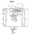
- the spindle head 4 rotatably supports a spindle 12.
- the spindle 12 has a gear 13 which engages a gear 14 fixed to a shaft 16.
- a gear 15 fixed to the shaft 16 engages a gear 17 fixed to an output shaft 18 of a motor 11.
- the shaft 18 revolves, the rotation force of the motor 11 is transmitted to the spindle 12 via the gears 17, 15, 14, 13.
- a tool holder 10 is detachably attached to a lower end of the spindle 12.
- a tool 19 is set in the tool holder 10.
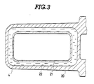
- the spindle head 4 is designed to have a double structure which includes an outer wall 20, an inner wall 21 and a circular or ring-shaped oil space formed therebetween.
- the inner wall 21 functions as a gear box 23 for the gears 13 to 17 and others.
- the inner wall 21 is formed in the shape of a rectangular parallelepiped.
- the oil space is positioned substantially over the full height of the inner wall 21 as best shown in Fig. 2.
- the side portion of the inner wall 21 is completely encircled by the oil space as shown in Fig. 3.
- the cooling oil 22 is fed from an oil tank 25 into the oil space between the outer and inner walls, by way of a line 27. Further, the cooling oil 22 is returned from the oil space to the oil tank 25 by way of a line 26.
- the cooling oil 22 is circulated so as to flow through the oil space between the outer wall 20 and the inner wall 21 of the spindle head 4 whereby the spindel head 4 can be cooled.
- the table 2 is set in a desired position.
- the column 3 moves horizontally, and the spindle head 4 moves down so that the work W on the table 2 can be machined while the spindle 12 rovolves at a high speed.
- a lot of heat is produced at the engaging portions of the gears 13 to 17, bearings 30 and others.
- the temperature of the gear box 23 increases.
- the spindle head 4 might be apt to be deformed due to the heat.
- the cooling oil 22 flows through the spindle head 4 and particularly the oil space therein, the heat is effectively transferred to the cooling oil 22 so that the temperature of the gear box 23 does not increase too much. Therefore, deformation of the spindle head or gear box can be avoided.
- the works can be precisely machined by the tool 19.
- This invention is not limited to the disclosed embodiment only.
- this invention can be applied to any type machine including a wood machine.
Landscapes
- Engineering & Computer Science (AREA)
- Mechanical Engineering (AREA)
- Auxiliary Devices For Machine Tools (AREA)
- Machine Tool Units (AREA)
Priority Applications (2)
| Application Number | Priority Date | Filing Date | Title |
|---|---|---|---|
| US07/384,810 US4952105A (en) | 1989-07-26 | 1989-07-25 | Machine tool |
| EP89113754A EP0410031A1 (fr) | 1989-07-26 | 1989-07-26 | Machine-outil |
Applications Claiming Priority (1)
| Application Number | Priority Date | Filing Date | Title |
|---|---|---|---|
| EP89113754A EP0410031A1 (fr) | 1989-07-26 | 1989-07-26 | Machine-outil |
Publications (1)
| Publication Number | Publication Date |
|---|---|
| EP0410031A1 true EP0410031A1 (fr) | 1991-01-30 |
Family
ID=8201683
Family Applications (1)
| Application Number | Title | Priority Date | Filing Date |
|---|---|---|---|
| EP89113754A Withdrawn EP0410031A1 (fr) | 1989-07-26 | 1989-07-26 | Machine-outil |
Country Status (2)
| Country | Link |
|---|---|
| US (1) | US4952105A (fr) |
| EP (1) | EP0410031A1 (fr) |
Cited By (1)
| Publication number | Priority date | Publication date | Assignee | Title |
|---|---|---|---|---|
| EP2116327A1 (fr) * | 2008-05-08 | 2009-11-11 | Siemens Aktiengesellschaft | Machine-outil dotée d'un tuyau de chauffage |
Families Citing this family (9)
| Publication number | Priority date | Publication date | Assignee | Title |
|---|---|---|---|---|
| US5442953A (en) * | 1993-10-21 | 1995-08-22 | General Electric Company | Dynamic commutator profile system |
| EP0694363B1 (fr) * | 1994-02-15 | 1999-07-07 | Seiko Seiki Kabushiki Kaisha | Machine-outil a deux broches reversibles |
| FR2723017B1 (fr) * | 1994-07-26 | 1996-10-25 | Henri Line Sa | Tete de machine-outils, dont l'enceinte porte-outils est refroidie |
| KR0156837B1 (ko) * | 1996-06-14 | 1998-11-16 | 박병재 | 크랭크 샤프트의 오일 홀의 챔퍼 가공장치 |
| US6089797A (en) * | 1998-11-30 | 2000-07-18 | Excellon Automation, Co. | Thermal equalization system |
| JP2002239857A (ja) * | 2001-02-13 | 2002-08-28 | Makino Milling Mach Co Ltd | 熱変形抑制機能を備えた工作機械 |
| JP5964159B2 (ja) * | 2012-07-05 | 2016-08-03 | 東芝機械株式会社 | 精密工作機械 |
| DE102014202878A1 (de) * | 2014-02-17 | 2015-08-20 | Deckel Maho Seebach Gmbh | Werkzeugmaschine mit im Arbeitsbetrieb wärmeerzeugenden Funktionskomponenten |
| CN108274300A (zh) * | 2018-03-20 | 2018-07-13 | 东莞市台克机械有限公司 | 一种加工中心的冷油箱 |
Citations (7)
| Publication number | Priority date | Publication date | Assignee | Title |
|---|---|---|---|---|
| US2358088A (en) * | 1942-08-25 | 1944-09-12 | Warner Swasey Co | Machine tool |
| FR1223607A (fr) * | 1959-01-31 | 1960-06-17 | Dispositif destiné à empêcher des dilatations locales dans des organes de machines dans lesquels tournent des broches porte-outils de grande capacité | |
| GB883684A (en) * | 1958-08-29 | 1961-12-06 | Siemens Schuckert Great Britia | Improvements in or relating to portable electric tools |
| CH360262A (de) * | 1958-08-20 | 1962-02-15 | Menziken Ag Maschf | Universaldrehbank |
| DE1477200A1 (de) * | 1963-04-19 | 1969-03-20 | Collet & Engelhard Maschinenfa | Einrichtung zur thermischen Stabilisierung der Arbeitsspindellage bei Waagerecht-Bohr-Fraesmaschinen |
| FR2518002A1 (fr) * | 1981-12-12 | 1983-06-17 | Honda Motor Co Ltd | Tete multiple pour machine-outil a tetes multiples interchangeables |
| EP0083943A1 (fr) * | 1982-01-11 | 1983-07-20 | Nakamuratome Seimitsu Kogyo Kabushiki Kaisha | Refroidisseur pour un bâti |
Family Cites Families (3)
| Publication number | Priority date | Publication date | Assignee | Title |
|---|---|---|---|---|
| GB773449A (en) * | 1954-09-14 | 1957-04-24 | Innocenti Soc Generale | Improvements in milling and other machines for removing the skin from hot ingots |
| US3066578A (en) * | 1958-12-17 | 1962-12-04 | Cincinnati Milling Machine Co | Temperature control of machine tool |
| US3692418A (en) * | 1970-08-28 | 1972-09-19 | Fridrikh Lvovich Kopelev | Precision boring machine |
-
1989
- 1989-07-25 US US07/384,810 patent/US4952105A/en not_active Expired - Lifetime
- 1989-07-26 EP EP89113754A patent/EP0410031A1/fr not_active Withdrawn
Patent Citations (7)
| Publication number | Priority date | Publication date | Assignee | Title |
|---|---|---|---|---|
| US2358088A (en) * | 1942-08-25 | 1944-09-12 | Warner Swasey Co | Machine tool |
| CH360262A (de) * | 1958-08-20 | 1962-02-15 | Menziken Ag Maschf | Universaldrehbank |
| GB883684A (en) * | 1958-08-29 | 1961-12-06 | Siemens Schuckert Great Britia | Improvements in or relating to portable electric tools |
| FR1223607A (fr) * | 1959-01-31 | 1960-06-17 | Dispositif destiné à empêcher des dilatations locales dans des organes de machines dans lesquels tournent des broches porte-outils de grande capacité | |
| DE1477200A1 (de) * | 1963-04-19 | 1969-03-20 | Collet & Engelhard Maschinenfa | Einrichtung zur thermischen Stabilisierung der Arbeitsspindellage bei Waagerecht-Bohr-Fraesmaschinen |
| FR2518002A1 (fr) * | 1981-12-12 | 1983-06-17 | Honda Motor Co Ltd | Tete multiple pour machine-outil a tetes multiples interchangeables |
| EP0083943A1 (fr) * | 1982-01-11 | 1983-07-20 | Nakamuratome Seimitsu Kogyo Kabushiki Kaisha | Refroidisseur pour un bâti |
Cited By (1)
| Publication number | Priority date | Publication date | Assignee | Title |
|---|---|---|---|---|
| EP2116327A1 (fr) * | 2008-05-08 | 2009-11-11 | Siemens Aktiengesellschaft | Machine-outil dotée d'un tuyau de chauffage |
Also Published As
| Publication number | Publication date |
|---|---|
| US4952105A (en) | 1990-08-28 |
Similar Documents
| Publication | Publication Date | Title |
|---|---|---|
| US7645103B2 (en) | Workpiece table arrangement | |
| US4952105A (en) | Machine tool | |
| JPS6111738B2 (fr) | ||
| CN116175209A (zh) | 一种用于五轴加工中心的摇篮转台 | |
| US3062104A (en) | Cooling system for rotatable machine components, especially in machine tools | |
| US20050271488A1 (en) | Machine tool for working ring-shaped workpieces | |
| CN110976925A (zh) | 一种双立墙式全气体静压立式车床 | |
| JP2007508953A (ja) | 多機能部品保持ユニット装置 | |
| US4842457A (en) | Machine tool with improved spindlehead mounting and traversing means | |
| US4909293A (en) | Tool assembly for woodworking machines | |
| EP4316703A1 (fr) | Machine-outil | |
| US6056487A (en) | Compact, high through-put gear machine | |
| KR102625091B1 (ko) | 선반 공구장치 | |
| KR100477152B1 (ko) | 단일 프레임 구조를 갖는 수직형 밀링 머신의 헤드 장치 | |
| KR950003042B1 (ko) | 공작기계의 냉각장치 | |
| KR20170018575A (ko) | 공작기계용 자동공구교환장치 | |
| JPH058147A (ja) | 工作機械 | |
| EP0060453A2 (fr) | Unité de surfaçage à commande numérique pour machines-outils à tête comprenant de multiples broches | |
| JPH01193142A (ja) | 工作機械 | |
| US4385855A (en) | Hobbing machine | |
| CN218556249U (zh) | 三轴传动装置置于箱顶式的加工中心机床 | |
| KR100192558B1 (ko) | 수직선반용 턴밀 터릿 | |
| CN111300082B (zh) | 一种铣床主轴 | |
| JP7678010B6 (ja) | 揺動器の回転制御装置、及び、それを用いた工作機械 | |
| KR200237552Y1 (ko) | 머시닝 센터용 자동공구교환기의 아암장치 |
Legal Events
| Date | Code | Title | Description |
|---|---|---|---|
| PUAI | Public reference made under article 153(3) epc to a published international application that has entered the european phase |
Free format text: ORIGINAL CODE: 0009012 |
|
| AK | Designated contracting states |
Kind code of ref document: A1 Designated state(s): DE FR GB IT |
|
| 17P | Request for examination filed |
Effective date: 19901220 |
|
| 17Q | First examination report despatched |
Effective date: 19910814 |
|
| STAA | Information on the status of an ep patent application or granted ep patent |
Free format text: STATUS: THE APPLICATION IS DEEMED TO BE WITHDRAWN |
|
| 18D | Application deemed to be withdrawn |
Effective date: 19930706 |