EP0410150A2 - Pompe à engrenages - Google Patents
Pompe à engrenages Download PDFInfo
- Publication number
- EP0410150A2 EP0410150A2 EP19900112100 EP90112100A EP0410150A2 EP 0410150 A2 EP0410150 A2 EP 0410150A2 EP 19900112100 EP19900112100 EP 19900112100 EP 90112100 A EP90112100 A EP 90112100A EP 0410150 A2 EP0410150 A2 EP 0410150A2
- Authority
- EP
- European Patent Office
- Prior art keywords
- pressure
- sealing plate
- gear
- pump
- high pressure
- Prior art date
- Legal status (The legal status is an assumption and is not a legal conclusion. Google has not performed a legal analysis and makes no representation as to the accuracy of the status listed.)
- Withdrawn
Links
Images


Classifications
-
- F—MECHANICAL ENGINEERING; LIGHTING; HEATING; WEAPONS; BLASTING
- F04—POSITIVE - DISPLACEMENT MACHINES FOR LIQUIDS; PUMPS FOR LIQUIDS OR ELASTIC FLUIDS
- F04C—ROTARY-PISTON, OR OSCILLATING-PISTON, POSITIVE-DISPLACEMENT MACHINES FOR LIQUIDS; ROTARY-PISTON, OR OSCILLATING-PISTON, POSITIVE-DISPLACEMENT PUMPS
- F04C14/00—Control of, monitoring of, or safety arrangements for, machines, pumps or pumping installations
- F04C14/24—Control of, monitoring of, or safety arrangements for, machines, pumps or pumping installations characterised by using valves controlling pressure or flow rate, e.g. discharge valves or unloading valves
- F04C14/26—Control of, monitoring of, or safety arrangements for, machines, pumps or pumping installations characterised by using valves controlling pressure or flow rate, e.g. discharge valves or unloading valves using bypass channels
- F04C14/265—Control of, monitoring of, or safety arrangements for, machines, pumps or pumping installations characterised by using valves controlling pressure or flow rate, e.g. discharge valves or unloading valves using bypass channels being obtained by displacing a lateral sealing face
-
- F—MECHANICAL ENGINEERING; LIGHTING; HEATING; WEAPONS; BLASTING
- F04—POSITIVE - DISPLACEMENT MACHINES FOR LIQUIDS; PUMPS FOR LIQUIDS OR ELASTIC FLUIDS
- F04C—ROTARY-PISTON, OR OSCILLATING-PISTON, POSITIVE-DISPLACEMENT MACHINES FOR LIQUIDS; ROTARY-PISTON, OR OSCILLATING-PISTON, POSITIVE-DISPLACEMENT PUMPS
- F04C15/00—Component parts, details or accessories of machines, pumps or pumping installations, not provided for in groups F04C2/00 - F04C14/00
- F04C15/0003—Sealing arrangements in rotary-piston machines or pumps
- F04C15/0023—Axial sealings for working fluid
- F04C15/0026—Elements specially adapted for sealing of the lateral faces of intermeshing-engagement type machines or pumps, e.g. gear machines or pumps
Definitions
- the invention relates to a gear pump according to the preamble of the main claim.
- the sealing plate functions to a certain extent as a current regulator since, when the pressure fields are acted upon accordingly, part of the pressure medium conveyed by the pump can flow directly from the high pressure to the low pressure side along the gear side surfaces. Under certain circumstances, the regulated pressure medium heats up very strongly; it is immediately returned to the suction side of the pump, which can lead to overheating of the pump.
- the gear pump according to the invention with the characterizing features of the main claim has the advantage that the regulated pressure medium is not led to the suction side of the pump, but in the reservoir, where it mixes with the pressure medium there and is cooled accordingly.
- the pump therefore does not draw in pressure medium that has been heated up as intensely as was previously the case.
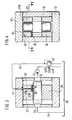
- FIG. 1 shows a longitudinal section through a gear pump, in FIG. 2 a section along II-II according to FIG. 1, in FIG. 3 a section along III-III according to FIG. 2, in FIG. 4 a section along IV-IV according to FIG. 2, in Figures 5 to 8 individual parts in longitudinal section and in plan view, in Figure 9 is a schematic diagram.
- 10 denotes the housing of a gear pump, which has an interior 11 with the cross-sectional shape of an eight and which is closed on both sides by covers 12, 13.
- two gears 14, 15 mesh with one another in external engagement.
- Their shaft journals 16, 17 are mounted in bushings 18 to 21, which are arranged in bores 22 to 25 of glasses-shaped bearing bodies 26, 27, which rest against the covers 12, 13 with little axial play.
- the shaft journal 17 has an extension 17A which penetrates through a bore 13A in the cover 13 and serves to drive the gear pump.
- the sealing plate 30 is arranged in a suitable recess 27A of the glasses 27, has approximately the shape of a three and is located on the high-pressure side HD of the pump.
- the inlet bore 33 is formed in the housing 10, which is connected to the container 35 via a suction line 34.
- the sealing plate 30 only partially covers the gear side surfaces, that is, not even half of them. As already explained above, it is located on the high pressure side and has the shape of a three. Its straight boundary line 30A has a small distance a from an imaginary straight line connecting the shaft centers. Above the sealing plate 30, two of the pressure fields A and B are formed, which are delimited by seals 36, 37. The seal 37 extends around the shaft bores and ends at the boundary line 30A. The seal 36 extends concentrically radially outside and has a certain distance from the inner wall of the housing. The pressure field A is between the seal 36 and the housing inner wall, while the pressure field B is between the two seals.
- the pressure field A is always acted on from the high pressure side - that is, the pump delivery pressure - via a recess 38 which extends along the interior of the housing.
- the pressure field B is acted upon by a small bore 39 which penetrates through the sealing plate 30 - see in particular FIG. 3 in this regard - and ends at the tooth chambers. From this it can be seen that the pressure in the tooth chambers - it is also the delivery pressure of the pump - also prevails in the pressure field B.
- a bore 40 adjoins the bore 39 in the bearing body 27, which bore has a connection to a bore 41 penetrating the cover.
- a line 42 is connected to this bore, in which there is an electromagnetically actuated control valve 43 and which leads to the container 35.
- longitudinal grooves 45, 46 are formed on the two sleeves 18, 19 on their inner sides facing the sealing plate, which extend over the entire length of the sleeves.
- the longitudinal groove is designated 46. In the sectional view of Figure 2, these longitudinal grooves are shown as broad lines (numbers 45, 46).
- a flat recess 27B is formed on the side of the bearing body 27 facing the cover 12.
- FIG. 8 shows a view of this end face of the bearing body 27. From this it can be seen that the recess 27B is relatively narrow, so that on the end face of the bearing body 27 there is still space for a pressure field 27E which acts on the high pressure side and so on is dimensioned that it presses the bearing body slightly against the gear side surfaces.
- the pressure in the pressure field B can be varied continuously by appropriate switching of the solenoid valve 43.
- the valve 43 When the valve 43 is closed, the pump delivery pressure practically prevails in the pressure field B, which - as described above - reaches the pressure field via the bore 39.
- the delivery pressure of the pump always prevails in pressure field A.
- valve 43 If the valve 43 is opened by appropriate actuation of its electromagnet 43A, pressure medium can flow out of the pressure field B via the bores 40, 41 as well as the line 42 and the valve 43 to the container.
- the sealing plate 30 is now more or less lifted off the gear side surfaces by the pressure prevailing below it in the tooth chambers. This allows pressure medium to flow from the high pressure side below the plate. Due to the shape of the pressure plate, this outflowing pressure medium reaches the longitudinal grooves 45, 46 of the bushings 18, 19 and to the recess 27A on the bearing body 27. From there it flows through the bore 48 and through the interior of the gear pump into the container 35.
- the sealing plate 30 can be lifted more or less strongly from the gear side surfaces, as a result of which a more or less large amount of pressure medium can flow from the high pressure side to the longitudinal grooves 45, 46. It can get very hot, but is cooled again by the fact that it flows into the pressure vessel. Thus, no pressure medium heated on the sealing plate by frictional force flows directly to the suction side. If the valve 43 is completely closed, the sealing plate lies fully against the gear side surfaces so that no pressure medium can flow away from the high to the low pressure side. The delivery rate is now maximum.
- the sealing plate has the function of a flow control valve by correspondingly controlling the pressure in the pressure field B, as a result of which the delivery rate of the pump can be regulated in the simplest way. Overheating of the gear pump is reliably avoided in that the pressure medium which is deactivated in the bypass flows to the container and is cooled there.
- the pressure control is shown schematically in FIG.
- the sealing plate 30 is shown here as a bypass valve, which function it also has.
- the current flowing through the sealing plate is designated Q V
- the low pressure medium flow flowing out of the pressure field B is designated Q S. It can be clearly seen here that the pressure medium flowing out via the sealing plate 30 reaches the container 35 directly.
- the pressure in the pressure field B can also be controlled in another way than by means of the control valve 43, for. B. by an external pressure control device (auxiliary pump, hydraulic system, pressure accumulator, etc.).
- a sealing plate 30 can also be arranged on both gear side surfaces, if this is necessary.
Landscapes
- Engineering & Computer Science (AREA)
- Mechanical Engineering (AREA)
- General Engineering & Computer Science (AREA)
- Physics & Mathematics (AREA)
- Fluid Mechanics (AREA)
- Rotary Pumps (AREA)
- Details And Applications Of Rotary Liquid Pumps (AREA)
Applications Claiming Priority (2)
| Application Number | Priority Date | Filing Date | Title |
|---|---|---|---|
| DE19893924482 DE3924482A1 (de) | 1989-07-25 | 1989-07-25 | Zahnradpumpe |
| DE3924482 | 1989-07-25 |
Publications (2)
| Publication Number | Publication Date |
|---|---|
| EP0410150A2 true EP0410150A2 (fr) | 1991-01-30 |
| EP0410150A3 EP0410150A3 (en) | 1991-11-27 |
Family
ID=6385721
Family Applications (1)
| Application Number | Title | Priority Date | Filing Date |
|---|---|---|---|
| EP19900112100 Withdrawn EP0410150A3 (en) | 1989-07-25 | 1990-06-26 | Gear pump |
Country Status (2)
| Country | Link |
|---|---|
| EP (1) | EP0410150A3 (fr) |
| DE (1) | DE3924482A1 (fr) |
Cited By (3)
| Publication number | Priority date | Publication date | Assignee | Title |
|---|---|---|---|---|
| WO2012048940A2 (fr) | 2010-10-14 | 2012-04-19 | Robert Bosch Gmbh | Pompe à engrenages pour déplacer un liquide |
| CN108612651A (zh) * | 2018-07-13 | 2018-10-02 | 杜马司科学仪器(江苏)有限公司 | 一种真空液体出料泵及减压蒸馏装置 |
| CN108678948A (zh) * | 2018-04-28 | 2018-10-19 | 河南航天液压气动技术有限公司 | 一种液压系统及其齿轮泵 |
Families Citing this family (2)
| Publication number | Priority date | Publication date | Assignee | Title |
|---|---|---|---|---|
| DE4423096A1 (de) * | 1994-07-01 | 1996-01-04 | Alois Boerger | Rotorpumpe |
| DE102010050163A1 (de) | 2010-10-30 | 2012-05-03 | Iav Gmbh Ingenieurgesellschaft Auto Und Verkehr | Verdrängermaschine mit reduziertem Betriebsgeräusch |
Family Cites Families (6)
| Publication number | Priority date | Publication date | Assignee | Title |
|---|---|---|---|---|
| DE944595C (de) * | 1950-06-16 | 1956-06-21 | Borg Warner | Hochdruckfluessigkeitszahnradpumpe |
| DE1528954A1 (de) * | 1964-08-08 | 1970-07-02 | Bosch Gmbh Robert | Verdraengermaschine |
| GB1526080A (en) * | 1974-12-12 | 1978-09-27 | Jacquard Syst | Embossing machine |
| NL169509C (nl) * | 1978-02-07 | 1982-07-16 | Fuelmaster Prod Nv | Roterende pomp. |
| DE2853833A1 (de) * | 1978-12-13 | 1980-07-03 | Rickmeier Pumpen | Zahnradpumpe fuer wasser o.dgl. |
| DE8806388U1 (de) * | 1987-09-10 | 1989-01-12 | Robert Bosch Gmbh, 7000 Stuttgart | Zahnradmotor |
-
1989
- 1989-07-25 DE DE19893924482 patent/DE3924482A1/de active Granted
-
1990
- 1990-06-26 EP EP19900112100 patent/EP0410150A3/de not_active Withdrawn
Cited By (4)
| Publication number | Priority date | Publication date | Assignee | Title |
|---|---|---|---|---|
| WO2012048940A2 (fr) | 2010-10-14 | 2012-04-19 | Robert Bosch Gmbh | Pompe à engrenages pour déplacer un liquide |
| DE102010042455A1 (de) | 2010-10-14 | 2012-04-19 | Robert Bosch Gmbh | Zahnradpumpe zur Förderung einer Flüssigkeit |
| CN108678948A (zh) * | 2018-04-28 | 2018-10-19 | 河南航天液压气动技术有限公司 | 一种液压系统及其齿轮泵 |
| CN108612651A (zh) * | 2018-07-13 | 2018-10-02 | 杜马司科学仪器(江苏)有限公司 | 一种真空液体出料泵及减压蒸馏装置 |
Also Published As
| Publication number | Publication date |
|---|---|
| DE3924482A1 (de) | 1991-02-07 |
| DE3924482C2 (fr) | 1991-05-16 |
| EP0410150A3 (en) | 1991-11-27 |
Similar Documents
| Publication | Publication Date | Title |
|---|---|---|
| DE19846815B4 (de) | Ventilanordnung und Pumpe für ein Getriebe | |
| DE19500749C2 (de) | Drei- oder Mehr-Wege-Ventil | |
| DE10258517B3 (de) | Hydraulische Ventilanordnung | |
| EP0103250B1 (fr) | Soupape de contrôle pour contrôle hydraulique | |
| EP0650558B1 (fr) | Dispositif de commande pour au moins un consommateur hydraulique | |
| EP0377617B1 (fr) | Moteur turbinaire a engrenages | |
| DE19717807B4 (de) | Von mindestens einem Elektromagneten betätigbares Wegeventil | |
| DE2523894C3 (de) | Hydraulische Servomotorenanlage | |
| EP1984629B1 (fr) | Systeme de commande hydraulique a regeneration et soupape de frein d'abaissement | |
| EP0410150A2 (fr) | Pompe à engrenages | |
| WO1995033136A1 (fr) | Systeme de regulation d'un dispositif de levage avec soupape de regulation | |
| DE3519148C2 (fr) | ||
| EP0743460A1 (fr) | Module de levage électrohydraulique | |
| DE19705827A1 (de) | Hydrauliksysteme | |
| DE19500748C2 (de) | Drei- oder Mehr-Wege-Ventil | |
| WO2008031390A1 (fr) | système hydraulique d'amenée d'un fluide hydraulique à un consommateur | |
| DE19522744B4 (de) | Elektrohydraulische Steuervorrichtung | |
| DE4036696C2 (de) | Membranpumpe | |
| DE10023583A1 (de) | Elektrohydraulischer Senken-Modul | |
| DE3919939C2 (de) | Hydrostatischer Antrieb | |
| EP0379697B1 (fr) | Entraînement hydrostatique | |
| EP0342346A2 (fr) | Pompe à engrenages | |
| DE19948390B4 (de) | Ventilanordnung | |
| DE10224827A1 (de) | Hydraulische Ventilanordnung | |
| DE1403320C (de) | Hydraulisch wirkender Pumpenschutzschalter |
Legal Events
| Date | Code | Title | Description |
|---|---|---|---|
| PUAI | Public reference made under article 153(3) epc to a published international application that has entered the european phase |
Free format text: ORIGINAL CODE: 0009012 |
|
| AK | Designated contracting states |
Kind code of ref document: A2 Designated state(s): DE FR GB IT |
|
| PUAL | Search report despatched |
Free format text: ORIGINAL CODE: 0009013 |
|
| AK | Designated contracting states |
Kind code of ref document: A3 Designated state(s): DE FR GB IT |
|
| RHK1 | Main classification (correction) |
Ipc: F04C 2/14 |
|
| RAP3 | Party data changed (applicant data changed or rights of an application transferred) |
Owner name: ROBERT BOSCH GMBH |
|
| 17P | Request for examination filed |
Effective date: 19920502 |
|
| 17Q | First examination report despatched |
Effective date: 19930125 |
|
| STAA | Information on the status of an ep patent application or granted ep patent |
Free format text: STATUS: THE APPLICATION IS DEEMED TO BE WITHDRAWN |
|
| 18D | Application deemed to be withdrawn |
Effective date: 19940213 |