EP0410181A2 - Lösbare Verbindung für faseroptische Flachbandkabel und Methode ihrer Herstellung - Google Patents
Lösbare Verbindung für faseroptische Flachbandkabel und Methode ihrer Herstellung Download PDFInfo
- Publication number
- EP0410181A2 EP0410181A2 EP90112926A EP90112926A EP0410181A2 EP 0410181 A2 EP0410181 A2 EP 0410181A2 EP 90112926 A EP90112926 A EP 90112926A EP 90112926 A EP90112926 A EP 90112926A EP 0410181 A2 EP0410181 A2 EP 0410181A2
- Authority
- EP
- European Patent Office
- Prior art keywords
- optical fibers
- plate
- grooves
- plates
- ribbon
- Prior art date
- Legal status (The legal status is an assumption and is not a legal conclusion. Google has not performed a legal analysis and makes no representation as to the accuracy of the status listed.)
- Ceased
Links
Images


Classifications
-
- G—PHYSICS
- G02—OPTICS
- G02B—OPTICAL ELEMENTS, SYSTEMS OR APPARATUS
- G02B6/00—Light guides; Structural details of arrangements comprising light guides and other optical elements, e.g. couplings
- G02B6/24—Coupling light guides
- G02B6/36—Mechanical coupling means
- G02B6/38—Mechanical coupling means having fibre to fibre mating means
- G02B6/3807—Dismountable connectors, i.e. comprising plugs
- G02B6/381—Dismountable connectors, i.e. comprising plugs of the ferrule type, e.g. fibre ends embedded in ferrules, connecting a pair of fibres
- G02B6/3826—Dismountable connectors, i.e. comprising plugs of the ferrule type, e.g. fibre ends embedded in ferrules, connecting a pair of fibres characterised by form or shape
- G02B6/383—Hermaphroditic connectors, i.e. two identical plugs mating with one another, each plug having both male and female diametrically opposed engaging parts
-
- G—PHYSICS
- G02—OPTICS
- G02B—OPTICAL ELEMENTS, SYSTEMS OR APPARATUS
- G02B6/00—Light guides; Structural details of arrangements comprising light guides and other optical elements, e.g. couplings
- G02B6/24—Coupling light guides
- G02B6/36—Mechanical coupling means
- G02B6/38—Mechanical coupling means having fibre to fibre mating means
- G02B6/3801—Permanent connections, i.e. wherein fibres are kept aligned by mechanical means
- G02B6/3803—Adjustment or alignment devices for alignment prior to splicing
-
- G—PHYSICS
- G02—OPTICS
- G02B—OPTICAL ELEMENTS, SYSTEMS OR APPARATUS
- G02B6/00—Light guides; Structural details of arrangements comprising light guides and other optical elements, e.g. couplings
- G02B6/24—Coupling light guides
- G02B6/36—Mechanical coupling means
- G02B6/38—Mechanical coupling means having fibre to fibre mating means
- G02B6/3807—Dismountable connectors, i.e. comprising plugs
- G02B6/3833—Details of mounting fibres in ferrules; Assembly methods; Manufacture
- G02B6/3834—Means for centering or aligning the light guide within the ferrule
- G02B6/3838—Means for centering or aligning the light guide within the ferrule using grooves for light guides
- G02B6/3839—Means for centering or aligning the light guide within the ferrule using grooves for light guides for a plurality of light guides
-
- G—PHYSICS
- G02—OPTICS
- G02B—OPTICAL ELEMENTS, SYSTEMS OR APPARATUS
- G02B6/00—Light guides; Structural details of arrangements comprising light guides and other optical elements, e.g. couplings
- G02B6/24—Coupling light guides
- G02B6/36—Mechanical coupling means
- G02B6/38—Mechanical coupling means having fibre to fibre mating means
- G02B6/3807—Dismountable connectors, i.e. comprising plugs
- G02B6/3873—Connectors using guide surfaces for aligning ferrule ends, e.g. tubes, sleeves, V-grooves, rods, pins, balls
- G02B6/3885—Multicore or multichannel optical connectors, i.e. one single ferrule containing more than one fibre, e.g. ribbon type
-
- G—PHYSICS
- G02—OPTICS
- G02B—OPTICAL ELEMENTS, SYSTEMS OR APPARATUS
- G02B6/00—Light guides; Structural details of arrangements comprising light guides and other optical elements, e.g. couplings
- G02B6/24—Coupling light guides
- G02B6/36—Mechanical coupling means
- G02B6/3628—Mechanical coupling means for mounting fibres to supporting carriers
- G02B6/3648—Supporting carriers of a microbench type, i.e. with micromachined additional mechanical structures
- G02B6/3652—Supporting carriers of a microbench type, i.e. with micromachined additional mechanical structures the additional structures being prepositioning mounting areas, allowing only movement in one dimension, e.g. grooves, trenches or vias in the microbench surface, i.e. self aligning supporting carriers
-
- G—PHYSICS
- G02—OPTICS
- G02B—OPTICAL ELEMENTS, SYSTEMS OR APPARATUS
- G02B6/00—Light guides; Structural details of arrangements comprising light guides and other optical elements, e.g. couplings
- G02B6/24—Coupling light guides
- G02B6/36—Mechanical coupling means
- G02B6/38—Mechanical coupling means having fibre to fibre mating means
- G02B6/3807—Dismountable connectors, i.e. comprising plugs
- G02B6/3833—Details of mounting fibres in ferrules; Assembly methods; Manufacture
- G02B6/3855—Details of mounting fibres in ferrules; Assembly methods; Manufacture characterised by the method of anchoring or fixing the fibre within the ferrule
- G02B6/3861—Adhesive bonding
Definitions
- the present invention relates to a connecting unit for ribbon-joined optical fibers and to a method of making the same.
- the end of the ribbon itself is conveniently fitted into a rigid body, referred to as connector, which keeps the fibers in a geometrically definite position; two connectors forming a pair are therefore disposed and held in a confronting relationship and so aligned that the respective fibers can take the correct position for forming the optical connection.
- optical fibers are housed inside the grooves of a plate made of a crystalline material which are obtained during several steps by localized etching, at positions defined by protection templates.
- optical connectors with coupling plugs comprising a base plate provided with grooves to receive the optical fibers and guide plugs to which a flat plate of smaller sizes is fastened; the plates define holes between each other and into said holes the guide plugs and fibers are subsequently introduced.
- the base plate has an uncovered portion the grooves of which represent a guide for the introduction of the fibers.
- These connectors are made of a hard and brittle material, such as crystalline silicon or ceramics and the grooves are formed by removal of material by means of very precise grinding machines adapted to ensure the requested tolerance values, necessary for the optical coupling of the fibers.
- the present invention aims at solving the technical problem involving the accomplishment of connecting elements capable of ensuring a very precise optical alignment in connections, while avoiding the alignment faults due both to the working tolerances and to the presence of clearances between the fibers and the respective guide housings, by adopting a process entailing relatively low costs, and at the same time ensuring the interchangeability between the connectors of each series and where the connectors can offer a faultless mounting whether it is carried out at the factory or on the stocks.
- each connector consists of a pair of coupled plates rigidly fastened to each other and clamping two or more optical fibers belonging to a ribbon made of parallel optical fibers as well as an alignment plug means, at least one plate in each connector comprising an element made of a plastically deformable metallic material provided with housing grooves for the optical fibers of the ribbon from which the common coating has been removed and for the alignment plug means, which grooves have been formed therein by cold plastic deformation using the same punch for all the plates being part of an interchangeable series, the alignment plugs and the fibers of the fiber ribbon being accommodated within the respective grooves
- At least a plate for each connector has a pair of alignment grooves of substantially triangular section on one surface thereof, which grooves are adapted to partially accommodate respective alignment plugs. Located between these alignment grooves are two or more grooves of substantially triangular section adapted to partially receive corresponding optical fibers of a fiber ribbon from which the common coating has been removed (bare optical fibers), the grooves being formed by cold plastic deformation.
- Each plate at one end thereof has a slot adapted to accommodate a length of coated optical fiber ribbon contiguous to the bare fiber length located in the grooves.
- the slot in each plate provided with grooves is made at a definite position with respect to the longitudinal orientation of the plate at the moment of forming the grooves.
- the slots in the plates are alternatively formed at either end of the plates, depending upon the longitudinal orientation of the plate when the grooves are being formed, an identification means for recognizing this orientation being present on the plates at the forming.
- the identification means for recognizing the orientation of the plates at the forming consists of marks associated with the plate and independent of the respective grooves, said marks comprising side notches, colourings, side asymmetries and the like; said means may also be embodied by differently sized grooves designed to house the alignment plugs in each plate.
- the positions of the slots relative to the orientation of the plates define two groups of plates, designated as right and left plates respectively, two connectors being coupled to each other with at least a respective right plate in alignment with a left plate.
- each connector is formed with two plates each having a surface provided with grooves adapted to accommodate alignment plugs and optical fibers, the plates being coupled to each other so that the respective grooved surfaces are faced and the grooves are in register, the grooves which in each plate are designed to accommodate the plugs and the optical fibers being dimensioned so as to receive said plugs and fibers with the respective axes in coplanar relation, overlying the surface of the plate itself in which the grooves are formed.
- each connector is formed with two plates, left and right respectively.
- At least the plate grooves adapted to accommodate the optical fibers have sides with flat portions, at least at the area in contact with the fibers, forming a dihedral the apex angle of which ranges between 80° and 100°.
- At least a plate for each connector has a hole in the middle for inserting metered adhesive material susceptible of hardening between the plates of the connector itself.
- a connector is formed with a plate having one surface provided with grooves adapted to receive alignment plugs and optical fibers coupled and fastened to a plate of identical width having a flat surface in the area overlying the fibers, the optical fibers being clamped between the groove sides and said flat surface.
- the grooves designed to receive the plugs and the optical fibers in each grooved plate can be dimensioned so as to receive the plugs and fibers with a common tangent plane, in each connector the grooved plate being coupled to a plate having one flat surface in contact with the fibers and the alignment plugs.
- the two coupled connectors have a plate provided with right grooves and a plate provided with left grooves respectively.
- the grooves adapted to receive the plugs and the optical fibers in each grooved plate are dimensioned so as to accommodate the plugs and optical fibers with the respective axes in coplanar relationship, the grooved plates being each coupled to a plate having recessed surfaces at the respective contact areas with the alignment plugs.
- the slots in the grooved plates can be alternatively formed at either end of the plates depending upon the longitudinal orientation of the plate when the grooves are formed and two connectors having a right grooved plate and a left grooved plate respectively are coupled to each other as in the preceding case, or said slots can be formed on the same side relative to the orientation of the plates when the grooves are formed.
- At least the grooves in the plates adapted to receive the optical fibers have sides with flat portions, at least at the area in contact with the fibers, forming a dihedral the apex angle of which ranges between 50° and 90°.
- the plate having a substantially flat surface in the area overlying the fibers, at its portions designed to overlie the alignment plugs is provided with respective areas having a reduced thickness so as to allow the elastic flexional deformability of said portions.
- the method of accomplishing connectors for detachable connecting groups to be used wit ribbon-joined optical fibers is characterized in that it comprises the following steps: making a punch having a predetermined profile comprising several parallel or substantially parallel ridges; forming a plurality of plates made of metallic material with said punch by cold plastic deformation, said plates on one face having an impression corresponding to the punch and provided with several parallel or substantially parallel grooves; accommodating the optical fibers belonging to an optical fiber ribbon, on a length of which the common coating has been removed, into some of the grooves of one plate inside which they are partially contained; associating a grooved plate with a second plate, clamping the fibers between the associated plates; applying a metered amount of adhesive susceptible of hardening between the two plates and keeping the plates clamped against the optical fibers until the adhesive has hardened; grinding the surface of the assembly where the fiber ends come out; and introducing at least an alingment plug into one of said grooves clear of said optical fibers.
- the punch at least for one series of grooved plates is unique and common to all the grooved plates.
- the method provides for the grooved plates produced by the punch to be periodically controlled, the punch being replaced when the groove sizes come close to the predetermined tolerance values.
- a slot is formed by removal of material at a definite location relative to the orientation of the plate during the formation of the grooves.
- Applied to the grooved plate is an identification mark relative to the position of the slot with respect to the orientation of the plate when the grooves are formed.
- two grooved plates made with the same punch and in which the slots are located at opposite positions relative to the orientation of the plate when the grooves are formed can be associated with each other, so as to clamp the optical fibers of the optical fiber ribbon.
- a grooved plate and a plate with a flat surface in the area overlying the fibers can be associated with each other.
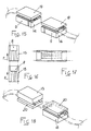
- connection between two optical fiber ribbons is made by means of a pair of connectors 1, 2 integral to the corresponding ends of optical fiber ribbons 3, 4, disposed in confronting relationship with respect to each other; the connectors are accommodated in an outer housing or at all events kept in mutual contact by an outer retaining means not shown as it is not part of the present invention.
- Each connector shown in an exploded view in the drawings, consists of a pair of plates 5 equal to each other and provided with longitudinal grooves 6 into which the optical fiber bare ends 7 (that is the lengths devoid of the protecting coating plastics material so that the outer layer or cladding of the optical fibers is exposed) of ribbons 3, 4 are placed; a slot 8 formed at the end of the plate allows the end portion of the plastics coating of greater thickness to be housed therein.
- a pair of further longitudinal grooves 9 receives the plugs 10, preferably one for each connector, designed to be introduced into the corresponding grooves of the other connector and through which the connectors themselves are coupled to each other so that an alignment condition in the connection is created.
- each plate 5 has several grooves 6 with a V-shaped sectional outline, within which the optical fibers 7 of the ribbon-joined cables 3 or 4 are received; when two plates 5 are paired the fibers 7 are held within the inclined planes of the grooves themselves, their geometrical position being defined by the conformation of the grooves.
- the depth of grooves 6 is established depending upon the outer diameter ⁇ of the fiber, so as an empty space s of predetermined value between the plates may be left; as the plates are identical with each other, the axis a of the core of each fiber is disposed in an intermediate position between the plates.
- One of the plates forming a connector or both of them are provided with a hole 11, more clearly shown in Fig. 1, through which a metered amount of adhesive hardening resin 12 is cast between the two plates 5 held tightened against the fibers 7 according to a predetermined strength.
- Said metered amount of resin fills the empty space of thickness s between the plates as well as the space between the grooves 6 clear of the fibers, rigidly clamping the two plates to each other and the fibers contained therein; the amount of adhesive is provided so that it may fill the area between the plates involving the fibers without however reaching the grooves 9 so that the introduction thereinto of the plugs 10 is not hindered.
- the front surface A of the connector thus formed designed to carry out the contact with the corresponding surface of the connector mounted to the end of the other cable is submitted to a grinding operation ensuring the perfect flatness and smoothness of the optical fibers to be connected.
- the plates 5 are made of a metallic material by cold plastic deformation, also referred to as coining.
- a punch P is manufactured as shown in Fig. 3, which is provided with projecting ridges C, C′ adapted to form the desired grooves in the plates.
- the grooved plates 5b are coined by the punch P, in which plates grooves 6 and 9 are extended over the whole length of the same.
- the grooved plates 5b are then machined, for example milled, so as to form the slots 8 therein as shown in Fig. 5 in order to create plates ready to be mounted, generally identified by reference numeral 5.
- Plates 5 can therefore be coupled to each other, as previously described, and therefore give rise to a finished connector.
- the grooved plates 5 are coined in the desired number by the punch P which is obtained by mechanical high precision working; by virtue of the above procedure, plates 5 are strictly equal to one another, at least as far as a great number of pieces produced with the same punch before its being worn are concerned, and therefore as regards the connectors formed with said plates a complete compatibility and interchangeability is ensured with a very reduced attenuation of the transmitted signal.
- the punch is of one piece construction, it can be worked in a very precise manner; on the other hand, the connectors formed by adopting the above method can ensure the coupling with the fibers in a condition of perfect alignment, as previously stated, even if the punch does not offer very high qualities as regards accuracy in size, in particular as far as the pitch between the grooves is concerned.
- the punch through a common mechanical precision working, in which the ridges adapted to give rise to the grooves 6, 9 in the plates coined by said punch are for example formed by a grinding operation on the punch itself, it is usually possible to keep a satisfactory degree of parallelism between the ridges, and therefore between the plate grooves, whereas the precision of the machine tool used can be insufficient to ensure the center-to-center constancy between the different ridges of the punch, because the required tolerance is very reduced.
- two identical plates obtained with the same punch are coupled to each other; in this way a possible lack of precision in the distance between the centers of two grooves can be ignored because the real center-to-center values are at all events kept constant in the different pieces.
- the plates after coining are given an appropriate orientation, a front part and a rear part being established for each of them, that is a surface designed to face the contiguous connector and an opposite surface designed to receive the fiber ribbon when a connector is formed with said plate; it results therefore that for a correct coupling the plates to be coupled must be selected with opposite orientations with respect to the direction according to which they have been coined.
- This "front-rear" orientation can be conveniently defined by the slot 8 which can univocally establish the surface in the plate where the fiber ribbon is to be inserted; as shown in Figs 5 and 7 a correct overlapping can be achieved with plates in which the grooves 8 are oriented in opposite ways with respect to the direction of the plates themselves at the coining, shown by arrows F.
- the identification of the plates can take place by means of marks etched on one of the sides, or different colourings, shapes or the like; for example a notch 13 always etched on the same side relative to the coining orientation of the plates identified by arrow F is shown in Fig. 7.
- the notch 13 can then be disposed to the right of a person regarding the plates in the above defined front-rear direction or to his left as shown in Fig. 7 on the upper and lower plates respectively.
- the acknowledgement and correct coupling of right and left plates can be achieved by providing asymmetrical alignement plugs, for example plugs having different diameter depending whether they are located to the right or to the left of the fibers: in this case, being the slots 8 formed as shown in Fig. 7, an incorrect mounting of the plates appears impossible or at all events can be immediately recognized as the introduction of the plugs into the respective grooves is prevented.
- asymmetrical alignement plugs for example plugs having different diameter depending whether they are located to the right or to the left of the fibers: in this case, being the slots 8 formed as shown in Fig. 7, an incorrect mounting of the plates appears impossible or at all events can be immediately recognized as the introduction of the plugs into the respective grooves is prevented.
- the plates of the two connectors to be coupled must have opposite arrangement, that is a left (S) plate must always face a right (D) plate.
- a groove section in the form of an isosceles triangle is preferred, in which the apex angle ⁇ is in the range of 80° to 100°, and preferably equal to 90°.
- bottoms of grooves 9 and 6, beyond the area in which they may interfere with plugs 10 and fibers 7 respectively, can be radiused, bevelled or relieved, depending upon the working requirements of the punch and so on; similarly the edges between the groove sides and the plate plane in areas far apart from the contact positions with the fibers or plugs, can be radiused or chamfered.
- the grooves can also have differently shaped sides, and curved, stepped or similar surfaces can be provided.
- a plate 14 or 15 by coining, provided with grooves 16 adapted to receive the fibers 7 and with grooves 17 or 18 for receiving the alignment plugs 10 respectively, and designed to form a connector when associated with a second plate of different form.
- the plate 14 is associated with a covering plate 19 of identical extension having a flat surface; the grooves are formed to such a depth and inclination of the sides that they can receive the plugs 10 while keeping the upper tangent plane thereof level with the tangent plane of the fibers 7.
- the axis of the plugs 10 is not in coplanar relation with the axis of the fibers 7, when two connectors have to be coupled the corresponding plates 14 and 19 are disposed in confronting relationship with each other according to the diagram shown in Fig. 15; the coupling of the connectors takes place with a right type plate in one case and with a left type plate in the other case, as already defined with reference to the diagram shown in Fig. 7.
- This embodiment allows the fibers and plugs to be received between three planes, so that redundant engagements are avoided and in this case it is only necessary to establish the flatness of the coupling surface to the fibers and plugs, for plates 19.
- a grooved plate which has respective grooves 16 and 18 for the fibers and alignment plugs, which are such dimensioned that the axes of the fibers and plugs are in coplanar relation with each other; associated therewith is an upper plate 20 shaped with a recessed area 21 in the region of each plug, which allows fibers 7 and plugs 10 to be simultaneously clamped in the respective grooves while keeping the corresponding axes in coplanar relation.
- the width of areas 21 can have a wide tolerance while a fault in the distance between the plane of the area 22 in contact with the fibers and the plane of the areas 21 in contact with the plugs can be compensated for, due to a flexional elastic yielding of the plate in its recessed areas 21 in the region of plugs 10, the position of the plug axis being ensured by the geometrical precision of grooves 18.
- portions of reduced thickness in the plate can be provided and they are represented by grooves, cuts or the like 24 facilitating the localized bending of the plate side portions 21 overlying the plugs without transmitting important stresses to the area 22 overlying the optical fibers.
- plate 19 shown in Fig. 13 can be conveniently provided with side portions 25 overlying the alignment plugs 10 susceptible of elastic yielding, due to the presence of grooves or cuts 26 defining areas of reduced thickness 27 parallel to the grooves 16 and 17 and extending over the whole length of the plates along which the plate bending can take place without giving rise to strong stresses; alternatively, the whole extension of the side portions 25 can be of reduced thickness, as shown in dotted lines in the figure.
- the material to make the plate 19 or 20 can be different from that of the underlying grooved plate 14 or 15, so as to exhibit a flexional behaviour particularly suitable to the desired degree of elastic clamping for the plugs.
- Fig. 14 The embodiment shown in Fig. 14 and providing for the alignment plugs 10 to be arranged so that their axes are in coplanar relation with the axes of the optical fibers 7 may be particularly convenient when a fault also in the parallelism between the plate grooves is feared as diagrammatically shown in Fig. 16 where faults are magnified and in which two plates made with the same punch and concordantly oriented as shown by arrow F are represented; in fact, as diagrammatically shown in Figs.
- the opening angle ⁇ of the dihedrals forming the grooves 16 adapted to receive the fibers and grooves 17, 18 receiving the plugs is preferably in the range of 50° to 90°, while different angles can be used for particular reasons.
Landscapes
- Physics & Mathematics (AREA)
- General Physics & Mathematics (AREA)
- Optics & Photonics (AREA)
- Mechanical Coupling Of Light Guides (AREA)
- Optical Fibers, Optical Fiber Cores, And Optical Fiber Bundles (AREA)
Applications Claiming Priority (2)
| Application Number | Priority Date | Filing Date | Title |
|---|---|---|---|
| IT8921276A IT1240310B (it) | 1989-07-24 | 1989-07-24 | Gruppo di connessione separabile per fibre ottiche riunite a nastro e relativo metodo di realizzazione. |
| IT2127689 | 1989-07-24 |
Publications (2)
| Publication Number | Publication Date |
|---|---|
| EP0410181A2 true EP0410181A2 (de) | 1991-01-30 |
| EP0410181A3 EP0410181A3 (en) | 1992-01-02 |
Family
ID=11179404
Family Applications (1)
| Application Number | Title | Priority Date | Filing Date |
|---|---|---|---|
| EP19900112926 Ceased EP0410181A3 (en) | 1989-07-24 | 1990-07-06 | Detachable connecting group for ribbon optical fibers and method of making the same |
Country Status (10)
| Country | Link |
|---|---|
| US (1) | US5037179A (de) |
| EP (1) | EP0410181A3 (de) |
| JP (1) | JPH03148612A (de) |
| AR (1) | AR246356A1 (de) |
| AU (1) | AU640147B2 (de) |
| BR (1) | BR9003695A (de) |
| CA (1) | CA2021711C (de) |
| IT (1) | IT1240310B (de) |
| NZ (1) | NZ234254A (de) |
| PE (1) | PE34590A1 (de) |
Cited By (21)
| Publication number | Priority date | Publication date | Assignee | Title |
|---|---|---|---|---|
| EP0569981A1 (de) * | 1992-05-15 | 1993-11-18 | Sumitomo Electric Industries, Limited | Optischer Schalter, optische Faserverteileranordnung und Verfahren zur deren Herstellung |
| EP0613031A1 (de) * | 1993-02-22 | 1994-08-31 | AT&T Corp. | Herstellungsverfahren für optische Stecker |
| DE4423842A1 (de) * | 1993-07-07 | 1995-03-16 | Hirschmann Richard Gmbh Co | Steckverbinder für Lichtwellenleiter und Formeinsatz zur Herstellung desselben |
| EP0665455A1 (de) * | 1994-01-27 | 1995-08-02 | AT&T Corp. | Optische Fiberstecktechnik |
| EP0789236A1 (de) * | 1996-02-07 | 1997-08-13 | Motorola, Inc. | Sensor zur Erfassung von Umgebungsbedingungen |
| US5774617A (en) * | 1993-04-27 | 1998-06-30 | Miniflex Limited | Optical fibre manifold |
| EP0866349A1 (de) * | 1997-03-17 | 1998-09-23 | Hoya Corporation | Verfahren zur Herstellung von Führungsblöcken für optische Fasern, Pressform dafür, Verfahren zur Herstellung der Pressform, und Schleifstein |
| WO2003009023A3 (en) * | 2001-07-19 | 2003-12-04 | Cinch Connectors Inc | Tool and method for forming a multi fiber ferrule |
| WO2004017117A3 (en) * | 2002-08-16 | 2004-07-08 | Optocon Inc | High precision optical fiber alignment components |
| US6816654B1 (en) | 2003-06-27 | 2004-11-09 | Dimitry Grabbe | Fiber array ferrule and method of making |
| US6817777B1 (en) | 2003-06-27 | 2004-11-16 | Dimitry Grabbe | Fiber array ferrule |
| DE19504768B4 (de) * | 1994-02-22 | 2006-09-28 | E.I. Dupont De Nemours And Co., Wilmington | Lichtwellenleiter-Konnektoren |
| EP0990186B1 (de) * | 1997-06-18 | 2007-05-02 | Telefonaktiebolaget LM Ericsson (publ) | Justierung von optischen komponenten |
| US7311449B2 (en) | 2002-08-16 | 2007-12-25 | Nanoprecision Products, Inc. | High precision optoelectronic components |
| EP2593824A1 (de) * | 2010-07-15 | 2013-05-22 | Tyco Electronics Corporation | Hülse für glasfaserbänder |
| WO2014085060A1 (en) * | 2012-11-30 | 2014-06-05 | General Electric Company | Device and method for bundling optical fibers |
| WO2015176038A1 (en) * | 2014-05-15 | 2015-11-19 | Nanoprecision Products, Inc. | Stamping to form a composite structure of dissimilar materials having structured features |
| WO2016154229A1 (en) * | 2015-03-22 | 2016-09-29 | Nanoprecision Products, Inc. | Optical bench subassembly having integrated photonic device |
| WO2017020075A1 (en) * | 2015-07-31 | 2017-02-09 | Adc Communications (Australia) Pty Limited | Apparatus and method for clamping optical fibres |
| US9782814B2 (en) | 2012-03-05 | 2017-10-10 | Nanoprecision Products, Inc. | Stamping to form a composite structure of dissimilar materials having structured features |
| US10754110B2 (en) | 2012-03-05 | 2020-08-25 | Cudoquanta Florida, Inc. | Optical bench subassembly having integrated photonic device |
Families Citing this family (36)
| Publication number | Priority date | Publication date | Assignee | Title |
|---|---|---|---|---|
| US5155787A (en) * | 1991-09-06 | 1992-10-13 | Minnesota Mining And Manufacturing Company | Multiple optical fiber splice element having ramped porch |
| US5151964A (en) * | 1991-09-06 | 1992-09-29 | Minnesota Mining And Manufacturing Company | Wedge-actuated multiple optical fiber splice |
| US5155781A (en) * | 1991-09-06 | 1992-10-13 | Minnesota Mining And Manufacturing Company | Multiple optical fiber splice with sealing end covers |
| DE69315864T2 (de) * | 1992-02-04 | 1998-09-03 | Matsushita Electric Ind Co Ltd | Faseroptische Vorrichtung zur Wellenlängenselektion |
| JP2775657B2 (ja) * | 1992-02-14 | 1998-07-16 | 株式会社フジクラ | 光ファイバ接続装置に於けるファイバ軸合わせブロック体のv溝清掃具 |
| US5375181A (en) * | 1992-08-12 | 1994-12-20 | Micron Optics, Inc. | Temperature compensated fiber fabry-perot filters |
| US5333233A (en) * | 1992-08-19 | 1994-07-26 | Minnesota Mining And Manufacturing Company | Apparatus for bonding discrete optical fibers into a ribbon |
| US5509093A (en) * | 1993-10-13 | 1996-04-16 | Micron Optics, Inc. | Temperature compensated fiber fabry-perot filters |
| FR2719912B1 (fr) * | 1994-05-10 | 1996-06-21 | Radiall Sa | Dispositif de connexion de fibres optiques à des guides d'ondes formés dans un substrat. |
| US5742720A (en) * | 1995-08-30 | 1998-04-21 | Matsushita Electric Industrial Co., Ltd. | Optical coupling module and method for producing the same |
| KR0184963B1 (ko) * | 1995-10-31 | 1999-05-15 | 유기범 | 다심 광 케이블 접속용 콘넥터 조립체 |
| US5923803A (en) * | 1997-07-28 | 1999-07-13 | Molex Incorporated | Method of fabricating a fiber optic connector ferrule |
| US5963691A (en) * | 1997-07-28 | 1999-10-05 | Molex Incorporated | Alignment system in a connector ferrule for a fiber optic cable |
| US5907651A (en) * | 1997-07-28 | 1999-05-25 | Molex Incorporated | Fiber optic connector ferrule |
| US5867620A (en) * | 1997-07-28 | 1999-02-02 | Molex Incorporated | Fixture for fabricating a fiber optic connector ferrule |
| US6371658B2 (en) * | 1998-02-24 | 2002-04-16 | Jds Fitel Inc. | Tuned multiple fiber optic connector |
| JP2000155239A (ja) * | 1998-11-19 | 2000-06-06 | Ngk Insulators Ltd | 光ファイバアレイ |
| US6707970B2 (en) | 2000-12-15 | 2004-03-16 | Intel Corporation | Alignment of fiber optic bundle to array waveguide using an epoxy |
| US6628865B2 (en) | 2000-12-15 | 2003-09-30 | Intel Corporation | Alignment of optical fibers to an etched array waveguide |
| US6886989B2 (en) * | 2000-12-15 | 2005-05-03 | Intel Corporation | Alignment of fiber optic bundle to array waveguide using pins |
| RU2389049C2 (ru) * | 2002-08-16 | 2010-05-10 | Нанопресизион Продактс, Инк. | Высокоточные оптоэлектронные компоненты |
| EP1558955A4 (de) * | 2002-10-15 | 2006-04-19 | Micron Optics Inc | Waferlose faser-fabry-perot-filter |
| WO2004059357A1 (en) * | 2002-12-20 | 2004-07-15 | Micron Optics, Inc. | Temperature compensated ferrule holder for a fiber fabry-perot filter |
| US7410088B2 (en) * | 2003-09-05 | 2008-08-12 | Matsushita Electric Industrial, Co., Ltd. | Solder preform for low heat stress laser solder attachment |
| CA2832182C (en) * | 2011-04-05 | 2018-01-16 | Nanoprecision Products, Inc. | Optical fiber connector ferrule having open fiber clamping grooves |
| EP2769255A4 (de) * | 2011-10-19 | 2015-05-27 | Chromis Fiberoptics Inc | Monolithisches polymerglasfaserband |
| JP6334510B2 (ja) * | 2012-04-05 | 2018-05-30 | ナノプレシジョン プロダクツ インコーポレイテッドNanoprecision Products, Inc. | 位置合わせピンをクランプ留めするための対応構造を有する、光ファイバコネクタ用のフェルール |
| CN104385373B (zh) * | 2014-09-30 | 2016-08-31 | 成都奥捷通信技术有限公司 | 冲光缆工装 |
| WO2016064402A1 (en) | 2014-10-23 | 2016-04-28 | Hewlett Packard Enterprise Development Lp | Optical fiber interface for optical device package |
| US10534148B2 (en) * | 2014-10-24 | 2020-01-14 | Hewlett Packard Enterprise Development Lp | Optical interconnect device |
| US10261256B2 (en) | 2015-01-28 | 2019-04-16 | Hewlett Packard Enterprise Development Lp | Laser-written optical routing systems and method |
| US10754105B2 (en) | 2015-10-12 | 2020-08-25 | 3M Innovative Properties Company | Optical coupling device with waveguide assisted registration |
| US11573377B2 (en) * | 2015-10-12 | 2023-02-07 | 3M Innovative Properties Company | Optical waveguide positioning feature in a multiple waveguides connector |
| CN107991744B (zh) * | 2017-12-22 | 2023-12-26 | 天津立孚光电科技股份有限公司 | 一种层绞式光缆成缆节距稳定装置 |
| JP2019204049A (ja) * | 2018-05-25 | 2019-11-28 | 住友電気工業株式会社 | 光接続デバイス、光接続デバイスを作製する方法 |
| JP7363790B2 (ja) * | 2018-08-09 | 2023-10-18 | 住友電気工業株式会社 | 光接続部品 |
Family Cites Families (11)
| Publication number | Priority date | Publication date | Assignee | Title |
|---|---|---|---|---|
| DE2522804A1 (de) * | 1975-05-22 | 1976-12-02 | Siemens Ag | Koppelvorrichtung fuer lichtleitfasern und verfahren zur herstellung der koppelvorrichtung |
| GB1600272A (en) * | 1977-05-02 | 1981-10-14 | Plessey Co Ltd | Optical fibre connectors |
| US4458985A (en) * | 1981-10-16 | 1984-07-10 | International Business Machines Corporation | Optical fiber connector |
| SE8204086L (sv) * | 1982-07-01 | 1984-01-02 | Ericsson Telefon Ab L M | Forfarande att tillverka en med optiska fibrer forsedd fast och rorlig del |
| US4597631A (en) * | 1982-12-02 | 1986-07-01 | The United States Of America As Represented By The Secretary Of The Navy | Printed circuit card hybrid |
| DE3605966A1 (de) * | 1986-02-25 | 1987-08-27 | Philips Patentverwaltung | Vorrichtung zum verbinden von lichtwellenleitern und verfahren zu deren herstellung |
| CA1302758C (en) * | 1986-11-15 | 1992-06-09 | Sumitomo Electric Industries, Ltd. | Optical connector and process for producing the same |
| DE3728053A1 (de) * | 1987-08-20 | 1989-03-02 | Siemens Ag | Loesbarer mehrfach-spleissverbinder fuer lichtwellenleiter |
| US4921325A (en) * | 1987-12-25 | 1990-05-01 | Mitsubishi Cable Industries, Ltd. | Connector for optical fiber ribbon and a method of attaching the same |
| US4973127A (en) * | 1989-05-31 | 1990-11-27 | At&T Bell Laboratories | Multifiber optical connector and method of making same |
| JP2590266B2 (ja) * | 1989-06-23 | 1997-03-12 | 住友電気工業株式会社 | 光コネクタ |
-
1989
- 1989-07-24 IT IT8921276A patent/IT1240310B/it active
-
1990
- 1990-06-24 AR AR90317445A patent/AR246356A1/es active
- 1990-06-26 NZ NZ234254A patent/NZ234254A/xx unknown
- 1990-06-29 AU AU58028/90A patent/AU640147B2/en not_active Ceased
- 1990-07-06 EP EP19900112926 patent/EP0410181A3/en not_active Ceased
- 1990-07-20 CA CA002021711A patent/CA2021711C/en not_active Expired - Lifetime
- 1990-07-20 US US07/555,907 patent/US5037179A/en not_active Expired - Lifetime
- 1990-07-24 BR BR909003695A patent/BR9003695A/pt not_active IP Right Cessation
- 1990-07-24 PE PE1990172589A patent/PE34590A1/es not_active Application Discontinuation
- 1990-07-24 JP JP2196044A patent/JPH03148612A/ja active Pending
Cited By (36)
| Publication number | Priority date | Publication date | Assignee | Title |
|---|---|---|---|---|
| EP0569981A1 (de) * | 1992-05-15 | 1993-11-18 | Sumitomo Electric Industries, Limited | Optischer Schalter, optische Faserverteileranordnung und Verfahren zur deren Herstellung |
| US5446810A (en) * | 1992-05-15 | 1995-08-29 | Sumitomo Electric Industries, Ltd. | Optical switch, optical fiber arranging member and method of manufacturing the optical fiber arranging member |
| AU684404B2 (en) * | 1992-05-15 | 1997-12-11 | Nippon Telegraph & Telephone Corporation | Method of manufacturing an optical fiber arranging member |
| EP0613031A1 (de) * | 1993-02-22 | 1994-08-31 | AT&T Corp. | Herstellungsverfahren für optische Stecker |
| US5774617A (en) * | 1993-04-27 | 1998-06-30 | Miniflex Limited | Optical fibre manifold |
| DE4423842A1 (de) * | 1993-07-07 | 1995-03-16 | Hirschmann Richard Gmbh Co | Steckverbinder für Lichtwellenleiter und Formeinsatz zur Herstellung desselben |
| EP0665455A1 (de) * | 1994-01-27 | 1995-08-02 | AT&T Corp. | Optische Fiberstecktechnik |
| DE19504768B4 (de) * | 1994-02-22 | 2006-09-28 | E.I. Dupont De Nemours And Co., Wilmington | Lichtwellenleiter-Konnektoren |
| EP0789236A1 (de) * | 1996-02-07 | 1997-08-13 | Motorola, Inc. | Sensor zur Erfassung von Umgebungsbedingungen |
| US6165394A (en) * | 1997-03-17 | 2000-12-26 | Hoya Corporation | Method of fabricating a mold for fabricating optical fiber guide blocks |
| US6032490A (en) * | 1997-03-17 | 2000-03-07 | Hoya Corporation | Mold for fabricating optical fiber guide block |
| EP0866349A1 (de) * | 1997-03-17 | 1998-09-23 | Hoya Corporation | Verfahren zur Herstellung von Führungsblöcken für optische Fasern, Pressform dafür, Verfahren zur Herstellung der Pressform, und Schleifstein |
| EP0990186B1 (de) * | 1997-06-18 | 2007-05-02 | Telefonaktiebolaget LM Ericsson (publ) | Justierung von optischen komponenten |
| WO2003009023A3 (en) * | 2001-07-19 | 2003-12-04 | Cinch Connectors Inc | Tool and method for forming a multi fiber ferrule |
| US6695488B2 (en) | 2001-07-19 | 2004-02-24 | Cinch Connectors, Inc. | Tool and method for forming a multi fiber ferrule |
| US6848870B2 (en) | 2001-07-19 | 2005-02-01 | Cinch Connectors, Inc. | Tool and method for forming a multifiber ferrule |
| US7311449B2 (en) | 2002-08-16 | 2007-12-25 | Nanoprecision Products, Inc. | High precision optoelectronic components |
| WO2004017117A3 (en) * | 2002-08-16 | 2004-07-08 | Optocon Inc | High precision optical fiber alignment components |
| EP1961504A3 (de) * | 2002-08-16 | 2008-12-31 | Nanoprecision Products, Inc. | Verfahren zur Herstellung von hochpräzisen optoelektronische Komponenten |
| US7343770B2 (en) | 2002-08-16 | 2008-03-18 | Nanoprecision Products, Inc. | Stamping system for manufacturing high tolerance parts |
| WO2004017110A3 (en) * | 2002-08-16 | 2005-01-06 | Nanoprec Products Inc | Stamping system for manufacturing high tolerance parts |
| US7006738B2 (en) | 2003-06-27 | 2006-02-28 | Dimitry Grabbe | Fiber array ferrule having precisely located pin slots and retention member slots |
| US6816654B1 (en) | 2003-06-27 | 2004-11-09 | Dimitry Grabbe | Fiber array ferrule and method of making |
| US6817777B1 (en) | 2003-06-27 | 2004-11-16 | Dimitry Grabbe | Fiber array ferrule |
| EP2593824A1 (de) * | 2010-07-15 | 2013-05-22 | Tyco Electronics Corporation | Hülse für glasfaserbänder |
| US9782814B2 (en) | 2012-03-05 | 2017-10-10 | Nanoprecision Products, Inc. | Stamping to form a composite structure of dissimilar materials having structured features |
| US10754110B2 (en) | 2012-03-05 | 2020-08-25 | Cudoquanta Florida, Inc. | Optical bench subassembly having integrated photonic device |
| US10413953B2 (en) | 2012-03-05 | 2019-09-17 | Nanoprecision Products, Inc. | Stamping to form a composite structure of dissimilar materials having structured features |
| WO2014085060A1 (en) * | 2012-11-30 | 2014-06-05 | General Electric Company | Device and method for bundling optical fibers |
| CN106461887A (zh) * | 2014-05-15 | 2017-02-22 | 纳米精密产品股份有限公司 | 冲压以形成具有结构化特征的相异材料的复合结构 |
| AU2015258866B2 (en) * | 2014-05-15 | 2019-10-24 | Cudoquanta Florida, Inc. | Stamping to form a composite structure of dissimilar materials having structured features |
| CN106461887B (zh) * | 2014-05-15 | 2020-04-21 | 纳米精密产品股份有限公司 | 冲压以形成具有结构化特征的相异材料的复合结构 |
| WO2015176038A1 (en) * | 2014-05-15 | 2015-11-19 | Nanoprecision Products, Inc. | Stamping to form a composite structure of dissimilar materials having structured features |
| IL248777B (en) * | 2014-05-15 | 2021-12-01 | Nanoprecision Products Inc | Sealing the joining of different materials into a structure with a structured surface |
| WO2016154229A1 (en) * | 2015-03-22 | 2016-09-29 | Nanoprecision Products, Inc. | Optical bench subassembly having integrated photonic device |
| WO2017020075A1 (en) * | 2015-07-31 | 2017-02-09 | Adc Communications (Australia) Pty Limited | Apparatus and method for clamping optical fibres |
Also Published As
| Publication number | Publication date |
|---|---|
| CA2021711A1 (en) | 1991-01-25 |
| PE34590A1 (es) | 1991-01-16 |
| AR246356A1 (es) | 1994-07-29 |
| BR9003695A (pt) | 1991-09-03 |
| AU5802890A (en) | 1991-01-24 |
| CA2021711C (en) | 1997-01-14 |
| IT1240310B (it) | 1993-12-07 |
| US5037179A (en) | 1991-08-06 |
| AU640147B2 (en) | 1993-08-19 |
| JPH03148612A (ja) | 1991-06-25 |
| EP0410181A3 (en) | 1992-01-02 |
| NZ234254A (en) | 1993-09-27 |
| IT8921276A0 (it) | 1989-07-24 |
Similar Documents
| Publication | Publication Date | Title |
|---|---|---|
| EP0410181A2 (de) | Lösbare Verbindung für faseroptische Flachbandkabel und Methode ihrer Herstellung | |
| EP0420168A2 (de) | Verfahren für die Herstellung einer lösbaren Steckverbindungsgruppe für Glasfaser-Bandkabel und Steckverbindungsgruppe dadurch hergestellt | |
| EP0482673B1 (de) | Optischer Stecker | |
| EP0249237B1 (de) | Ring für optisches Verbindungsstück | |
| EP0564210B1 (de) | Optischer Faserverbinder und Verfahren zur Herstellung einer solchen Verbindung | |
| EP0810455B1 (de) | Faseroptischer mechanischer Spleiss | |
| US20050031290A1 (en) | Assembly for stacking optical fibers in an aligned two dimensional array | |
| CA2226052A1 (en) | Plug for an optical fiber plug connector and method of its manufacture | |
| US5555331A (en) | Device for connecting optical fibres to waveguides formed in a substrate | |
| EP0423928B1 (de) | Mehrpolige Steckerstruktur | |
| JP2002122753A (ja) | 多心一括光コネクタを成形するための精密インサート及びその製造方法 | |
| EP1061390A1 (de) | Stecker mit optischer mehrkernfaser und verfahren seinen zusammenbaus | |
| JPH08248269A (ja) | 光導波路部品 | |
| US4583819A (en) | Optical fibre connector using single resilient actuating element | |
| JPH08122577A (ja) | 多心細径ファイバコネクタおよびその作製に使用されるファイバ挿入用補助具および多心細径ファイバコネクタの作製方法 | |
| EP0226274A2 (de) | Mehrfachanordnung von optischen Fasern in optischen Steckern | |
| JPH11248945A (ja) | リボンファイバ固定装置 | |
| JP2001249249A (ja) | 多心光コネクタおよびその光ファイバ取付方法および光ファイバ取付治具 | |
| JP2001066466A (ja) | 光コネクタ | |
| JPS63249116A (ja) | 光フアイバ接続器 | |
| EP0905535A1 (de) | Faseroptischer stecker und sein Herstellungsverfahren | |
| US20020076167A1 (en) | Multiple-fiber optical connector, and method for assembling the same | |
| US4575183A (en) | Multi-fiber optical connection endpiece, connector using such an endpiece and apparatus for mounting fibers in the endpiece | |
| JPS6283709A (ja) | 光ケ−ブル用端子 | |
| JPH09166723A (ja) | 光導波路モジュール |
Legal Events
| Date | Code | Title | Description |
|---|---|---|---|
| PUAI | Public reference made under article 153(3) epc to a published international application that has entered the european phase |
Free format text: ORIGINAL CODE: 0009012 |
|
| AK | Designated contracting states |
Kind code of ref document: A2 Designated state(s): DE ES FR GB |
|
| RAP1 | Party data changed (applicant data changed or rights of an application transferred) |
Owner name: PIRELLI CAVI S.P.A. |
|
| PUAL | Search report despatched |
Free format text: ORIGINAL CODE: 0009013 |
|
| AK | Designated contracting states |
Kind code of ref document: A3 Designated state(s): DE ES FR GB |
|
| 17P | Request for examination filed |
Effective date: 19920629 |
|
| 17Q | First examination report despatched |
Effective date: 19940608 |
|
| RAP1 | Party data changed (applicant data changed or rights of an application transferred) |
Owner name: PIRELLI CAVI S.P.A. |
|
| STAA | Information on the status of an ep patent application or granted ep patent |
Free format text: STATUS: THE APPLICATION HAS BEEN REFUSED |
|
| 18R | Application refused |
Effective date: 19950813 |