EP0410271B1 - Dispositif de transport de milieu gazeux - Google Patents
Dispositif de transport de milieu gazeux Download PDFInfo
- Publication number
- EP0410271B1 EP0410271B1 EP90113649A EP90113649A EP0410271B1 EP 0410271 B1 EP0410271 B1 EP 0410271B1 EP 90113649 A EP90113649 A EP 90113649A EP 90113649 A EP90113649 A EP 90113649A EP 0410271 B1 EP0410271 B1 EP 0410271B1
- Authority
- EP
- European Patent Office
- Prior art keywords
- impeller
- blades
- casing
- centrifugal fan
- inner contour
- Prior art date
- Legal status (The legal status is an assumption and is not a legal conclusion. Google has not performed a legal analysis and makes no representation as to the accuracy of the status listed.)
- Expired - Lifetime
Links
- 239000007789 gas Substances 0.000 description 5
- 239000000919 ceramic Substances 0.000 description 3
- 240000006240 Linum usitatissimum Species 0.000 description 1
- 238000004378 air conditioning Methods 0.000 description 1
- 229910052782 aluminium Inorganic materials 0.000 description 1
- XAGFODPZIPBFFR-UHFFFAOYSA-N aluminium Chemical compound [Al] XAGFODPZIPBFFR-UHFFFAOYSA-N 0.000 description 1
- 238000010438 heat treatment Methods 0.000 description 1
- 238000001746 injection moulding Methods 0.000 description 1
- 229910052751 metal Inorganic materials 0.000 description 1
- 239000002184 metal Substances 0.000 description 1
- 239000000203 mixture Substances 0.000 description 1
- 239000000243 solution Substances 0.000 description 1
- 238000009423 ventilation Methods 0.000 description 1
Images


Classifications
-
- F—MECHANICAL ENGINEERING; LIGHTING; HEATING; WEAPONS; BLASTING
- F04—POSITIVE - DISPLACEMENT MACHINES FOR LIQUIDS; PUMPS FOR LIQUIDS OR ELASTIC FLUIDS
- F04D—NON-POSITIVE-DISPLACEMENT PUMPS
- F04D29/00—Details, component parts, or accessories
- F04D29/26—Rotors specially for elastic fluids
- F04D29/28—Rotors specially for elastic fluids for centrifugal or helico-centrifugal pumps for radial-flow or helico-centrifugal pumps
- F04D29/281—Rotors specially for elastic fluids for centrifugal or helico-centrifugal pumps for radial-flow or helico-centrifugal pumps for fans or blowers
-
- F—MECHANICAL ENGINEERING; LIGHTING; HEATING; WEAPONS; BLASTING
- F04—POSITIVE - DISPLACEMENT MACHINES FOR LIQUIDS; PUMPS FOR LIQUIDS OR ELASTIC FLUIDS
- F04D—NON-POSITIVE-DISPLACEMENT PUMPS
- F04D29/00—Details, component parts, or accessories
- F04D29/40—Casings; Connections of working fluid
- F04D29/42—Casings; Connections of working fluid for radial or helico-centrifugal pumps
- F04D29/4206—Casings; Connections of working fluid for radial or helico-centrifugal pumps especially adapted for elastic fluid pumps
- F04D29/4226—Fan casings
Definitions
- the invention relates to a device for conveying a gaseous medium in a device with high flow resistance.
- the device with high flow resistance can be, for example, a ceramic surface burner, which has recently been used in gas boilers.
- gas boilers with ceramic surface burners are known (magazine: HLH, heating, ventilation / air conditioning, building services; magazine of the Association of German Engineers for Technical Building Equipment; June 1989, page 308). They have a relatively high flow resistance, which is on the order of 200 Pascal and more.
- the medium to be pumped can either be air or a combustible gas mixture.
- a radial fan is known (CH-A-301 116), which shows an improved fan pressure housing. This consists of two pressed, dome-shaped housing parts that face each other with their concave sides and are welded together along their circumferential joint.
- the known fan has a closed fan wheel, the lower part and upper part of which consist of a flat plate-shaped plate.
- This known fan is unsuitable - if only because of its dimensions - for use with ceramic surface burners in gas boilers.
- a radial blower for conveying gases that are very dusty is also known (DE-B-1, 204, 774), which is said to work with high efficiency.
- the impeller has backward curved blades, the blade angles of which are approximately the same at the impeller inlet and at the impeller outlet.
- FR-A-1, 396, 805 Another radial fan is known (FR-A-1, 396, 805), in which a measure for noise reduction has been carried out. It consists in that the gap between the impeller and the inner contour of the housing is wedge-shaped in the tongue area. In the description of this known radial fan, there is also no reference to the solution of the technical problem according to the application.
- the invention is based on the technical problem of providing a device for conveying a gaseous medium in a device with high flow resistance, i.e. at which the pumped medium overcomes a relatively high back pressure and which has a steep pressure-volume flow characteristic, i.e. in the device, major changes in the pressure generated should only be accompanied by minor changes in the volume flow.
- the inherent noise of the device must not exceed the inherent noise of known devices for conveying a gaseous medium.
- the pumped gaseous medium has a pressure of 415 Pascal and a volume flow of 6.9 l / s at the intended operating point.
- the speed of the fan wheel was about 3800 revolutions per minute.
- the housing 1 of the radial fan is closed with the cover 2.
- the housing 1 and cover are made of aluminum injection molding.
- the cover 2 is screwed to the housing 1 at the edge with the interposition of a seal 3.
- the drive motor 4 is flanged, the output shaft 5 of which projects into the housing 1.
- the drive motor 4 shown is an electronically commutated DC motor. However, an AC motor can also be used.
- the impeller 6 is fastened in a non-positive and / or positive manner.
- the flow exit width of the impeller 6 is designated c.
- the impeller 6 consists of the lower part 7 with the blades 8 integrally attached to it and the cover 9. In the exemplary embodiment shown, the length of the blade 8 is at the lower end, i.e. at the lower part 7, larger than at the upper end, i.e. near the lid 9.
- the impeller 6 can be made of metal or plastic.
- the gaseous medium is sucked in axially, ie through opening 10 in the cover 2, and blown out radially (into the image plane in FIG. 1).
- the blow-out opening is present as a rectangular aperture in the circular flange 11.
- the effective shape of the radial fan according to the invention is illustrated in FIG.
- the housing 1 has the spiral-shaped inner contour 12.
- the dimensions a and b in the exemplary embodiment shown are 156 mm.
- the blades 8 are curved backwards, as can be seen from the comparison with the direction of rotation of the impeller 6 illustrated by the arrow 13.
- the shape of the blades 8 corresponds essentially to circular arcs. They are arranged in such a way on the lower part 7 that the entry angle ⁇ 1 has almost the same value as the exit angle ⁇ 2. In the exemplary embodiment shown, they have the value of 47 angular degrees.
- the tongue region 15 the gap between the fan wheel 6 and the inner contour 12 of the housing near the blow-out opening 14 is referred to as the tongue region 15.
- the tongue area is wedge-shaped.
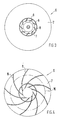
- Fig. 3 shows the impeller 6 from the suction side.
- the blades 8 on the lower part 7 can be seen through the opening 10 in the cover 2.
- Fig. 4 again shows that the blades are 8 circular sections.
- the base points of the radius of all circular sections lie on the circle 16.
- the diameter of the circle 16 is 98 mm.
Landscapes
- Engineering & Computer Science (AREA)
- Mechanical Engineering (AREA)
- General Engineering & Computer Science (AREA)
- Structures Of Non-Positive Displacement Pumps (AREA)
Claims (5)
- Dispositif de transport d'un milieu gazeux dans un dispositif à grande résistance à l'écoulement,
caractérisé par un ventilateur radial présentant les attributs suivants:a) un carter (1) en forme de boisseau plat avec un contour intérieur (12) en forme de spirale,b) un couvercle sensiblement plan (2) avec une ouverture centrale de forme circulaire (10),c) un rotor fermé (6) dont le diamètre vaut plus de dix fois sa largeur (c) de sortie du flux,d) le rotor (6) est constitué d'une partie inférieure (7), sensiblement plane, d'une pluralité de pales (8) qui sont incurvées vers l'arrière, présentent la forme d'une portion de cercle dont la largeur à la périphérie du rotor est inférieure à ce qu'elle est à son extrémité intérieure, et un couvercle (9) de forme circulaire, en forme d'assiette plate, avec une ouverture centrale de forme circulaire,e) les pales (8) sont disposées dans le rotor (6) de façon que leur angle d'entrée (β1) et leur angle de sortie (β 2) présentent à peu près la même valeur,f) une fente en forme de coin dans la zone en languette (15) entre le rotor (6) et le contour intérieur (12) du carter (1). - Ventilateur radial selon la revendication 1,
caractérisé par le fait que la longueur des pales (8) est supérieure à la partie inférieure (7) qu'au couvercle (9). - Ventilateur radial selon les revendications 1 et 2,
caractérisé par le fait que les angles d'entrée et de sortie (β1, β2) des pales (8) présentent une valeur comprise entre 45 et 50 degrés. - Ventilateur radial selon les revendications 1 à 3,
caractérisé par le fait que l'endroit de la plus petite distance entre le rotor (6) et le contour intérieur (12) du carter (1) est décalé par rapport à la zone en languette (15) dans le sens de rotation du rotor (6) et s'étend à peu près sur un quart de la périphérie du carter (entre A et B). - Ventilateur radial selon la revendication 1 à 4,
caractérisé par le fait que la plus petite distance entre la périphérie du rotor et le contour intérieur (12) du carter (1) vaut entre 4 et 8% du rayon du rotor.
Applications Claiming Priority (2)
| Application Number | Priority Date | Filing Date | Title |
|---|---|---|---|
| DE3924281 | 1989-07-22 | ||
| DE3924281A DE3924281A1 (de) | 1989-07-22 | 1989-07-22 | Vorrichtung zum foerdern eines gasfoermigen mediums |
Publications (3)
| Publication Number | Publication Date |
|---|---|
| EP0410271A2 EP0410271A2 (fr) | 1991-01-30 |
| EP0410271A3 EP0410271A3 (en) | 1991-08-07 |
| EP0410271B1 true EP0410271B1 (fr) | 1994-09-21 |
Family
ID=6385604
Family Applications (1)
| Application Number | Title | Priority Date | Filing Date |
|---|---|---|---|
| EP90113649A Expired - Lifetime EP0410271B1 (fr) | 1989-07-22 | 1990-07-17 | Dispositif de transport de milieu gazeux |
Country Status (3)
| Country | Link |
|---|---|
| EP (1) | EP0410271B1 (fr) |
| JP (1) | JPH0357899A (fr) |
| DE (2) | DE3924281A1 (fr) |
Cited By (1)
| Publication number | Priority date | Publication date | Assignee | Title |
|---|---|---|---|---|
| EP2196679A2 (fr) | 2004-07-31 | 2010-06-16 | ebm-papst Landshut GmbH | Roue pour un ventilateur radiale |
Families Citing this family (13)
| Publication number | Priority date | Publication date | Assignee | Title |
|---|---|---|---|---|
| EP0516073A1 (fr) * | 1991-05-29 | 1992-12-02 | Alcatel SEL Aktiengesellschaft | Dispositif de transport d'un médium gazeux |
| DE4141360A1 (de) * | 1991-12-14 | 1993-06-17 | Sel Alcatel Ag | Radialgeblaese zum foerdern eines brennbaren gasgemisches |
| DE4141359A1 (de) * | 1991-12-14 | 1993-06-17 | Sel Alcatel Ag | Geblaeserad fuer radialgeblaese |
| DE4141362C2 (de) * | 1991-12-14 | 2002-10-24 | Motoren Ventilatoren Gmbh | Radialgebläse mit Drosselvorrichtung |
| DE4242474A1 (de) * | 1992-12-16 | 1994-06-23 | Sel Alcatel Ag | Vorrichtung zum Fördern eines gasförmigen Mediums |
| DE4318580A1 (de) * | 1993-06-04 | 1994-12-08 | Sel Alcatel Ag | Radialgebläse |
| DE19516515A1 (de) * | 1995-05-05 | 1996-11-07 | Sel Alcatel Ag | Radialgebläse |
| DE19602368A1 (de) * | 1996-01-24 | 1997-07-31 | Sel Alcatel Ag | Radialgebläse |
| DE20012654U1 (de) * | 2000-07-19 | 2000-09-21 | MAP Medizintechnik für Arzt und Patient GmbH & Co. KG, 82152 Planegg | Vorrichtung zur Zufuhr eines Atemgases |
| DE202005004180U1 (de) * | 2005-03-14 | 2006-07-27 | Ebm-Papst Landshut Gmbh | Radialgebläse |
| EP2357365B1 (fr) * | 2010-02-01 | 2016-11-16 | Brink Climate Systems B.V. | Système de mouvement d'air |
| CN103711713B (zh) * | 2012-09-28 | 2016-08-24 | 昆山广兴电子有限公司 | 离心式散热扇 |
| EP3530956B1 (fr) * | 2018-02-26 | 2021-09-22 | Honeywell Technologies Sarl | Roue à aubes pour soufflante radiale et appareil à brûleur à gaz |
Family Cites Families (5)
| Publication number | Priority date | Publication date | Assignee | Title |
|---|---|---|---|---|
| CH301116A (de) * | 1952-05-27 | 1954-08-31 | Ag Hch Bertrams | Ventilator-Druckgehäuse. |
| DE1204774B (de) * | 1954-01-27 | 1965-11-11 | Bruno Eck Dr Ing | Radialgeblaese zur Foerderung stark staubhaltiger Gase |
| FR1396805A (fr) * | 1964-05-28 | 1965-04-23 | Svenska Flaektfabriken Ab | Carter pour ventilateur centrifuge |
| GB2055969B (en) * | 1979-07-19 | 1983-11-16 | Sgm Co Inc | Low noise centrifugal blower |
| DE3700230A1 (de) * | 1987-01-07 | 1988-07-21 | Hauni Werke Koerber & Co Kg | Luefterrad |
-
1989
- 1989-07-22 DE DE3924281A patent/DE3924281A1/de not_active Withdrawn
-
1990
- 1990-07-17 EP EP90113649A patent/EP0410271B1/fr not_active Expired - Lifetime
- 1990-07-17 DE DE59007207T patent/DE59007207D1/de not_active Expired - Lifetime
- 1990-07-20 JP JP2190919A patent/JPH0357899A/ja active Pending
Cited By (3)
| Publication number | Priority date | Publication date | Assignee | Title |
|---|---|---|---|---|
| EP2196679A2 (fr) | 2004-07-31 | 2010-06-16 | ebm-papst Landshut GmbH | Roue pour un ventilateur radiale |
| US7794206B2 (en) | 2004-07-31 | 2010-09-14 | Emb-Papst Landshut Gmbh | Radial fan impeller |
| US8109731B2 (en) | 2004-07-31 | 2012-02-07 | Ebm-Papst Landshut Gmbh | Radial fan impeller |
Also Published As
| Publication number | Publication date |
|---|---|
| JPH0357899A (ja) | 1991-03-13 |
| EP0410271A3 (en) | 1991-08-07 |
| DE3924281A1 (de) | 1991-01-31 |
| EP0410271A2 (fr) | 1991-01-30 |
| DE59007207D1 (de) | 1994-10-27 |
Similar Documents
| Publication | Publication Date | Title |
|---|---|---|
| EP0410271B1 (fr) | Dispositif de transport de milieu gazeux | |
| DE2940773C2 (de) | Hochleistungs-Radialventilator | |
| EP0112932B1 (fr) | Ventilateur radial avec des aubes profilées courbées en arrière | |
| DE2551614C2 (de) | Axial kurzer Axialventilator | |
| DE2940650A1 (de) | Axialventilator | |
| DE2950060C2 (fr) | ||
| EP0627561A1 (fr) | Soufflante radial | |
| DE1503704C3 (de) | Schaufelkranz fuer ein lauf und oder leitrad einer turbomolekularpumpe | |
| EP0166174A1 (fr) | Ventilateur radial | |
| DE1403474A1 (de) | Zentrifugalgehaeuse fuer Ventilatoren | |
| DE3310376C2 (fr) | ||
| DE4130901A1 (de) | Geblaese | |
| CH684763A5 (de) | Dunstabzugshaube. | |
| DE20317171U1 (de) | Lüftergehäuse | |
| DE2136369A1 (de) | Waermeaustauscheraggregat, insbesondere fuer raumklimageraete | |
| EP0074514B1 (fr) | Arrangement d'un dispositif de refroidissement et d'un moteur avec un ventilateur fixé sur son arbre, notamment pour une installation à compresseur à vis | |
| DE2001395C3 (fr) | ||
| DE2015737C3 (de) | Vorrichtung zur Agglomeration und Niederschlagung von Schwebestoffen aus Gasen und Dämpfen und/oder zur Absorption von Gasbestandteilen | |
| EP0070423B1 (fr) | Refroidissement d'un moteur électrique entraînant un ventilateur axial | |
| DE3343752C2 (fr) | ||
| EP0228739A2 (fr) | Soufflante avec un boîtier substantiellement de forme carrée | |
| DE19709193A1 (de) | Radialventilator | |
| DE1628336A1 (de) | Zentrifugalgeblaese mit Trommellaufrad | |
| DE9100671U1 (de) | Ventilator, insbesondere Rohr- oder Kanalventilator | |
| DE9305528U1 (de) | Spiralgebläse |
Legal Events
| Date | Code | Title | Description |
|---|---|---|---|
| PUAI | Public reference made under article 153(3) epc to a published international application that has entered the european phase |
Free format text: ORIGINAL CODE: 0009012 |
|
| AK | Designated contracting states |
Kind code of ref document: A2 Designated state(s): DE FR GB IT NL |
|
| PUAL | Search report despatched |
Free format text: ORIGINAL CODE: 0009013 |
|
| AK | Designated contracting states |
Kind code of ref document: A3 Designated state(s): DE FR GB IT NL |
|
| 17P | Request for examination filed |
Effective date: 19911212 |
|
| RAP3 | Party data changed (applicant data changed or rights of an application transferred) |
Owner name: ALCATEL SEL AKTIENGESELLSCHAFT |
|
| 17Q | First examination report despatched |
Effective date: 19921216 |
|
| GRAA | (expected) grant |
Free format text: ORIGINAL CODE: 0009210 |
|
| AK | Designated contracting states |
Kind code of ref document: B1 Designated state(s): DE FR GB IT NL |
|
| REF | Corresponds to: |
Ref document number: 59007207 Country of ref document: DE Date of ref document: 19941027 |
|
| GBT | Gb: translation of ep patent filed (gb section 77(6)(a)/1977) |
Effective date: 19941018 |
|
| ITF | It: translation for a ep patent filed | ||
| ET | Fr: translation filed | ||
| PLBI | Opposition filed |
Free format text: ORIGINAL CODE: 0009260 |
|
| 26 | Opposition filed |
Opponent name: EBM ELEKTROBAU MULFINGEN GMBH & CO. Effective date: 19950617 |
|
| NLR1 | Nl: opposition has been filed with the epo |
Opponent name: EBM ELEKTROBAU MULFINGEN GMBH & CO. |
|
| PLBO | Opposition rejected |
Free format text: ORIGINAL CODE: EPIDOS REJO |
|
| PLBN | Opposition rejected |
Free format text: ORIGINAL CODE: 0009273 |
|
| STAA | Information on the status of an ep patent application or granted ep patent |
Free format text: STATUS: OPPOSITION REJECTED |
|
| 27O | Opposition rejected |
Effective date: 19971124 |
|
| NLR2 | Nl: decision of opposition | ||
| NLS | Nl: assignments of ep-patents |
Owner name: MOTOREN VENTILATOREN LANDSHUT GMBH |
|
| REG | Reference to a national code |
Ref country code: GB Ref legal event code: 732E |
|
| REG | Reference to a national code |
Ref country code: FR Ref legal event code: TP |
|
| REG | Reference to a national code |
Ref country code: GB Ref legal event code: IF02 |
|
| PGFP | Annual fee paid to national office [announced via postgrant information from national office to epo] |
Ref country code: FR Payment date: 20090716 Year of fee payment: 20 |
|
| PGFP | Annual fee paid to national office [announced via postgrant information from national office to epo] |
Ref country code: NL Payment date: 20090730 Year of fee payment: 20 Ref country code: GB Payment date: 20090720 Year of fee payment: 20 |
|
| PGFP | Annual fee paid to national office [announced via postgrant information from national office to epo] |
Ref country code: DE Payment date: 20090928 Year of fee payment: 20 |
|
| PGFP | Annual fee paid to national office [announced via postgrant information from national office to epo] |
Ref country code: IT Payment date: 20090723 Year of fee payment: 20 |
|
| REG | Reference to a national code |
Ref country code: NL Ref legal event code: V4 Effective date: 20100717 |
|
| REG | Reference to a national code |
Ref country code: GB Ref legal event code: PE20 Expiry date: 20100716 |
|
| PG25 | Lapsed in a contracting state [announced via postgrant information from national office to epo] |
Ref country code: NL Free format text: LAPSE BECAUSE OF EXPIRATION OF PROTECTION Effective date: 20100717 |
|
| PG25 | Lapsed in a contracting state [announced via postgrant information from national office to epo] |
Ref country code: GB Free format text: LAPSE BECAUSE OF EXPIRATION OF PROTECTION Effective date: 20100716 |
|
| PG25 | Lapsed in a contracting state [announced via postgrant information from national office to epo] |
Ref country code: DE Free format text: LAPSE BECAUSE OF EXPIRATION OF PROTECTION Effective date: 20100717 |