EP0410294B1 - Verfahren und Vorrichtung zur Wärmebehandlung von Metallband - Google Patents
Verfahren und Vorrichtung zur Wärmebehandlung von Metallband Download PDFInfo
- Publication number
- EP0410294B1 EP0410294B1 EP90113801A EP90113801A EP0410294B1 EP 0410294 B1 EP0410294 B1 EP 0410294B1 EP 90113801 A EP90113801 A EP 90113801A EP 90113801 A EP90113801 A EP 90113801A EP 0410294 B1 EP0410294 B1 EP 0410294B1
- Authority
- EP
- European Patent Office
- Prior art keywords
- enclosure
- strap
- strip
- gas
- treatment
- Prior art date
- Legal status (The legal status is an assumption and is not a legal conclusion. Google has not performed a legal analysis and makes no representation as to the accuracy of the status listed.)
- Expired - Lifetime
Links
- 238000000034 method Methods 0.000 title claims abstract description 19
- 239000002184 metal Substances 0.000 title claims abstract description 12
- 229910052751 metal Inorganic materials 0.000 title claims abstract description 12
- 238000000137 annealing Methods 0.000 title 1
- 238000009423 ventilation Methods 0.000 claims abstract description 8
- 238000010438 heat treatment Methods 0.000 claims description 24
- 238000011282 treatment Methods 0.000 claims description 17
- 229910000831 Steel Inorganic materials 0.000 claims description 12
- 239000012530 fluid Substances 0.000 claims description 12
- 239000010959 steel Substances 0.000 claims description 12
- 229910052799 carbon Inorganic materials 0.000 claims description 11
- OKTJSMMVPCPJKN-UHFFFAOYSA-N Carbon Chemical compound [C] OKTJSMMVPCPJKN-UHFFFAOYSA-N 0.000 claims description 4
- 229910001563 bainite Inorganic materials 0.000 claims description 4
- 229910000859 α-Fe Inorganic materials 0.000 claims description 4
- 229910000734 martensite Inorganic materials 0.000 claims description 3
- 239000007789 gas Substances 0.000 description 25
- 239000000203 mixture Substances 0.000 description 15
- 238000001816 cooling Methods 0.000 description 13
- 235000021183 entrée Nutrition 0.000 description 13
- IJGRMHOSHXDMSA-UHFFFAOYSA-N Atomic nitrogen Chemical compound N#N IJGRMHOSHXDMSA-UHFFFAOYSA-N 0.000 description 11
- 239000001257 hydrogen Substances 0.000 description 11
- 229910052739 hydrogen Inorganic materials 0.000 description 11
- VNWKTOKETHGBQD-UHFFFAOYSA-N methane Chemical compound C VNWKTOKETHGBQD-UHFFFAOYSA-N 0.000 description 10
- UFHFLCQGNIYNRP-UHFFFAOYSA-N Hydrogen Chemical compound [H][H] UFHFLCQGNIYNRP-UHFFFAOYSA-N 0.000 description 8
- XLYOFNOQVPJJNP-UHFFFAOYSA-N water Substances O XLYOFNOQVPJJNP-UHFFFAOYSA-N 0.000 description 8
- 238000009434 installation Methods 0.000 description 6
- 229910052757 nitrogen Inorganic materials 0.000 description 5
- 239000013529 heat transfer fluid Substances 0.000 description 4
- 150000002739 metals Chemical class 0.000 description 4
- 150000003839 salts Chemical class 0.000 description 4
- 240000008042 Zea mays Species 0.000 description 3
- 229910001566 austenite Inorganic materials 0.000 description 3
- 238000005255 carburizing Methods 0.000 description 3
- 150000002431 hydrogen Chemical class 0.000 description 3
- 238000012423 maintenance Methods 0.000 description 3
- 229910000975 Carbon steel Inorganic materials 0.000 description 2
- 239000010962 carbon steel Substances 0.000 description 2
- 239000000919 ceramic Substances 0.000 description 2
- 238000004140 cleaning Methods 0.000 description 2
- 239000001307 helium Substances 0.000 description 2
- 229910052734 helium Inorganic materials 0.000 description 2
- SWQJXJOGLNCZEY-UHFFFAOYSA-N helium atom Chemical compound [He] SWQJXJOGLNCZEY-UHFFFAOYSA-N 0.000 description 2
- 235000019362 perlite Nutrition 0.000 description 2
- 239000010451 perlite Substances 0.000 description 2
- 238000010583 slow cooling Methods 0.000 description 2
- 229910001209 Low-carbon steel Inorganic materials 0.000 description 1
- 241001080024 Telles Species 0.000 description 1
- HCHKCACWOHOZIP-UHFFFAOYSA-N Zinc Chemical compound [Zn] HCHKCACWOHOZIP-UHFFFAOYSA-N 0.000 description 1
- 238000005097 cold rolling Methods 0.000 description 1
- 239000004020 conductor Substances 0.000 description 1
- 239000004148 curcumin Substances 0.000 description 1
- 238000007598 dipping method Methods 0.000 description 1
- 238000004090 dissolution Methods 0.000 description 1
- 238000005246 galvanizing Methods 0.000 description 1
- 150000001247 metal acetylides Chemical class 0.000 description 1
- 239000007769 metal material Substances 0.000 description 1
- 229910052725 zinc Inorganic materials 0.000 description 1
- 239000011701 zinc Substances 0.000 description 1
Images



Classifications
-
- C—CHEMISTRY; METALLURGY
- C21—METALLURGY OF IRON
- C21D—MODIFYING THE PHYSICAL STRUCTURE OF FERROUS METALS; GENERAL DEVICES FOR HEAT TREATMENT OF FERROUS OR NON-FERROUS METALS OR ALLOYS; MAKING METAL MALLEABLE, e.g. BY DECARBURISATION OR TEMPERING
- C21D9/00—Heat treatment, e.g. annealing, hardening, quenching or tempering, adapted for particular articles; Furnaces therefor
- C21D9/52—Heat treatment, e.g. annealing, hardening, quenching or tempering, adapted for particular articles; Furnaces therefor for wires; for strips ; for rods of unlimited length
- C21D9/54—Furnaces for treating strips or wire
- C21D9/56—Continuous furnaces for strip or wire
- C21D9/561—Continuous furnaces for strip or wire with a controlled atmosphere or vacuum
-
- C—CHEMISTRY; METALLURGY
- C21—METALLURGY OF IRON
- C21D—MODIFYING THE PHYSICAL STRUCTURE OF FERROUS METALS; GENERAL DEVICES FOR HEAT TREATMENT OF FERROUS OR NON-FERROUS METALS OR ALLOYS; MAKING METAL MALLEABLE, e.g. BY DECARBURISATION OR TEMPERING
- C21D9/00—Heat treatment, e.g. annealing, hardening, quenching or tempering, adapted for particular articles; Furnaces therefor
- C21D9/52—Heat treatment, e.g. annealing, hardening, quenching or tempering, adapted for particular articles; Furnaces therefor for wires; for strips ; for rods of unlimited length
Definitions
- the invention relates to methods and devices for heat treating metal strips.
- French patent applications 88/00904 (FR-A-2 626 290) and 88/08425 (FR-A-2 632 973) describe methods and devices for carrying out pearlitization and austenitization treatments for threads metallic using tubes which contain gases practically without forced ventilation.
- the object of the invention is to generalize these advantages in the case of the heat treatment of metal strips.
- the invention relates to a method defined by main claim 1 for a method, and to a device defined by main claim 9 for a device.
- the strips treated according to the invention can be used for example to reinforce articles, in particular tire casings.
- strip should be taken in a general sense and includes any elongated element having a section perpendicular to its longitudinal direction which has a width significantly greater than its thickness, this element possibly having the shape of a substantially flat plate, or the shape of a profile.
- the ratio between the width of the strip and its thickness is at least equal to 10, the width of the strip being determined by following the surface of the strip, on its section perpendicular to its longitudinal direction.
- Figures 1 and 2 show a device 100 according to the invention for heat treatment of a metal strip 1.
- Figure 1 is a section of the device 100 made along the length of the strip and
- Figure 2 is a section of this device perpendicularly the length of the strip.
- the section in FIG. 1 is shown diagrammatically by the straight line segments I-I in FIG. 2, and the section in FIG. 2 is shown diagrammatically by the straight line segments II-II in FIG. 1.
- the device 100 making it possible to heat treat the strip 1, comprises an enclosure 2 containing a gas 3 practically devoid of forced ventilation.
- the device 100 includes means for scrolling the strip 1 in the enclosure 2, these means, not shown for the purpose of simplification being known means, for example rolls on which the strip 1 is wound at least one of these rollers being driven by a motor.
- the device 100 comprises a heat transfer fluid 4 circulating at the outside of the enclosure 2 in the hollow casing 5 surrounding the enclosure 2.
- the heat transfer fluid 4 arrives in the casing 5 through the pipe 6, and exits through the pipe 7, the circulation of the heat transfer fluid 4 being shown diagrammatically by the arrows F4 in Figure 1.
- the known means used to circulate the fluid 4 are not shown for the purpose of simplification, these means comprising for example a pump.
- the fluid 4 is for example water.
- heat transfer takes place between the strip 1 and the walls 2a of the enclosure 2, situated opposite the strip 1, by means of the gas 3.
- the heat transfer also takes place between the walls 2a and the fluid 4.
- the enclosure 2 and the casing 5 are produced with heat conducting materials, for example metallic materials, the transfer taking place from the strip 1 to the fluid 4, in the case of a strip cooling treatment 1.
- Guides 8 for example made of ceramic, guide the strip 1.
- K T J VS x E2 J being the adjustable thickness expressed in millimeters of the gas layer 3 between the strip 1 and the enclosure 2, E being the thickness of the strip expressed in millimeters, C being the thermal conductivity of the gas 3 determined at 600 ° C and expressed in watts.m ⁇ 1. . K ⁇ 1.
- J is at least equal to 0.2 mm and at most equal to 2 mm.
- K T is chosen as a function of the heat treatment to be carried out as described later.
- the width of the strip 1 is represented by L.
- the gas 3 can be of very diverse nature, for example hydrogen, nitrogen, helium, a mixture of hydrogen and nitrogen, hydrogen and methane, nitrogen and methane, helium and methane, hydrogen, nitrogen and methane.
- the strip 1 shown in Figures 1 and 2 has the shape of a flat plate, but the invention applies to cases where the strip has a shape which is not planar.
- the device 200 according to the invention, represented in FIG. 3, makes it possible to treat a strip 1 having a square shape, the enclosure 2 then being adapted so that there is a practically constant thickness J gas 3 between the strip 1 and the enclosure 2 which is for example itself arranged in the outer casing 5 of cylindrical shape.
- the thickness J can be adapted to the heat treatment to be carried out or to the strip.
- the thickness J is adjusted with the aid of rods 12 of semi-cylindrical section rotating around an axis 0, which modifies the distance between the walls 2a of the enclosure 2.
- Other means can be used, for example screws.
- Figures 3 and 4 are sections made respectively perpendicular to the longitudinal direction of the strip 1, and longitudinally.
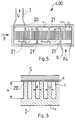
- FIG. 5 represents another device 400 according to the invention, FIG. 5 being a top view of the device, the casing 5 being assumed to be removed.
- Each wall 2a has fins 20 arranged on the side of the fluid 4 to improve the heat exchanges between the wall 2a and the fluid 4.
- These fins 20 have an orientation perpendicular to the longitudinal direction of the strip 1, shown diagrammatically by the arrow F.
- Deflectors 21 allow the fluid 4 to flow in a baffle between the inlet pipe 6 and the outlet pipe 7. This arrangement makes it possible to promote heat exchanges between the strip 1 and the fluid 4.
- FIG. 6 shows four fins 20 in section along a plane perpendicular to the strip 1, in the longitudinal direction of this strip. It can be seen in FIG. 6 that the fins 20 have a height H between the enclosure 2 and the seal 9, these fins being separated by the distance R, the thickness of the fins being represented by Ea.
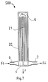
- FIG. 7 represents seen from above the circulation of the heat transfer fluid 4 of another device 500 according to the invention.
- This device 500 is similar to the device 400 with the difference that the fins 20 are oriented along the length of the strip, that is to say parallel to the arrow F, the supply 6 and the outlet 7 of the fluid 4 taking place on the same side of the device with respect to the direction of travel F.
- the fluid 4 flows parallel to the length of the strip but in opposite direction sections thanks to one / or more deflectors 21, also arranged in the direction of the length of the strip, only one of these deflectors 21 being shown in Figure 7 for the sake of simplification.
- the invention also relates to devices devoid of heat transfer fluids such as, for example, the device 600 shown in FIG. 8.
- the walls 2a of the enclosure 2 of this device 600 are formed by two ceramic plates 30 separated by the distance D. These plates 30 have grooves 31 in which electrical heating resistors 32 are arranged in contact with the plates 30.
- each plate 30 has a groove in which a resistor 32 is arranged, this resistor having the shape of a coil , as shown in Figure 9 which is a top view of a plate 30 with its resistor 32.
- This device 600 is used to heat the strip 1 or to prevent its cooling.
- All the strips treated are by way of example in the form of flat plates, that is to say that they have a section perpendicular to the longitudinal direction which has a rectangular shape.
- This example concerns the treatment of carbon steel with a martensitic structure, in accordance with patent FR 2 311 854.
- a strip of thickness E 100 "m and width L is used 300 mm obtained by cold rolling a strip 2 mm thick, the steel of which has the following composition: C: 0.085%; Mn: 0.3%; If: 0.05%; S: 0.024%; P: 0.024%; Cu: 0.056%; Cr: 0.05%; Ni: 0.025%; N: 0.003%; Total O: 0.0145%.
- Strip running speed 1 m / s.
- This example concerns the heating of a steel strip before galvanization by dipping in a bath of molten zinc.
- This preheating is carried out with a device 600 whose power nominal heating is 1300 kW.
- Strip running speed 0.2 m / s.
- Strip residence time 3.25 s.
- K T 3.81.
- Preferably, for preheating before galvanizing we have: 1 ⁇ K T ⁇ 10.
- This example describes a pearlitization treatment of a steel strip with a heating phase and two cooling phases.
- composition of the steel used is as follows: C: 0.80%; Mn: 0.69%; If: 0.21%; S: 0.025%; P: 0.018%; Al: 0.081%; Ca: 0.044%; Cr: 0.059%; Ni: 0.015%.
- the invention is not limited to the embodiments previously described.
- the invention covers the case where several strips are treated simultaneously.
Landscapes
- Chemical & Material Sciences (AREA)
- Engineering & Computer Science (AREA)
- Materials Engineering (AREA)
- Thermal Sciences (AREA)
- Crystallography & Structural Chemistry (AREA)
- Mechanical Engineering (AREA)
- Physics & Mathematics (AREA)
- Metallurgy (AREA)
- Organic Chemistry (AREA)
- Heat Treatment Of Strip Materials And Filament Materials (AREA)
- Filling Or Discharging Of Gas Storage Vessels (AREA)
- Heat Treatments In General, Especially Conveying And Cooling (AREA)
- Heat Treatment Of Sheet Steel (AREA)
- Heat Treatment Of Articles (AREA)
Claims (12)
- Verfahren zur Wärmebehandlung wenigstens eines Metallbandes mit der Form einer im wesentlichen ebenen Platte oder eines Profils, gemäß dem man das Band in ein Gehäuse eintreten läßt, dessen Wände parallel zu den Oberflächen des Bandes sind und das ein von erzwungener Ventilation praktisch freies Gas derart enthält, daß ein Wärmeübergang zwischen dem Band und den Wänden des Gehäuses mittels des im Gehäuse enthaltenen Gases erfolgt, und gemäß dem der Koeffizient KT durch die Beziehungen definiert wird:

wobei J die in mm ausgedrückte Dicke der Gasschicht zwischen dem Band und dem Gehäuse ist,
E die in mm ausgedrückte Dicke des Bandes ist, und
C die bei 600 °C bestimmte und in W.m⁻¹.°K⁻¹ ausgedrückte Wärmeleitfähigkeit ist. - Verfahren nach dem Anspruch 1,
dadurch gekennzeichnet,
daß man die Beziehung 0,2 mm ≦ J ≦ 2 mm hat. - Verfahren nach einem der Ansprüche 1 oder 2,
dadurch gekennzeichnet,
daß man eine Stahlbandbehandlung vornimmt. - Verfahren nach dem Anspruch 3,
dadurch gekennzeichnet,
daß man ein Stahlband mit zwei Phasen, Ferrit und Bainit, mit der Beziehung 4 ≦ KT ≦ 100 herstellt. - Verfahren nach dem Anspruch 3,
dadurch gekennzeichnet,
daß man ein Band martensitischen Gefüges mit der Beziehung 0,01 ≦ KT ≦ 0,1 behandelt. - Verfahren nach dem Anspruch 5,
dadurch gekennzeichnet,
daß man eine Zementierungsbehandlung zum Erhalten von 0,4 bis 0,9 % Kohlenstoff vornimmt. - Verfahren nach dem Anspruch 3,
dadurch gekennzeichnet,
daß man vor Durchführung einer Verzinkungsbehandlung des Bandes eine Vorerhitzung mit der Beziehung 1 ≦ KT ≦ 10 vornimmt. - Verfahren nach dem Anspruch 3,
dadurch gekennzeichnet,
daß man eine Perlitisierungsbehandlung mit 1 ≦ KT ≦ 8 vornimmt. - Vorrichtung zur Wärmebehandlung wenigstens eines Metallbandes mit der Form einer im wesentlichen ebenen Platte oder eines Profils, welche Vorrichtung die folgenden Merkmale aufweist:a) sie weist wenigstens ein Gehäuse, das ein von erzwungener Ventilation praktisch freies Gas enthält, und Mittel auf, die ermöglichen, wenigstens ein Band in das Gehäuse eintreten zu lassen;b) die Vorrichtung wird betrieben, so daß ein Wärmeübergang zwischen dem Band und den Wänden des Gehäuses mittels des im Gehäuse enthaltenen Gases erfolgt, wobei der Koeffizient KT durch die Beziehungen definiert wird:

wobei J die in mm ausgedrückte Dicke der Gasschicht zwischen dem Band und dem Gehäuse ist,
E die in mm ausgedrückte Dicke des Bandes ist, und
C die bei 600 °C bestimmte und in W.m⁻¹.°K⁻¹ ausgedruckte Wärmeleitfähigkeit ist;c) die Vorrichtung weist Mittel auf, die es ermöglichen, J variieren zu lassen. - Vorrichtung nach dem Anspruch 9,
dadurch gekennzeichnet
daß man 0,2 mm ≦ J ≦ 2 mm hat. - Vorrichtung nach irgendeinem der Ansprüche 9 oder 10, dadurch gekennzeichnet,
daß sie wenigstens einen elektrischen Widerstand im Kontakt mit einer Wand des Gehäuses aufweist. - Vorrichtung nach irgendeinem der Ansprüche 9 bis 11, dadurch gekennzeichnet,
daß sie Mittel aufweist, die ermöglichen, ein Wärmeübertragungsfluid an der Außenseite des Gehäuses zirkulieren zu lassen.
Applications Claiming Priority (2)
| Application Number | Priority Date | Filing Date | Title |
|---|---|---|---|
| FR8910323A FR2650295B1 (fr) | 1989-07-26 | 1989-07-26 | Procede et dispositif permettant de traiter thermiquement des feuillards metalliques |
| FR8910323 | 1989-07-26 |
Publications (2)
| Publication Number | Publication Date |
|---|---|
| EP0410294A1 EP0410294A1 (de) | 1991-01-30 |
| EP0410294B1 true EP0410294B1 (de) | 1995-03-01 |
Family
ID=9384332
Family Applications (1)
| Application Number | Title | Priority Date | Filing Date |
|---|---|---|---|
| EP90113801A Expired - Lifetime EP0410294B1 (de) | 1989-07-26 | 1990-07-19 | Verfahren und Vorrichtung zur Wärmebehandlung von Metallband |
Country Status (8)
| Country | Link |
|---|---|
| US (1) | US5089059A (de) |
| EP (1) | EP0410294B1 (de) |
| JP (1) | JPH0361331A (de) |
| AT (1) | ATE119211T1 (de) |
| CA (1) | CA2022042A1 (de) |
| DE (1) | DE69017296T2 (de) |
| ES (1) | ES2069637T3 (de) |
| FR (1) | FR2650295B1 (de) |
Families Citing this family (3)
| Publication number | Priority date | Publication date | Assignee | Title |
|---|---|---|---|---|
| US6355364B1 (en) | 1999-06-29 | 2002-03-12 | International Business Machines Corporation | Process of heat treating and annealing CIC and CIC created thereby |
| US20050123740A1 (en) * | 2000-03-22 | 2005-06-09 | Hume James M. | Liner for waste water system rehabilitation |
| JP5629992B2 (ja) * | 2009-08-08 | 2014-11-26 | 大同特殊鋼株式会社 | 金属ストリップの横型連続焼鈍炉 |
Family Cites Families (8)
| Publication number | Priority date | Publication date | Assignee | Title |
|---|---|---|---|---|
| DE1075136B (de) * | 1960-02-11 | Vacuumschmelze Aktiengesellschaft, Hanau | Durchlaufofen fur Tempera türen über 10000C zum Glühen von Werkstoffen in sehr reiner Schutzgasatmosphäre | |
| FR326005A (fr) * | 1902-10-18 | 1903-05-14 | Reid John Keith | Perfectionnements dans les systèmes de signaux |
| US1944743A (en) * | 1930-06-26 | 1934-01-23 | Gen Electric | Method for annealing steel |
| DE1811121A1 (de) * | 1968-11-27 | 1970-06-11 | Willi Vongehr | Ofen zum Blankgluehen von Draehten oder feinen Metallgeweben und Metalltuechern |
| DE2111631A1 (de) * | 1970-03-13 | 1972-03-30 | Pirelli | Vorrichtung zum Haerten von Stahldraht |
| US3950192A (en) * | 1974-10-30 | 1976-04-13 | Monsanto Company | Continuous carburizing method |
| FR2311854A1 (fr) * | 1975-05-21 | 1976-12-17 | Michelin & Cie | Toles d'acier et objets en tole d'acier a proprietes ameliorees et leur procede de fabrication |
| FR2626290B1 (fr) * | 1988-01-25 | 1990-06-01 | Michelin & Cie | Procedes et dispositifs permettant de traiter thermiquement des fils d'acier au carbone de facon a obtenir une structure perlitique fine |
-
1989
- 1989-07-26 FR FR8910323A patent/FR2650295B1/fr not_active Expired - Fee Related
-
1990
- 1990-07-19 ES ES90113801T patent/ES2069637T3/es not_active Expired - Lifetime
- 1990-07-19 DE DE69017296T patent/DE69017296T2/de not_active Expired - Fee Related
- 1990-07-19 EP EP90113801A patent/EP0410294B1/de not_active Expired - Lifetime
- 1990-07-19 AT AT90113801T patent/ATE119211T1/de not_active IP Right Cessation
- 1990-07-24 US US07/557,573 patent/US5089059A/en not_active Expired - Fee Related
- 1990-07-26 CA CA002022042A patent/CA2022042A1/fr not_active Abandoned
- 1990-07-26 JP JP2198967A patent/JPH0361331A/ja active Pending
Also Published As
| Publication number | Publication date |
|---|---|
| FR2650295B1 (fr) | 1994-04-01 |
| FR2650295A1 (fr) | 1991-02-01 |
| US5089059A (en) | 1992-02-18 |
| ATE119211T1 (de) | 1995-03-15 |
| CA2022042A1 (fr) | 1991-01-27 |
| JPH0361331A (ja) | 1991-03-18 |
| DE69017296D1 (de) | 1995-04-06 |
| DE69017296T2 (de) | 1995-06-29 |
| EP0410294A1 (de) | 1991-01-30 |
| ES2069637T3 (es) | 1995-05-16 |
Similar Documents
| Publication | Publication Date | Title |
|---|---|---|
| EP0326005B1 (de) | Verfahren und Vorrichtungen zur Wärmebehandlung von Kohlenstoffstahldrähten, um so ein feines perlitisches Gefüge zu bekommen | |
| EP0795616B1 (de) | Durchlaufglühverfahren von Metallband in verschiedenen Schutzgasen und Vorrichtung | |
| JP2919962B2 (ja) | 物体の連続/断続的被覆を行うためのハウジングと設備 | |
| EP1405926A1 (de) | Vorrichtung zum Induktionshärten, insbesondere zum Herstellen von Aufhängungselementen | |
| FR3014449A1 (fr) | Appareil et procede de chauffage par induction pour section de recuit apres galvanisation. | |
| EP0979879B1 (de) | Verfahren für die Feuerverzinkung eines Metallbandes | |
| EP0410294A1 (de) | Verfahren und Vorrichtung zur Wärmebehandlung von Metallband | |
| CA1303946C (fr) | Procede et dispositif pour traiter thermiquement un fil d'acier | |
| EP0005389B1 (de) | Anlage zum Biegen und Härten von Glasscheiben | |
| EP0126696B1 (de) | Verfahren zur kontinuierlichen Herstellung von überaltertem Stahlband, beschichtet mit Zink oder mit einer Aluminium-Zink-Legierung | |
| FR2460333A1 (fr) | Procede et appareil pour refroidir des bandes d'acier au cours d'un traitement de recuit en continu | |
| FR2462647A1 (fr) | Procede de fabrication de tubes, tubes obtenus par ce procede et leur utilisation comme conduites d'eau | |
| FR2576323A1 (fr) | Procede de traitement de profils conducteurs, notamment metalliques, installation pour sa mise en oeuvre et profils traites ainsi obtenus | |
| FR2711147A1 (fr) | Procédé de fabrication d'un produit plat en alliage de zirconium comprenant un réchauffage dans le domaine béta par infrarouges. | |
| FR2632973A1 (fr) | Procedes et dispositifs pour obtenir une structure d'austenite homogene | |
| FR2673198A1 (fr) | Procede de fabrication d'une bande ou tole en zircaloy 2 ou 4 et produit obtenu. | |
| BE825565A (fr) | Procede et dispositif de patentage de fils d'acier. | |
| EP1669465B1 (de) | Walz- und Glühverfahren für die Herstellung eines Bandes aus nichtrostendem Stahl und Vorrichtung zur Durchführung des Verfahrens | |
| EP0418166A1 (de) | Kühlvorrichtung mit Kontaktrollen zum kontinuierlichen Abschrecken von vorgewärmtem Stahlband | |
| JP3227044B2 (ja) | めっき装置 | |
| GB1576933A (en) | Process and apparatus for coating metallic wires | |
| EP0062239A1 (de) | Verfahren und Vorrichtung zum Durchlaufglühen und -abschrecken von länglichen Gegenständen aus Sonderstählen | |
| RU2048594C1 (ru) | Способ нанесения металлических покрытий на внутреннюю и внешнюю поверхности труб и устройство для его осуществления | |
| JPS56114504A (en) | Method and apparatus for continuously manufacturing heat treated tapered wire rod | |
| EP0471679A1 (de) | Verhinderung des bleiziehens beim patentieren. |
Legal Events
| Date | Code | Title | Description |
|---|---|---|---|
| PUAI | Public reference made under article 153(3) epc to a published international application that has entered the european phase |
Free format text: ORIGINAL CODE: 0009012 |
|
| 17P | Request for examination filed |
Effective date: 19900719 |
|
| AK | Designated contracting states |
Kind code of ref document: A1 Designated state(s): AT BE CH DE DK ES FR GB GR IT LI LU NL SE |
|
| 17Q | First examination report despatched |
Effective date: 19930202 |
|
| GRAA | (expected) grant |
Free format text: ORIGINAL CODE: 0009210 |
|
| AK | Designated contracting states |
Kind code of ref document: B1 Designated state(s): AT BE CH DE DK ES FR GB GR IT LI LU NL SE |
|
| PG25 | Lapsed in a contracting state [announced via postgrant information from national office to epo] |
Ref country code: GR Free format text: LAPSE BECAUSE OF FAILURE TO SUBMIT A TRANSLATION OF THE DESCRIPTION OR TO PAY THE FEE WITHIN THE PRESCRIBED TIME-LIMIT Effective date: 19950301 Ref country code: DK Effective date: 19950301 Ref country code: AT Effective date: 19950301 |
|
| REF | Corresponds to: |
Ref document number: 119211 Country of ref document: AT Date of ref document: 19950315 Kind code of ref document: T |
|
| ITF | It: translation for a ep patent filed | ||
| REF | Corresponds to: |
Ref document number: 69017296 Country of ref document: DE Date of ref document: 19950406 |
|
| GBT | Gb: translation of ep patent filed (gb section 77(6)(a)/1977) |
Effective date: 19950410 |
|
| REG | Reference to a national code |
Ref country code: ES Ref legal event code: FG2A Ref document number: 2069637 Country of ref document: ES Kind code of ref document: T3 |
|
| PG25 | Lapsed in a contracting state [announced via postgrant information from national office to epo] |
Ref country code: SE Effective date: 19950601 |
|
| PG25 | Lapsed in a contracting state [announced via postgrant information from national office to epo] |
Ref country code: LI Effective date: 19950731 Ref country code: CH Effective date: 19950731 |
|
| PLBE | No opposition filed within time limit |
Free format text: ORIGINAL CODE: 0009261 |
|
| STAA | Information on the status of an ep patent application or granted ep patent |
Free format text: STATUS: NO OPPOSITION FILED WITHIN TIME LIMIT |
|
| 26N | No opposition filed | ||
| REG | Reference to a national code |
Ref country code: CH Ref legal event code: PL |
|
| PGFP | Annual fee paid to national office [announced via postgrant information from national office to epo] |
Ref country code: LU Payment date: 19980210 Year of fee payment: 9 |
|
| PGFP | Annual fee paid to national office [announced via postgrant information from national office to epo] |
Ref country code: NL Payment date: 19980716 Year of fee payment: 9 |
|
| PGFP | Annual fee paid to national office [announced via postgrant information from national office to epo] |
Ref country code: ES Payment date: 19980724 Year of fee payment: 9 |
|
| PGFP | Annual fee paid to national office [announced via postgrant information from national office to epo] |
Ref country code: BE Payment date: 19980727 Year of fee payment: 9 |
|
| PG25 | Lapsed in a contracting state [announced via postgrant information from national office to epo] |
Ref country code: LU Free format text: LAPSE BECAUSE OF NON-PAYMENT OF DUE FEES Effective date: 19990719 |
|
| PG25 | Lapsed in a contracting state [announced via postgrant information from national office to epo] |
Ref country code: ES Free format text: LAPSE BECAUSE OF NON-PAYMENT OF DUE FEES Effective date: 19990720 |
|
| PG25 | Lapsed in a contracting state [announced via postgrant information from national office to epo] |
Ref country code: BE Free format text: LAPSE BECAUSE OF NON-PAYMENT OF DUE FEES Effective date: 19990731 |
|
| BERE | Be: lapsed |
Owner name: CIE GENERALE DES ETS MICHELIN - MICHELIN & CIE Effective date: 19990731 |
|
| PG25 | Lapsed in a contracting state [announced via postgrant information from national office to epo] |
Ref country code: NL Free format text: LAPSE BECAUSE OF NON-PAYMENT OF DUE FEES Effective date: 20000201 |
|
| NLV4 | Nl: lapsed or anulled due to non-payment of the annual fee |
Effective date: 20000201 |
|
| REG | Reference to a national code |
Ref country code: GB Ref legal event code: IF02 |
|
| PGFP | Annual fee paid to national office [announced via postgrant information from national office to epo] |
Ref country code: GB Payment date: 20020628 Year of fee payment: 13 |
|
| PGFP | Annual fee paid to national office [announced via postgrant information from national office to epo] |
Ref country code: FR Payment date: 20020711 Year of fee payment: 13 Ref country code: DE Payment date: 20020711 Year of fee payment: 13 |
|
| PG25 | Lapsed in a contracting state [announced via postgrant information from national office to epo] |
Ref country code: GB Free format text: LAPSE BECAUSE OF NON-PAYMENT OF DUE FEES Effective date: 20030719 |
|
| PG25 | Lapsed in a contracting state [announced via postgrant information from national office to epo] |
Ref country code: DE Free format text: LAPSE BECAUSE OF NON-PAYMENT OF DUE FEES Effective date: 20040203 |
|
| GBPC | Gb: european patent ceased through non-payment of renewal fee |
Effective date: 20030719 |
|
| PG25 | Lapsed in a contracting state [announced via postgrant information from national office to epo] |
Ref country code: FR Free format text: LAPSE BECAUSE OF NON-PAYMENT OF DUE FEES Effective date: 20040331 |
|
| REG | Reference to a national code |
Ref country code: ES Ref legal event code: FD2A Effective date: 20000810 |
|
| REG | Reference to a national code |
Ref country code: FR Ref legal event code: ST |
|
| PG25 | Lapsed in a contracting state [announced via postgrant information from national office to epo] |
Ref country code: IT Free format text: LAPSE BECAUSE OF NON-PAYMENT OF DUE FEES Effective date: 20050719 |