EP0410505A2 - Capteur à fibres optiques basé sur l'excitation des plasmons de surface - Google Patents
Capteur à fibres optiques basé sur l'excitation des plasmons de surface Download PDFInfo
- Publication number
- EP0410505A2 EP0410505A2 EP90201914A EP90201914A EP0410505A2 EP 0410505 A2 EP0410505 A2 EP 0410505A2 EP 90201914 A EP90201914 A EP 90201914A EP 90201914 A EP90201914 A EP 90201914A EP 0410505 A2 EP0410505 A2 EP 0410505A2
- Authority
- EP
- European Patent Office
- Prior art keywords
- optical fiber
- excitation
- surface plasma
- optical
- sensor based
- Prior art date
- Legal status (The legal status is an assumption and is not a legal conclusion. Google has not performed a legal analysis and makes no representation as to the accuracy of the status listed.)
- Withdrawn
Links
Images


Classifications
-
- G—PHYSICS
- G01—MEASURING; TESTING
- G01N—INVESTIGATING OR ANALYSING MATERIALS BY DETERMINING THEIR CHEMICAL OR PHYSICAL PROPERTIES
- G01N21/00—Investigating or analysing materials by the use of optical means, i.e. using sub-millimetre waves, infrared, visible or ultraviolet light
- G01N21/17—Systems in which incident light is modified in accordance with the properties of the material investigated
- G01N21/55—Specular reflectivity
- G01N21/552—Attenuated total reflection
- G01N21/553—Attenuated total reflection and using surface plasmons
-
- G—PHYSICS
- G01—MEASURING; TESTING
- G01N—INVESTIGATING OR ANALYSING MATERIALS BY DETERMINING THEIR CHEMICAL OR PHYSICAL PROPERTIES
- G01N2201/00—Features of devices classified in G01N21/00
- G01N2201/08—Optical fibres; light guides
Definitions
- the following invention consists of an optical fiber sensor based on the excitation of surface plasma, which is useful for use in chemical detection, biochemical analysis, etc.
- the device is based on the resonant optical excitation of surface plasma on the interface existing between a thin metal film and a controlled outer dielectric medium.
- the object of the patent is to effect a small portable sensor device, without any moveable pieces and which by means of optical fibers permits centralized remote control thereof.
- SPO Surface Plasma Oscillation
- the wave vector of the plasma which depends on the refraction indexes of the three medium in contact, determines the incidence angle for which the resonant optical excitation is given.
- the reflexion coefficient given by has an abrupt minimum, in function of the incidence angle, as well as of the refraction indexes and, particularly, of the refraction index of the outer medium.
- the device consists of a sensor head, a light emission and detection system an optical fiber system that connects the sensor head to the light emission and detection systems.
- the sensor head consists of a transparent geometric figure, in which one of its surfaces is a cylindric mirror, whose axis is in the plane of said geometric figure; upon one flat surface perpendicular to the cylindric mirror , a flat parallel sheet of a transparent material similar to the one that geometric figure is made out of, and upon which a thin metal layer has been deposited is adhered by means of a refraction index adapter liquid (for example, for BK7 glass, D.P.X.
- a refraction index adapter liquid for example, for BK7 glass, D.P.X.
- the end of the incident optical fiber is situated in the axis of the cylindric mirror, in such a way that the image of the end of the fiber through the metal film and the cylindric mirror is an interval of the axis itself of the cylinder. In a point of this interval, the end of the detection optical fiber is positioned; the incidence angle is determined by this fiber, through the two cited reflexions.
- the thickness of the sensor head is such that it does not limit the outlet beam of the incident optical fiber. Between the detection optical fiber and the sensor head, a polarizer which only selects light with polarization p is placed.
- the object of this patent is to avoid the inconveniences of the discrete devices made up to now, making a small portable sensor device, without moveable pieces and which by means of optical fibers permits centralized remote control thereof.
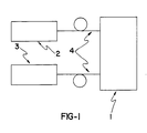
- the device object of the invention is comprised of a sensor head (1), a light emission (2) and light detection (3) system and an optical fiber system (4) that connects the sensor head with the light emission and light detection systems.
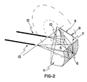
- the sensor head consists of a transparent geometric figure (5) in which one of its surfaces (6) is a cylindric mirror, whose axis is in the plane of the geometric figure; upon the flat surface (7) and perpendicular to the cylindric mirror, a flat-parallel sheet (8) of a transparent material similar to that forming the geometric figure (5) and upon which a thin metal layer (9) has been deposited is adhered by means of a refraction index adapter liquid (for example, for BK7 glass, the B.P.X.
- a refraction index adapter liquid for example, for BK7 glass, the B.P.X.
- the end of the incident optical fiber (12) is situated in the axis of the cylindric mirror (6), in such a way that the image of the end of the fiber through the metal film (9) and the cylindric mirror (6) is an interval of the axis itself of the cylinder. In a point of this interval, the end of the detection optical fiber (13) is positioned, the incidence angle is determined by this fiber, through the two cited reflexions.
- the thickness of the geometric figure (5) is such that it does not limit the outlet beam of the incident optical fiber.
- optical fibers are connected to the sensor head by both connectors which can be of permanent or removeable connection.
- the types of optical fiber that can be used in this device are both multimode optical fibers, as well as monomode optical fibers, either of a high silica content or else of any other material (for example, plastic material.)
- the light emission system can use a LED (Luminiscent Electro Diode or Light Emission Diode) or a semiconductor laser emitting in any of the wave lengths used in optical fiber transmission windows, in other words, around 850 nm, 1,300 nm or 1,550 nm.
- the detection system uses conventionally used detectors and amplifiers used in optical fiber transmission systems.
- the optical power transmitted through the detection optical fiber is a function of the refraction index of the outer medium in contact with the metal film.
- FIG 3 the standardized theoretical value of the optical power measured in terms of the refraction index of the outer medium, is shown.
- the position of the detection optical fiber is used only to select the operating point of the sensor head.
- the sensor device can be provided with a dynamic self-gaging signal by placing another optical fiber next to the detection optical fiber with the polarizer selecting the polarization s and therefore providing a reference signal, or else using as an outlet optical fiber a maintained polarization fiber; in this case, the polarizer is not required, since both polarizations are separated in the propagation through the fiber itself and they can be obtained invidudually in the detection stage.
- the sensor device can be used in multiple uses, in the field of chemistry or biochemistry, to detect species that are present in liquid or gas solutions.
- the metal film can be coated with layers that cover the metal film with layers that include immobilized compounds, specifically sensitive to the species to be detected (for example enzymes and coenzymes, antigens and antibodies, etc.)
- the sensitivity and dynamic range of the sensor can be optimized for the specific use of the same, coating the metal film with a transparent dielectric material, with adequate refraction index and thickness. Besides, this layer is also a protection against outer physical and chemical agents which can harm or affect the performance of the sensor.
- the senor has been oriented towards chemical or biochemical uses, it may also be used as an optical sensor to detect the variation of any physical or chemical parameter, which affects the optical properties of the outer medium to be controlled.
Landscapes
- General Health & Medical Sciences (AREA)
- Health & Medical Sciences (AREA)
- Life Sciences & Earth Sciences (AREA)
- Chemical & Material Sciences (AREA)
- Analytical Chemistry (AREA)
- Biochemistry (AREA)
- Physics & Mathematics (AREA)
- General Physics & Mathematics (AREA)
- Immunology (AREA)
- Pathology (AREA)
- Investigating Or Analysing Materials By Optical Means (AREA)
- Investigating, Analyzing Materials By Fluorescence Or Luminescence (AREA)
- Optical Transform (AREA)
Applications Claiming Priority (2)
| Application Number | Priority Date | Filing Date | Title |
|---|---|---|---|
| ES8902630A ES2015430A6 (es) | 1989-07-25 | 1989-07-25 | Sensor de fibra optica basado en la excitacion de plasmones superficiales. |
| ES8902630 | 1989-07-25 |
Publications (2)
| Publication Number | Publication Date |
|---|---|
| EP0410505A2 true EP0410505A2 (fr) | 1991-01-30 |
| EP0410505A3 EP0410505A3 (en) | 1991-05-22 |
Family
ID=8263268
Family Applications (1)
| Application Number | Title | Priority Date | Filing Date |
|---|---|---|---|
| EP19900201914 Withdrawn EP0410505A3 (en) | 1989-07-25 | 1990-07-13 | Optical fiber sensor based on the excitation of surface plasma |
Country Status (4)
| Country | Link |
|---|---|
| US (1) | US5245410A (fr) |
| EP (1) | EP0410505A3 (fr) |
| JP (1) | JPH0359439A (fr) |
| ES (1) | ES2015430A6 (fr) |
Cited By (2)
| Publication number | Priority date | Publication date | Assignee | Title |
|---|---|---|---|---|
| DE4305830C1 (de) * | 1993-02-26 | 1994-08-18 | Claus Dr Rer Nat Renschen | SPR-Sensor |
| DE4424628A1 (de) * | 1994-07-13 | 1996-01-18 | Matthias Dipl Ing Lau | Verfahren und Anordnung zur Brechzahlmessung verschiedener Medien |
Families Citing this family (9)
| Publication number | Priority date | Publication date | Assignee | Title |
|---|---|---|---|---|
| GB9120000D0 (en) * | 1991-09-19 | 1991-11-06 | British Gas Plc | Optical sensing |
| US5606633A (en) * | 1995-06-26 | 1997-02-25 | American Research Corporation Of Virginia | Chemical detector employing surface plasmon resonance excited using an optical waveguide configured as an asymmetric waveguide coupler |
| US7244622B2 (en) * | 1996-04-03 | 2007-07-17 | Applera Corporation | Device and method for multiple analyte detection |
| WO1999001737A2 (fr) * | 1997-06-10 | 1999-01-14 | Calspan Corporation | Detection des matieres d'un agent chimique par utilisation d'un polymere sorbant et sonde a fluorescence |
| US6121755A (en) * | 1999-06-03 | 2000-09-19 | Illinois Tool Works Inc. | Optical-electronic battery indicator |
| DE10247241A1 (de) * | 2002-10-10 | 2004-04-22 | Basf Ag | Superabsorbierender Schaum, Verfahren zu seiner Herstellung und seine Verwendung |
| JP4505279B2 (ja) * | 2004-08-02 | 2010-07-21 | 富士フイルム株式会社 | 試料分析用測定装置および測定方法 |
| SE0402292D0 (sv) * | 2004-09-23 | 2004-09-23 | Goeran Palmskog | Arrangement for determining concentration of a substance in a fluid |
| JP2011115550A (ja) * | 2009-10-26 | 2011-06-16 | Olympus Corp | 血圧センサシステム |
Family Cites Families (5)
| Publication number | Priority date | Publication date | Assignee | Title |
|---|---|---|---|---|
| GB2197065A (en) * | 1986-11-03 | 1988-05-11 | Stc Plc | Optical sensor device |
| NL8700851A (nl) * | 1987-04-10 | 1988-11-01 | Tno | Werkwijze en inrichting voor het detecteren van zeer lage concentraties van een in een meetmedium aanwezige chemische component onder toepassing van oppervlakte-plasmonresonantie en elektrochemisch gestimuleerde adsorptie. |
| GB8718060D0 (en) * | 1987-07-30 | 1987-09-03 | Univ London | Optical fibre components |
| CA1321488C (fr) * | 1987-08-22 | 1993-08-24 | Martin Francis Finlan | Detecteurs biologiques |
| JPH073318Y2 (ja) * | 1989-03-08 | 1995-01-30 | 聡 河田 | 光励起表面プラズマ振動共鳴を利用したセンサヘッド |
-
1989
- 1989-07-25 ES ES8902630A patent/ES2015430A6/es not_active Expired - Lifetime
-
1990
- 1990-07-13 EP EP19900201914 patent/EP0410505A3/en not_active Withdrawn
- 1990-07-16 US US07/553,877 patent/US5245410A/en not_active Expired - Fee Related
- 1990-07-24 JP JP2197585A patent/JPH0359439A/ja active Pending
Cited By (5)
| Publication number | Priority date | Publication date | Assignee | Title |
|---|---|---|---|---|
| DE4305830C1 (de) * | 1993-02-26 | 1994-08-18 | Claus Dr Rer Nat Renschen | SPR-Sensor |
| DE4424628A1 (de) * | 1994-07-13 | 1996-01-18 | Matthias Dipl Ing Lau | Verfahren und Anordnung zur Brechzahlmessung verschiedener Medien |
| WO1996002822A1 (fr) * | 1994-07-13 | 1996-02-01 | Matthias Lau | Procede et dispositif de mesure de l'indice de refraction de differents milieux |
| US5812255A (en) * | 1994-07-13 | 1998-09-22 | Lau; Matthias | Process and device for determining the refractive index of different mediums |
| DE4424628B4 (de) * | 1994-07-13 | 2005-11-17 | Lau, Matthias, Dipl.-Ing. | Verfahren und Anordnung zur Brechzahlmessung verschiedener Medien |
Also Published As
| Publication number | Publication date |
|---|---|
| EP0410505A3 (en) | 1991-05-22 |
| ES2015430A6 (es) | 1990-08-16 |
| JPH0359439A (ja) | 1991-03-14 |
| US5245410A (en) | 1993-09-14 |
Similar Documents
| Publication | Publication Date | Title |
|---|---|---|
| US7352468B2 (en) | Cavity ring-down detection of surface plasmon resonance in an optical fiber resonator | |
| EP1005634B1 (fr) | Procede de dosage optique avec des angles d'incidence presque perpendiculaires et avec une grande sensibilite aux longueurs d'onde et aux angles d'incidence | |
| US6625336B2 (en) | Optical sensor having dielectric film stack | |
| Melendez et al. | A commercial solution for surface plasmon sensing | |
| US5606633A (en) | Chemical detector employing surface plasmon resonance excited using an optical waveguide configured as an asymmetric waveguide coupler | |
| US9285534B2 (en) | Fiber-optic surface plasmon resonance sensor and sensing method using the same | |
| US5396325A (en) | Optical sensor | |
| Alonso et al. | New ‘in-line’optical-fibre sensor based on surface plasmon excitation | |
| GB2197065A (en) | Optical sensor device | |
| KR20040072653A (ko) | 광섬유 본위 캐비티 링-다운 분광 장치 | |
| JP2010014739A (ja) | 微量種の分光測定のための装置 | |
| KR20000053341A (ko) | 분석 장치 | |
| MXPA97002263A (en) | Attenuated total reflectance sensing | |
| US20040118997A1 (en) | Tapered fiber optic strain gauge using cavity ring-down spectroscopy | |
| EP0404900A1 (fr) | Ameliorations apportees aux capteurs biologiques optiques | |
| CA2200337A1 (fr) | Detection de la reflectance totale attenuee | |
| US6943887B2 (en) | Surface plasmon resonance sensor having real-time referencing | |
| EP0410505A2 (fr) | Capteur à fibres optiques basé sur l'excitation des plasmons de surface | |
| US20060215165A1 (en) | High sensitivity optical detection by temperature independent differential polarization surface plasmon resonance | |
| GB2185308A (en) | Optical waveguide material sensor | |
| JPH11510603A (ja) | 試料媒質に使用する導波管式検出素子及び電磁放射の発射方法 | |
| Tubb et al. | Single mode optical fibre surface plasma wave chemical sensor | |
| WO2000045154A1 (fr) | Detecteur optique fonctionnant en mode couple | |
| Matsubara et al. | Optical chemical sensor using surface plasma resonance | |
| de Rochemont et al. | SUMMARY OF REMOTELY SENSING MOLECULAR SPECTRA WITH FLUORIDE FIBER1 |
Legal Events
| Date | Code | Title | Description |
|---|---|---|---|
| PUAI | Public reference made under article 153(3) epc to a published international application that has entered the european phase |
Free format text: ORIGINAL CODE: 0009012 |
|
| AK | Designated contracting states |
Kind code of ref document: A2 Designated state(s): AT BE CH DE DK FR GB GR IT LI LU NL SE |
|
| PUAL | Search report despatched |
Free format text: ORIGINAL CODE: 0009013 |
|
| AK | Designated contracting states |
Kind code of ref document: A3 Designated state(s): AT BE CH DE DK FR GB GR IT LI LU NL SE |
|
| 17P | Request for examination filed |
Effective date: 19911004 |
|
| STAA | Information on the status of an ep patent application or granted ep patent |
Free format text: STATUS: THE APPLICATION HAS BEEN WITHDRAWN |
|
| 18W | Application withdrawn |
Withdrawal date: 19940719 |
|
| R18W | Application withdrawn (corrected) |
Effective date: 19940719 |