EP0410559A2 - Stromversorgungseinrichtung - Google Patents
Stromversorgungseinrichtung Download PDFInfo
- Publication number
- EP0410559A2 EP0410559A2 EP90303454A EP90303454A EP0410559A2 EP 0410559 A2 EP0410559 A2 EP 0410559A2 EP 90303454 A EP90303454 A EP 90303454A EP 90303454 A EP90303454 A EP 90303454A EP 0410559 A2 EP0410559 A2 EP 0410559A2
- Authority
- EP
- European Patent Office
- Prior art keywords
- power supply
- capacitors
- charging
- supply device
- capacitor
- Prior art date
- Legal status (The legal status is an assumption and is not a legal conclusion. Google has not performed a legal analysis and makes no representation as to the accuracy of the status listed.)
- Granted
Links
Images

Classifications
-
- H—ELECTRICITY
- H02—GENERATION; CONVERSION OR DISTRIBUTION OF ELECTRIC POWER
- H02J—ELECTRIC POWER NETWORKS; CIRCUIT ARRANGEMENTS OR SYSTEMS FOR SUPPLYING OR DISTRIBUTING ELECTRIC POWER; SYSTEMS FOR STORING ELECTRIC ENERGY
- H02J7/00—Circuit arrangements for charging or discharging batteries or for supplying loads from batteries
-
- F—MECHANICAL ENGINEERING; LIGHTING; HEATING; WEAPONS; BLASTING
- F02—COMBUSTION ENGINES; HOT-GAS OR COMBUSTION-PRODUCT ENGINE PLANTS
- F02N—STARTING OF COMBUSTION ENGINES; STARTING AIDS FOR SUCH ENGINES, NOT OTHERWISE PROVIDED FOR
- F02N11/00—Starting of engines by means of electric motors
- F02N11/08—Circuits specially adapted for starting of engines
- F02N11/0862—Circuits specially adapted for starting of engines characterised by the electrical power supply means, e.g. battery
- F02N11/0866—Circuits specially adapted for starting of engines characterised by the electrical power supply means, e.g. battery comprising several power sources, e.g. battery and capacitor or two batteries
-
- B—PERFORMING OPERATIONS; TRANSPORTING
- B60—VEHICLES IN GENERAL
- B60L—PROPULSION OF ELECTRICALLY-PROPELLED VEHICLES; SUPPLYING ELECTRIC POWER FOR AUXILIARY EQUIPMENT OF ELECTRICALLY-PROPELLED VEHICLES; ELECTRODYNAMIC BRAKE SYSTEMS FOR VEHICLES IN GENERAL; MAGNETIC SUSPENSION OR LEVITATION FOR VEHICLES; MONITORING OPERATING VARIABLES OF ELECTRICALLY-PROPELLED VEHICLES; ELECTRIC SAFETY DEVICES FOR ELECTRICALLY-PROPELLED VEHICLES
- B60L50/00—Electric propulsion with power supplied within the vehicle
- B60L50/40—Electric propulsion with power supplied within the vehicle using propulsion power supplied by capacitors
-
- H—ELECTRICITY
- H02—GENERATION; CONVERSION OR DISTRIBUTION OF ELECTRIC POWER
- H02J—ELECTRIC POWER NETWORKS; CIRCUIT ARRANGEMENTS OR SYSTEMS FOR SUPPLYING OR DISTRIBUTING ELECTRIC POWER; SYSTEMS FOR STORING ELECTRIC ENERGY
- H02J1/00—Circuit arrangements for DC mains or DC distribution networks
- H02J1/08—Three-wire DC power distribution systems; Systems having more than three wires
-
- H—ELECTRICITY
- H02—GENERATION; CONVERSION OR DISTRIBUTION OF ELECTRIC POWER
- H02J—ELECTRIC POWER NETWORKS; CIRCUIT ARRANGEMENTS OR SYSTEMS FOR SUPPLYING OR DISTRIBUTING ELECTRIC POWER; SYSTEMS FOR STORING ELECTRIC ENERGY
- H02J7/00—Circuit arrangements for charging or discharging batteries or for supplying loads from batteries
- H02J7/14—Circuit arrangements for charging or discharging batteries or for supplying loads from batteries for charging batteries from dynamo-electric generators driven at varying speed, e.g. on vehicle
- H02J7/1423—Circuit arrangements for charging or discharging batteries or for supplying loads from batteries for charging batteries from dynamo-electric generators driven at varying speed, e.g. on vehicle with multiple batteries
-
- H—ELECTRICITY
- H02—GENERATION; CONVERSION OR DISTRIBUTION OF ELECTRIC POWER
- H02J—ELECTRIC POWER NETWORKS; CIRCUIT ARRANGEMENTS OR SYSTEMS FOR SUPPLYING OR DISTRIBUTING ELECTRIC POWER; SYSTEMS FOR STORING ELECTRIC ENERGY
- H02J9/00—Circuit arrangements for emergency or stand-by power supply, e.g. for emergency lighting
-
- F—MECHANICAL ENGINEERING; LIGHTING; HEATING; WEAPONS; BLASTING
- F02—COMBUSTION ENGINES; HOT-GAS OR COMBUSTION-PRODUCT ENGINE PLANTS
- F02N—STARTING OF COMBUSTION ENGINES; STARTING AIDS FOR SUCH ENGINES, NOT OTHERWISE PROVIDED FOR
- F02N11/00—Starting of engines by means of electric motors
- F02N11/08—Circuits specially adapted for starting of engines
- F02N11/087—Details of the switching means in starting circuits, e.g. relays or electronic switches
-
- F—MECHANICAL ENGINEERING; LIGHTING; HEATING; WEAPONS; BLASTING
- F02—COMBUSTION ENGINES; HOT-GAS OR COMBUSTION-PRODUCT ENGINE PLANTS
- F02N—STARTING OF COMBUSTION ENGINES; STARTING AIDS FOR SUCH ENGINES, NOT OTHERWISE PROVIDED FOR
- F02N11/00—Starting of engines by means of electric motors
- F02N11/08—Circuits specially adapted for starting of engines
- F02N2011/0881—Components of the circuit not provided for by previous groups
- F02N2011/0885—Capacitors, e.g. for additional power supply
-
- H—ELECTRICITY
- H02—GENERATION; CONVERSION OR DISTRIBUTION OF ELECTRIC POWER
- H02J—ELECTRIC POWER NETWORKS; CIRCUIT ARRANGEMENTS OR SYSTEMS FOR SUPPLYING OR DISTRIBUTING ELECTRIC POWER; SYSTEMS FOR STORING ELECTRIC ENERGY
- H02J2105/00—Networks for supplying or distributing electric power characterised by their spatial reach or by the load
- H02J2105/30—Networks for supplying or distributing electric power characterised by their spatial reach or by the load the load networks being external to vehicles, i.e. exchanging power with vehicles
- H02J2105/33—Networks for supplying or distributing electric power characterised by their spatial reach or by the load the load networks being external to vehicles, i.e. exchanging power with vehicles exchanging power with road vehicles
-
- Y—GENERAL TAGGING OF NEW TECHNOLOGICAL DEVELOPMENTS; GENERAL TAGGING OF CROSS-SECTIONAL TECHNOLOGIES SPANNING OVER SEVERAL SECTIONS OF THE IPC; TECHNICAL SUBJECTS COVERED BY FORMER USPC CROSS-REFERENCE ART COLLECTIONS [XRACs] AND DIGESTS
- Y02—TECHNOLOGIES OR APPLICATIONS FOR MITIGATION OR ADAPTATION AGAINST CLIMATE CHANGE
- Y02T—CLIMATE CHANGE MITIGATION TECHNOLOGIES RELATED TO TRANSPORTATION
- Y02T10/00—Road transport of goods or passengers
- Y02T10/60—Other road transportation technologies with climate change mitigation effect
- Y02T10/70—Energy storage systems for electromobility, e.g. batteries
Definitions
- the present invention relates to a power supply device having a charging power supply such as an alternator or a battery and a plurality of capacitors for supplying electric energy, which has been charged by the charging power supply, to an electric load.
- a charging power supply such as an alternator or a battery
- a plurality of capacitors for supplying electric energy, which has been charged by the charging power supply, to an electric load.
- Lead storage batteries are mounted on motor vehicles as a power supply for an engine starter and other electric loads such as accessories.
- An electric current which is supplied from the battery to the starter motor when starting the engine is very high, e.g., 100 A or more, though it is supplied in a short period of time.
- the capacity of a battery to be installed on a motor vehicle is determined primarily in view of its ability to start the engine.
- the large electric power which is consumed to start the engine is supplemented when the battery is charged by electric power generated by an alternator mounted on the motor vehicle and driven by the engine while the motor vehicle is running.
- Batteries mounted on motor vehicles are known lead batteries as secondary batteries, and they are charged and discharged through a chemical reaction between electrodes and an electrolytic solution.
- Such a battery can discharge a large current within a short period of time.
- the battery is charged with a current of 10 A or less which is supplied over a long period of time and through a gradual chemical reaction. Therefore, if a much larger current is supplied to charge the battery, the battery would be excessively heated and the electrodes might be deformed and damaged.
- Motor vehicles which are mainly used by commuters run over short distances, and motor vehicles used as delivery cars are repeatedly stopped and started highly frequently. Since these motor vehicles require the engines to be started frequently and are continuously driven over short periods of time, the batteries mounted on these motor vehicles cannot be charged sufficiently enough to make up for the electric power consumed when the engines are started. Accordingly, the batteries tend to be used up, or run down, failing to start the engines.
- the applicant has proposed a motor vehicle power supply device which has a large-capacitance capacitor that is charged by a battery mounted on the motor vehicle and that discharges stored electric energy to actuate the engine starter to start the engine (see Japanese Patent Application No. 63(1988)-329,846, U.S. Patent Application Ser. 454,267 and EPC Patent Application No. 89313559.0.
- the engine starter is energized by the electric energy stored in the large-capacitance capacitor.
- the large-capacitance capacitor can supply an intensive current. Therefore, even if the voltage of the battery is somewhat lowered, the engine may be started by the electric energy stored in the capacitor.
- a large initial current is required, and hence the alternator and the battery and the large-capacitance capacitor have to be connected by thick harnesses which can withstand large currents.
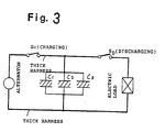
- Fig. 3 of the accompanying drawings schematically shows a circuit arrangement in which a plurality of (e.g., three) capacitors are employed to provide a large capacitance.
- the capacitors are charged by an alternator, and a starter is connected as an electric load to the capacitors.
- the capacitors, which are connected parallel to each other, and the alternator are coupled to each other by thick harnesses.
- a large current flows through the harnesses into the capacitors. The large current tends to shorten the service life of the alternator since the alternator is overloaded.
- Another object of the present invention is to provide a power supply device which will not overload a charging power supply such as an alternator that charges a plurality of capacitors of the power supply device.
- a power supply device comprising a charging power supply, a plurality of capacitors, chargeable by the charging power supply, for supplying stored electric energy to an electric load, and successive charging means for successively charging the capacitors with the charging power supply.
- Fig. 1 shows a power supply device for a motor vehicle, according to an embodiment of the present invention.
- the power supply device has a plurality of (three in Fig. 1) large-capacitance capacitors C1, C2, C3 connected parallel to each other, each of the capacitors C1, C2, C3 comprising an electric double layer capacitor.
- An alternator G which is driven by an engine includes a rectifying circuit and produces DC electric energy at its output terminal.
- the alternator G serves as a power supply for charging the capacitors C1, C2, C3 and also a battery B.
- a switch SC serves as a charging switch for the capacitors C1, C2, C3.
- a switch SD serves to supply electric energy stored in the capacitors C1, C2, C3 to an electric load L such as an engine starter on the motor vehicle, for thereby starting the engine on the motor vehicle.
- a relay circuit R1 has normally open contacts RSI, RSII, the contact RSII being connected to the positive terminal of the capacitor C1.
- a relay circuit R2 has a normally open contact RS2 connected to the positive terminal of the capacitor C2.
- a relay circuit R3 has a normally open contact RS3 connected to the positive terminal of the capacitor C3.
- the relay circuits R1, R2, R3 are connected such that when these relay circuits R1, R2, R3 are energized, circuits including their corresponding capacitors C1, C2, C3 are made or turned on.
- Unidirectional elements comprising diodes D1 through D5 are connected to the capacitors C1, C2, C3. More specifically, when the capacitors C1, C2, C3 are charged, the diodes D1, D2 are connected in series with the capacitors C1, C2, respectively. When the capacitors C1, C2, C3 are discharged, the diodes D3, D4, D5 are connected in series with tha capacitors C1, C2, C3, respectively.
- Zener diodes ZD1, ZD2 allow only a small current to pass therethrough when a reverse voltage applied thereto is lower than a predetermined value (breakdown voltage), but allows a sudden reverse current to pass therethrough when the reverse voltage reaches the predetermined value.
- the zener diode ZD1 has a cathode connected to the terminal of the contact RSII remote from the capacitor C1, and an anode connected to the coil of the relay circuit R2. When the capacitor C1 is charged, the contact RSII is closed.
- the voltage across the capacitor C1 rises up to the breakdown voltage of the zener diode ZD1, whereupon a current from the alternator G and the battery B flows through the diode D1 and the zener diode ZD1 into the coil of the relay circuit R2.
- the contact RS2 of the relay circuit R2 is now closed to start charging the capacitor C2 with the current which is supplied through the diode D2.
- the zener diode ZD2 has a cathode connected to the terminal of the contact RS2 remote from the capacitor C2, and an anode connected to the coil of the relay circuit R3. As is the case with the zener diode ZD1, the zener diode ZD2 detects a final stage of the process of charging the capacitor C2 and energizes the relay circuit R3 to charge the capacitor C3.
- the switch SC In order to charge the capacitors C1, C2, C3, the switch SC is closed.
- the coil of the relay circuit R1 is energized to close the contacts RSI, RSII thereof.
- the voltage of the alternator G and the battery B is applied through the diode D1 and the contact RSII to the capacitor C1, which now starts being charged.
- the process of charging the capacitor C1 approaches its final stage.
- the relay circuit R2 is energized with the current flowing through the diode D1 and the zener diode ZD1.
- the contact RS2 of the relay circuit R2 is closed, whereupon the capacitor C2 starts being charged.
- the process of charging the capacitor C2 also approaches its final stage.
- a sudden reverse current flowing through the zener diode D2 energizes the relay circuit R3, thereby charging the capacitor C3.
- the alternator G and the battery B supply a current, which is required to charge only one capacitor, successively to the capacitors C1, C2, C3. In this manner, the charging of the capacitors C1, C2, C3 is completed.
- Fig. 2 shows the relationship between a charting time and a charging current which is supplied to charge the capacitors C1, C2, C3.
- the solid-line curve shows the charging current supplied from the alternator G and the battery B in the power supply device according to the present invention.
- the dotted-line curve shows a charging current which is required to charge three parallel-connected capacitors in a conventional power supply device.
- the current supplied to charge the capacitors in the power supply device of the present invention is of a peak value which is about 1/3 of the peak value of the charging current flowing into the capacitors in the conventional power supply device.
- the switch SD is opened to stop the discharging of the electric energy from the capacitors C1, C2, C3.
- the capacitors C1, C2, C3 thus discharged can be charged again in the manner described above.
- the large-capacitance capacitors C1, C2, C3 are not simultaneously charged by the alternator G or the battery B, but are successively charged, one by one, by the zener diodes ZD1, ZD2 and the relay circuits R2, R3, which serve as a successivelysive charging means.
- the peak value of the charging current required to charge the capacitors C1, C2, C3 is much lower than that of the charging current supplied to charge the capacitors in the conventional power supply device. Therefore, the charging power supply and the capacitors may be connected by wires which have a much lower current capacity. Since the wires used have a small cross-sectional area, the harnesses can be wired with ease.
- the charging current supplied during an initial charging stage has a low peak value, the charging power supply or alternator is prevented from being overloaded, and the service life of the alternator is not unduly shortened.
Landscapes
- Engineering & Computer Science (AREA)
- Power Engineering (AREA)
- Mechanical Engineering (AREA)
- Chemical & Material Sciences (AREA)
- Business, Economics & Management (AREA)
- Emergency Management (AREA)
- Transportation (AREA)
- Combustion & Propulsion (AREA)
- General Engineering & Computer Science (AREA)
- Charge And Discharge Circuits For Batteries Or The Like (AREA)
- Direct Current Feeding And Distribution (AREA)
- Control Of Charge By Means Of Generators (AREA)
- Secondary Cells (AREA)
Applications Claiming Priority (2)
| Application Number | Priority Date | Filing Date | Title |
|---|---|---|---|
| JP195345/89 | 1989-07-27 | ||
| JP1195345A JPH0360330A (ja) | 1989-07-27 | 1989-07-27 | 電源装置 |
Publications (3)
| Publication Number | Publication Date |
|---|---|
| EP0410559A2 true EP0410559A2 (de) | 1991-01-30 |
| EP0410559A3 EP0410559A3 (en) | 1991-12-11 |
| EP0410559B1 EP0410559B1 (de) | 1994-11-30 |
Family
ID=16339626
Family Applications (1)
| Application Number | Title | Priority Date | Filing Date |
|---|---|---|---|
| EP90303454A Expired - Lifetime EP0410559B1 (de) | 1989-07-27 | 1990-03-30 | Stromversorgungseinrichtung |
Country Status (7)
| Country | Link |
|---|---|
| US (1) | US5119010A (de) |
| EP (1) | EP0410559B1 (de) |
| JP (1) | JPH0360330A (de) |
| KR (1) | KR0169478B1 (de) |
| CN (1) | CN1024614C (de) |
| CA (1) | CA2022066C (de) |
| DE (1) | DE69014463T2 (de) |
Cited By (13)
| Publication number | Priority date | Publication date | Assignee | Title |
|---|---|---|---|---|
| FR2668865A1 (fr) * | 1990-10-25 | 1992-05-07 | Magneti Marelli Spa | Systeme de demarrage de moteur a combustion interne. |
| EP0564149A3 (en) * | 1992-04-03 | 1994-08-24 | Jeol Ltd | Storage capacitor power supply |
| FR2706697A1 (fr) * | 1993-06-17 | 1994-12-23 | Guillot De Rode Francois | Alimentation originale d'un moteur électrique. |
| FR2751145A1 (fr) * | 1996-07-09 | 1998-01-16 | Renault | Dispositif de controle de la charge d'un supercondensateur et procede de commande d'un tel dispositif |
| US5977748A (en) * | 1992-04-03 | 1999-11-02 | Jeol Ltd. | Storage capacitor power supply and method of operating same |
| WO2002081255A1 (en) * | 2001-04-05 | 2002-10-17 | Electrovaya Inc. | Energy storage device for loads having variable power rates |
| WO2003099605A1 (de) * | 2002-05-24 | 2003-12-04 | Daimlerchrysler Ag | Antriebssystem für ein kraftfahrzeug mit einem verbrennungsmotor und einer elektrischen maschine |
| WO2005027345A1 (en) * | 2003-09-15 | 2005-03-24 | Electrovaya Inc. | Energy storage device for loads having variable power consumption |
| WO2009037043A3 (de) * | 2007-09-14 | 2009-05-28 | Bosch Gmbh Robert | Lade- und trennschaltung |
| US8097975B2 (en) | 2002-05-24 | 2012-01-17 | Daimler Ag | Drive system for a motor vehicle comprising an internal combustion engine and an electric motor |
| EP1775154A3 (de) * | 2001-04-05 | 2014-05-07 | Electrovaya Inc. | Energieträger für variierende Lasten |
| EP2009759A4 (de) * | 2006-04-14 | 2017-10-04 | Toyota Jidosha Kabushiki Kaisha | Energieversorgungsvorrichtung und verfahren zur steuerung einer energieversorgungsvorrichtung |
| CN110014963A (zh) * | 2017-12-14 | 2019-07-16 | 浙江万马新能源有限公司 | 充电枪掉电解锁供电电源电路及其控制方法 |
Families Citing this family (40)
| Publication number | Priority date | Publication date | Assignee | Title |
|---|---|---|---|---|
| GB9107507D0 (en) * | 1991-04-09 | 1991-05-22 | Yang Tai Her | A battery charging system |
| IT1251206B (it) * | 1991-09-18 | 1995-05-04 | Magneti Marelli Spa | Impianto elettrico di un autoveicolo, comprendente almeno un supercondensatore. |
| US5572108A (en) * | 1992-01-07 | 1996-11-05 | Windes; John A. | Power system using battery-charged capacitors |
| JP3226599B2 (ja) * | 1992-05-19 | 2001-11-05 | 東芝アイティー・コントロールシステム株式会社 | バッテリーカーの制御方法及び装置 |
| US6075331A (en) * | 1993-03-18 | 2000-06-13 | Imra America, Inc. | Systems and methods for managing energy of electric power supply systems |
| JPH06343225A (ja) * | 1993-05-28 | 1994-12-13 | Asahi Glass Co Ltd | 蓄電電源装置 |
| US5568035A (en) * | 1993-10-15 | 1996-10-22 | Sony/Tektronix Corporation | Variable-capacitance power supply apparatus |
| JPH0884434A (ja) * | 1994-09-08 | 1996-03-26 | Ueda:Kk | 電池装置及びこれを用いた間欠動作装置 |
| JPH08236806A (ja) * | 1995-02-27 | 1996-09-13 | Minolta Co Ltd | フォトインタラプタの取付構造 |
| US5905371A (en) * | 1995-06-23 | 1999-05-18 | D.C. Transformation, Inc. | Sequential discharge and its use for rectification |
| JPH0988778A (ja) * | 1995-07-17 | 1997-03-31 | Denso Corp | 始動発電装置 |
| US5932992A (en) * | 1996-02-16 | 1999-08-03 | The Pilot Ink Co., Ltd. | Method for energizing energization-operated toy element and energization-operated toy |
| JP3617183B2 (ja) * | 1996-05-08 | 2005-02-02 | トヨタ自動車株式会社 | 電気自動車の電源装置 |
| US5986907A (en) * | 1996-06-21 | 1999-11-16 | Limpaecher; Rudolf | Method and apparatus for rectification derectification and power flow control |
| US6016049A (en) * | 1998-06-24 | 2000-01-18 | Teleflex Incorporated | Capacitive supercharger for electric shift mechanism |
| DE19931972A1 (de) * | 1999-07-09 | 2001-01-11 | Wabco Gmbh & Co Ohg | Schaltungsanordnung zum Betreiben eines elektromagnetischen Stellglieds |
| JP3373459B2 (ja) * | 1999-09-07 | 2003-02-04 | 本田技研工業株式会社 | ハイブリッド自動車の制御装置 |
| JP3280642B2 (ja) * | 1999-09-08 | 2002-05-13 | 長野日本無線株式会社 | 蓄電モジュール |
| JP3526028B2 (ja) * | 2000-10-18 | 2004-05-10 | Necトーキン株式会社 | 電源回路、電源回路の制御方法、及びこの電源回路を用いた電子機器 |
| US6605921B2 (en) * | 2001-08-31 | 2003-08-12 | Denso Corporation | Electric power supply system for engine starters |
| JP3741630B2 (ja) * | 2001-09-18 | 2006-02-01 | Necトーキン株式会社 | 電源回路、該電源回路を備えた電子機器、及び電源回路の制御方法 |
| KR100616367B1 (ko) * | 2002-07-29 | 2006-08-28 | 김두현 | 엠보싱벽지 제조방법 |
| KR20040021707A (ko) * | 2002-08-29 | 2004-03-11 | (주)오크라 | 교류발전기의 전압 안정화장치 |
| KR20040038005A (ko) * | 2002-10-31 | 2004-05-08 | 에스케이텔레텍주식회사 | 배터리 충전전류를 발생하기 위한 이동통신 단말기 및그를 이용한 배터리 충전 방법 |
| US7277781B2 (en) * | 2004-05-14 | 2007-10-02 | General Motors Corporation | Method of undervoltage protection during engine cranking |
| US7663347B2 (en) * | 2006-04-20 | 2010-02-16 | Wu-Lie Shiu | Efficiency improving device for a gasoline engine |
| JP2008017593A (ja) * | 2006-07-05 | 2008-01-24 | Nissan Motor Co Ltd | 車両用電源システム |
| DE102006032881A1 (de) * | 2006-07-15 | 2008-01-17 | Daimler Ag | Batterielose Bordnetzversorgung im Kfz |
| JP5421954B2 (ja) * | 2011-05-18 | 2014-02-19 | 三菱電機株式会社 | 蓄電装置 |
| CN103114950B (zh) * | 2013-02-01 | 2015-08-26 | 莫嘉林 | 双启动电源系统 |
| CN203217281U (zh) * | 2013-02-05 | 2013-09-25 | 孙建朋 | 车辆电子调节器 |
| US10003293B2 (en) | 2013-03-15 | 2018-06-19 | Andrew John Bartlik | Portable motor drive system |
| JP5580914B1 (ja) * | 2013-03-22 | 2014-08-27 | トヨタ自動車株式会社 | 電源制御装置 |
| US9276511B2 (en) | 2014-02-04 | 2016-03-01 | Kohler Co. | Field current profile |
| JP6107763B2 (ja) * | 2014-08-05 | 2017-04-05 | 株式会社豊田自動織機 | 車両の電源装置 |
| JP6469424B2 (ja) * | 2014-11-28 | 2019-02-13 | 株式会社デンソーテン | 車両用電源装置 |
| JP6457840B2 (ja) * | 2015-03-02 | 2019-01-23 | マーレエレクトリックドライブズジャパン株式会社 | 内燃機関用制御装置及びそれを用いた制御方法 |
| WO2021061085A1 (en) | 2019-09-23 | 2021-04-01 | Seabourne Solutions, Llc | Power generator |
| FR3166767A1 (fr) * | 2024-09-26 | 2026-03-27 | Latelec | Réserve d’énergie capacitive à courant d’appel maîtrisé et équipement embarqué doté d’une telle réserve d’énergie capacitive |
| CN121308221A (zh) * | 2025-10-31 | 2026-01-09 | 厦门钧胜广源半导体有限公司 | 储能系统及方法、供电系统及方法 |
Family Cites Families (15)
| Publication number | Priority date | Publication date | Assignee | Title |
|---|---|---|---|---|
| US2979551A (en) * | 1959-03-02 | 1961-04-11 | Herschel G Pack | Thermoelectric generator |
| FR2032211A5 (de) * | 1969-02-21 | 1970-11-20 | Accumulateurs Fixes | |
| FR2082146A5 (de) * | 1970-03-04 | 1971-12-10 | Inst Francais Du Petrole | |
| US3693068A (en) * | 1970-07-08 | 1972-09-19 | John C Bogue | Electrical power supply comprising sequentially activated batteries |
| US4016474A (en) * | 1975-04-25 | 1977-04-05 | Ecc Corporation | Circuit for controlling the charging current supplied to a plurality of battery loads in accordance with a predetermined program |
| JPS55111078A (en) * | 1979-02-20 | 1980-08-27 | Ricoh Co Ltd | Direct current power supply |
| US4313078A (en) * | 1979-12-05 | 1982-01-26 | Rca Corporation | Battery charging system |
| JPS60152230A (ja) * | 1984-01-14 | 1985-08-10 | ロ−ム株式会社 | 充電回路 |
| JPS61189124A (ja) * | 1985-02-14 | 1986-08-22 | サンデン株式会社 | 自転車用電源装置 |
| JPS61280711A (ja) * | 1985-03-29 | 1986-12-11 | 富士通株式会社 | 電源開閉回路 |
| SU1265391A1 (ru) * | 1985-04-17 | 1986-10-23 | Московский автомеханический институт | Система электростартерного пуска двигател внутреннего сгорани |
| JPS622821A (ja) * | 1985-06-27 | 1987-01-08 | 松下電器産業株式会社 | コンデンサ充電回路 |
| EP0222381B1 (de) * | 1985-11-15 | 1992-07-15 | Sanyo Electric Co., Ltd. | Ladevorrichtung |
| SU1326769A1 (ru) * | 1986-03-31 | 1987-07-30 | Предприятие П/Я А-1877 | Система электростартерного пуска дл двигател внутреннего сгорани |
| SU1456632A2 (ru) * | 1987-01-12 | 1989-02-07 | Московский Институт Инженеров Железнодорожного Транспорта | Система электростартерного пуска двигател внутреннего сгорани |
-
1989
- 1989-07-27 JP JP1195345A patent/JPH0360330A/ja active Pending
-
1990
- 1990-03-30 EP EP90303454A patent/EP0410559B1/de not_active Expired - Lifetime
- 1990-03-30 DE DE69014463T patent/DE69014463T2/de not_active Expired - Fee Related
- 1990-03-30 US US07/501,748 patent/US5119010A/en not_active Expired - Fee Related
- 1990-07-26 CA CA002022066A patent/CA2022066C/en not_active Expired - Fee Related
- 1990-07-27 KR KR1019900011485A patent/KR0169478B1/ko not_active Expired - Fee Related
- 1990-07-27 CN CN90106967A patent/CN1024614C/zh not_active Expired - Fee Related
Cited By (16)
| Publication number | Priority date | Publication date | Assignee | Title |
|---|---|---|---|---|
| FR2668865A1 (fr) * | 1990-10-25 | 1992-05-07 | Magneti Marelli Spa | Systeme de demarrage de moteur a combustion interne. |
| EP0564149A3 (en) * | 1992-04-03 | 1994-08-24 | Jeol Ltd | Storage capacitor power supply |
| US5977748A (en) * | 1992-04-03 | 1999-11-02 | Jeol Ltd. | Storage capacitor power supply and method of operating same |
| US6424156B1 (en) | 1992-04-03 | 2002-07-23 | Jeol Ltd. | Storage capacitor power supply |
| FR2706697A1 (fr) * | 1993-06-17 | 1994-12-23 | Guillot De Rode Francois | Alimentation originale d'un moteur électrique. |
| FR2751145A1 (fr) * | 1996-07-09 | 1998-01-16 | Renault | Dispositif de controle de la charge d'un supercondensateur et procede de commande d'un tel dispositif |
| US7570012B2 (en) | 2001-04-05 | 2009-08-04 | Electrovaya Inc. | Energy storage device for loads having variable power rates |
| WO2002081255A1 (en) * | 2001-04-05 | 2002-10-17 | Electrovaya Inc. | Energy storage device for loads having variable power rates |
| EP1775154A3 (de) * | 2001-04-05 | 2014-05-07 | Electrovaya Inc. | Energieträger für variierende Lasten |
| CN1304217C (zh) * | 2001-04-05 | 2007-03-14 | 伊莱克特罗维亚公司 | 用于具有可变功率的负载的能量储存装置 |
| US8097975B2 (en) | 2002-05-24 | 2012-01-17 | Daimler Ag | Drive system for a motor vehicle comprising an internal combustion engine and an electric motor |
| WO2003099605A1 (de) * | 2002-05-24 | 2003-12-04 | Daimlerchrysler Ag | Antriebssystem für ein kraftfahrzeug mit einem verbrennungsmotor und einer elektrischen maschine |
| WO2005027345A1 (en) * | 2003-09-15 | 2005-03-24 | Electrovaya Inc. | Energy storage device for loads having variable power consumption |
| EP2009759A4 (de) * | 2006-04-14 | 2017-10-04 | Toyota Jidosha Kabushiki Kaisha | Energieversorgungsvorrichtung und verfahren zur steuerung einer energieversorgungsvorrichtung |
| WO2009037043A3 (de) * | 2007-09-14 | 2009-05-28 | Bosch Gmbh Robert | Lade- und trennschaltung |
| CN110014963A (zh) * | 2017-12-14 | 2019-07-16 | 浙江万马新能源有限公司 | 充电枪掉电解锁供电电源电路及其控制方法 |
Also Published As
| Publication number | Publication date |
|---|---|
| DE69014463T2 (de) | 1995-05-24 |
| JPH0360330A (ja) | 1991-03-15 |
| CN1024614C (zh) | 1994-05-18 |
| DE69014463D1 (de) | 1995-01-12 |
| CN1049938A (zh) | 1991-03-13 |
| US5119010A (en) | 1992-06-02 |
| CA2022066C (en) | 1995-08-01 |
| CA2022066A1 (en) | 1991-01-28 |
| KR0169478B1 (ko) | 1999-04-15 |
| EP0410559A3 (en) | 1991-12-11 |
| EP0410559B1 (de) | 1994-11-30 |
| KR910003890A (ko) | 1991-02-28 |
Similar Documents
| Publication | Publication Date | Title |
|---|---|---|
| EP0410559B1 (de) | Stromversorgungseinrichtung | |
| CA2012390C (en) | Engine starter system | |
| EP0403051B1 (de) | Verbrennungsmotor-Anlassersystem | |
| US6057666A (en) | Method and circuit for controlling charging in a dual battery electrical system | |
| US7800346B2 (en) | Device and method for equalizing charges of series-connected energy stores | |
| US9816475B1 (en) | System and method for maximizing short-term energy storage in a supercapacitor array for engine start applications | |
| EP3079221B1 (de) | Notfall-startvorrichtung und notfall-start verfahren | |
| US6325035B1 (en) | Method and apparatus for starting an engine using capacitor supplied voltage | |
| CN101926083B (zh) | Dc-dc转换器 | |
| EP0412631A2 (de) | Stromversorgungseinrichtung für Kraftfahrzeug | |
| AU2016273816B2 (en) | Apparatus for starting an electrically cranked engine | |
| KR102125057B1 (ko) | 차량용 점프스타트 장치 | |
| JP7458326B2 (ja) | 電池監視制御回路 | |
| JP2001298873A (ja) | 車両用電源装置 | |
| CA2799488A1 (en) | System and method for electrical energy switching and control in a vehicle | |
| EP1025632B1 (de) | Verfahren und einrichtung zur ladesteuerung in einem elektrischen system mit zwei batterien | |
| CN110266100A (zh) | 电源切换电路和电源切换方法 | |
| KR101380756B1 (ko) | 고전력 부하 장치를 포함하는 마이크로 하이브리드 차량용 배터리 시스템 | |
| US7477040B2 (en) | Circuit for a motor vehicle electrical distribution system and an associated operating method | |
| JPH02175351A (ja) | 車両用補助電源 | |
| RU2027063C1 (ru) | Система электростартерного пуска двигателя внутреннего сгорания | |
| PL176138B1 (pl) | Układ przełączający do sterowania rodzajem pracy chemoelektrycznej bateriiakumulatoróww instalacji prądu dtałeaoz obwodom silnonrądowow |
Legal Events
| Date | Code | Title | Description |
|---|---|---|---|
| PUAI | Public reference made under article 153(3) epc to a published international application that has entered the european phase |
Free format text: ORIGINAL CODE: 0009012 |
|
| AK | Designated contracting states |
Kind code of ref document: A2 Designated state(s): DE FR GB IT |
|
| PUAL | Search report despatched |
Free format text: ORIGINAL CODE: 0009013 |
|
| AK | Designated contracting states |
Kind code of ref document: A3 Designated state(s): DE FR GB IT |
|
| 17P | Request for examination filed |
Effective date: 19920528 |
|
| 17Q | First examination report despatched |
Effective date: 19931118 |
|
| GRAA | (expected) grant |
Free format text: ORIGINAL CODE: 0009210 |
|
| AK | Designated contracting states |
Kind code of ref document: B1 Designated state(s): DE FR GB IT |
|
| REF | Corresponds to: |
Ref document number: 69014463 Country of ref document: DE Date of ref document: 19950112 |
|
| ITF | It: translation for a ep patent filed | ||
| ET | Fr: translation filed | ||
| PLBE | No opposition filed within time limit |
Free format text: ORIGINAL CODE: 0009261 |
|
| STAA | Information on the status of an ep patent application or granted ep patent |
Free format text: STATUS: NO OPPOSITION FILED WITHIN TIME LIMIT |
|
| 26N | No opposition filed | ||
| PGFP | Annual fee paid to national office [announced via postgrant information from national office to epo] |
Ref country code: FR Payment date: 19980310 Year of fee payment: 9 |
|
| PGFP | Annual fee paid to national office [announced via postgrant information from national office to epo] |
Ref country code: GB Payment date: 19980323 Year of fee payment: 9 |
|
| PGFP | Annual fee paid to national office [announced via postgrant information from national office to epo] |
Ref country code: DE Payment date: 19980403 Year of fee payment: 9 |
|
| PG25 | Lapsed in a contracting state [announced via postgrant information from national office to epo] |
Ref country code: GB Free format text: LAPSE BECAUSE OF NON-PAYMENT OF DUE FEES Effective date: 19990330 |
|
| GBPC | Gb: european patent ceased through non-payment of renewal fee |
Effective date: 19990330 |
|
| PG25 | Lapsed in a contracting state [announced via postgrant information from national office to epo] |
Ref country code: FR Free format text: LAPSE BECAUSE OF NON-PAYMENT OF DUE FEES Effective date: 19991130 |
|
| REG | Reference to a national code |
Ref country code: FR Ref legal event code: ST |
|
| PG25 | Lapsed in a contracting state [announced via postgrant information from national office to epo] |
Ref country code: DE Free format text: LAPSE BECAUSE OF NON-PAYMENT OF DUE FEES Effective date: 20000101 |
|
| PG25 | Lapsed in a contracting state [announced via postgrant information from national office to epo] |
Ref country code: IT Free format text: LAPSE BECAUSE OF NON-PAYMENT OF DUE FEES;WARNING: LAPSES OF ITALIAN PATENTS WITH EFFECTIVE DATE BEFORE 2007 MAY HAVE OCCURRED AT ANY TIME BEFORE 2007. THE CORRECT EFFECTIVE DATE MAY BE DIFFERENT FROM THE ONE RECORDED. Effective date: 20050330 |