EP0410610A2 - Kontinuierliche Überwachung von Konzentrationen durch zirkularen Dichroismus - Google Patents
Kontinuierliche Überwachung von Konzentrationen durch zirkularen Dichroismus Download PDFInfo
- Publication number
- EP0410610A2 EP0410610A2 EP90307644A EP90307644A EP0410610A2 EP 0410610 A2 EP0410610 A2 EP 0410610A2 EP 90307644 A EP90307644 A EP 90307644A EP 90307644 A EP90307644 A EP 90307644A EP 0410610 A2 EP0410610 A2 EP 0410610A2
- Authority
- EP
- European Patent Office
- Prior art keywords
- flowing solution
- flow cell
- concentration
- subject compound
- electromagnetic radiation
- Prior art date
- Legal status (The legal status is an assumption and is not a legal conclusion. Google has not performed a legal analysis and makes no representation as to the accuracy of the status listed.)
- Withdrawn
Links
Images
Classifications
-
- G—PHYSICS
- G01—MEASURING; TESTING
- G01N—INVESTIGATING OR ANALYSING MATERIALS BY DETERMINING THEIR CHEMICAL OR PHYSICAL PROPERTIES
- G01N23/00—Investigating or analysing materials by the use of wave or particle radiation, e.g. X-rays or neutrons, not covered by groups G01N3/00 – G01N17/00, G01N21/00 or G01N22/00
-
- G—PHYSICS
- G01—MEASURING; TESTING
- G01N—INVESTIGATING OR ANALYSING MATERIALS BY DETERMINING THEIR CHEMICAL OR PHYSICAL PROPERTIES
- G01N21/00—Investigating or analysing materials by the use of optical means, i.e. using sub-millimetre waves, infrared, visible or ultraviolet light
- G01N21/17—Systems in which incident light is modified in accordance with the properties of the material investigated
- G01N21/19—Dichroism
Definitions
- This invention relates to an apparatus and method for continuously monitoring the concentration of a compound which exhibits circular dichroism actively, and is contained in a flowing solution, in particular, a solution also containing a plurality of other compounds in solution.
- the concentration of a subject compound which is present in a flowing solution stream containing a plurality of compounds In industrial processes, it is frequently desired to monitor the concentration of a subject compound which is present in a flowing solution stream containing a plurality of compounds. Further, it is frequently desired that the concentration of the subject compound will be monitored continuously so that the concentration of that compound in the flowing solution stream that is passing the monitor will always be known.
- the apparatus and method selected for monitoring the concentration of the subject com depends in part on the chemical or physical characteristics of that compound and in part on the nature and characteristics of the industrial process of which the flowing solution stream is a part.
- the concentration of that compound might be determined by chemical methods such as high pressure liquid chromatography, gas chromatography, spectrophotometry, or, if the subject compound exhibits circular dichroism activity, by measurement using circular dichroism spectropolarimetry.
- Compounds which exhibit circular dichroism activity are those which contain a chiral centre in the molecule and which absorb ultraviolet or other electromagnetic radiation. This includes many molecules which are active in biological processes.
- a significant problem is that the isolation of the small volume of sample and the execution of the circular dichroism analysis are time consuming and require a significant amount of handling of the sample. Use of more than several minutes to make the concentration determination can negate the effectiveness of the method as a process monitor. This is because the point in the flowing solution stream from which the sample was taken will be too far downstream by the time the concentration of the subject compound in the sample is known. Further, where the flowing solution stream is maintained under extreme conditions of temperature or pressure, isolating a sample is made prohibitively difficult and altering the conditions of the sample to allow for handling can alter or destroy the integrity of the compounds in the sample. Thus, as presently performed, circular dichroism spectropolarimetry apparatus and methods may be prohibited for monitoring the concentration of compounds in some flowing sample streams.
- an apparatus for continuously monitoring the concentration of a subject compound in a flowing solution comprising: generating means for generating a beam of alternately left circularly polarized and right circularly polarized monochromatic electromagnetic radiation directed along a path; a flow cell positioned down said path from the generating means and having a first straight channel for passage of the flowing solution therethrough and a second channel for passage of the beam of electromagnetic radiation therethrough, the first and second channels intersecting at a point; first and second transparent plates comprised of a material which has no adverse dichroic effects on the beam of electromagnetic radiation, the plates being positioned in the flow cell to isolate the first channel from the second channel and so that the beam of electromagnetic radiation first traverses the first plate, then the flowing solution, and then the second transparent plate before exiting the flow cell; means for detecting the intensity of said beam of electromagnetic radiation after passage through the flowing solution in said flow cell and converting the detected intensity into an electrical signal comprising
- the invention also provides a method for continuously measuring the concentration of a subject compound in a flowing solution which compounds exhibits circular dichroism activity, comprising: providing the flowing solution which includes the subject compound; directing the flowing solution through a flow cell; generating a beam of electromagnetic radiation which is alternately left circularly polarized and right circularly polarized and which is directed along a path; passing the beam of electromagnetic radiation through said flowing solution in said flow cell; detecting the intensity of the beam of electromagnetic radiation after passage through the flowing solution in said flow cell and converting the intensity into an electronic signal arising a direct current component and an alternating current component, the alternating current component representing the difference of absorption of the left circularly polarized beam and the right circularly polarized beam; and determining the concentration of the subject compound in the flowing solution from the alternating current component and the direct current component.
- the invention has the advantage that it is capable of using circular dichroism spectropolarimetry to continuously monitor the concentration of a subject compound which exhibits circular dichroism activity in flowing solution streams without having to remove a sample or the solution from the flowing stream. Moreover, the method and an apparatus is capable of continuously monitoring the concentration of a subject compound in a flowing solution stream where the solution stream is maintained under extreme conditions of temperature and pressure.
- the present invention provides for an apparatus and method for continuously monitoring the concentration of a subject compound which exhibits circular dichroism activity in a flowing solution which contains a plurality of compounds.
- a preferred embodiment of the invention includes a generating means for generating a beam of alternately left circularly polarized and right circularly polarized monochromatic electromagnetic radiation.
- This beam of electromagnetic radiation is directed through a flow cell.
- the flow cell has a first and a second separate straight channel therethrough, which intersect at a single point along their paths.
- the flowing solution passes through the first channel and the beam of electromagnetic radiation passes through the second channel such that the beam of electromagnetic radiation must first traverse a first transparent plate, then the flowing solution, and then a second transparent plate before exiting the flow cell.
- the first and second transparent plates are located to isolate the first channel from the second channel and define the distance the beam of electromagnetic radiation must travel through the flowing solution.
- the first and second transparent plates must be comprised of a material which has no adverse dichroic effects on the beam of electromagnetic radiation.
- the intensity of the beam of electromagnetic radiation is detected by a means for detecting which converts the intensity measure into an electronic signal containing a direct current component and an alternating current component.
- the concentration of the subject compound is then found by a means for determining which measures the ratio of the direct current component to the alternating current component.
- the concentration measure is then recorded by a means for recording.
- the apparatus includes means for recording and/or displaying the concentration of the subject compound.
- the concentration determining means is determined from the ratio of the D.C. component to the A.C. component.
- the flow cell can accomodate a flowing solution at a pressure greater than atmospheric.
- the flow cell can be heated to correspond to the temperature of the flowing solution.
- the distance between the first and second transparent plate is 2-3 millimeters or as is appropriate for the flowing solution selected.
- the method of the present invention includes providing a flowing solution including a subject compound that exhibits circular dichroism activity and directing the flowing solution through a flow cell, generating a beam of alternately left and right circularly polarized electromagnetic radiation, passing the beam of electromagnetic radiation through the flow cell and the flowing solution, detecting the intensity of the beam of electromagnetic radiation after passage through the flowing solution and converting the intensity measure into an electronic signal comprising a direct current component and an alternating current component, the alternating current component representing the difference of absorption of the left circularly polarized beam and the right circularly polarized beam, and determining the concentration of the subject compound in the flowing solution by measuring the ratio of the alternating current component to the direct current component.
- the flowing solution is provided at a pressure greater than atmospheric.
- the flowing solution provided comprises a super critical fluid solution.
- the flowing solution provided comprises a super critical fluid carbon dioxide solution.
- the subject compound is nicotine and the flowing solution provided comprises extracts from tobacco in super critical fluid carbon dioxide.
- the wavelength of the beam is chosen to correspond to the maximum circular dichroic absorbance of the subject compound.
- this radiation is in the ultraviolet spectrum.
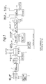
- electromagnetic radiation is generated by ozone-free short gap arc lamp 1, which is commercially avaliable from Optical Radiation Corp., 1300 Optical Drive, Azusa, California 91702, under model number USA-150-7.
- Arc lamp 1 is powered by arc lamp power supply 2, and resides in arc lamp housing 3.
- Electromagnetic radiation travels from arc lamp 1, through double convex lens 4, which directs the electromagnetic radiation at monochromator 5.
- Monochromator 5 is commercially available from Instruments, S.A., Inc., 6 Olson Avenue, Edison, New Jersey 08820, under model number R4315.
- Monochromator 5 is capable outputting electromagnetic radiation of a single wavelength over a wide range of wavelengths in the ultraviolet spectrum. This invention is intended to cover the use of this circular dichroism spectropolarimeter and method for its use over the entire wavelength range of monochromator 5.
- the wavelength selected should correspond with the wavelength of maximum circular dichroism absorption of a subject compound whose concentration is sought to be monitored.
- monochromator 5 is adjusted to output electromagnetic radiation of 264 nm, the wavelength found to give the maximum circular dichroism absorption for nicotine in a supercritical fluid carbon dioxide solution.
- Electromagnetic radiation outputted from monochromator 5 is directed at double convex lens 6, which focuses the radiation on polarizer 7.
- Polarizor 7 linearly polarizes the monochromatic electromatic radiation and allows it to travel into photoelastic modulator 8.
- Photoelastic modulator 8 which is commercially available from Hinds International, Inc., P.O. Box 929, Hillsboro, Oregon 97123-0929, under model number PEM-80, transforms the monochromatic electromagnetic radiation from being linearly polarized to being alternately left circularly polarized and right circularly polarized.
- Photoelastic modulator 8 effects this transformation by applying pulses of electric current at a given frequency to a crystaline quartz piezoelectric transducer (not shown) which is within the photoelastic modulator and through which the electromagnetic radiation travels.
- Application of this current phase-shifts the electromagnetic radiation, resulting in circularly polarized monochromatic radiation which alternates between left rotation and right rotation at a frequency equal to the frequency of the pulses of electric current applied to the piezoelectric transducer.
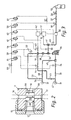
- Flow cell 9 which is commercially available from Harrick Scientific, Ossining, New York 10562, model no. HPLC-13, is depicted in FIG. 2.
- Flow cell 9 is comprised of two opposing transparent quartz plates 10 and 13, which are adjustably mounted in housing 11 so that the circularly polarized electromagnetic radiation entering flow cell 9 through opening 12, passes through quartz plate 13, then travels through the flowing sample solution, then passes through quartz plate 10, and exits the flow cell through exit opening 14.
- Housing 11 is constructed in such a way that the flow cell 9 is capable of withstanding flowing sample solution pressures of greater than 3500 psi.
- Flow cell 9 is capable of being heated to the temperature of the following solution.
- the flowing solution is held at a pressure of 3500 psi and a temperature of 140 F.
- the distance between quartz plate 13 and quartz plate 10 defines a path length and is adjustable.
- the path length is fixed by interposition of stainless steel spacer and by movement of collar 15 which secures quartz plate 13. Selection of the path length is important for accurate concentration measure.
- the path length must be long enough to obtain a measurable absorption of the circularly polarized radiation but not so long that background absorption will distort the measurement. It has been found that the best results are obtained with a pathlength range of 2-3mm. In a preferred embodiment of the invention, the pathlength is 3 mm.
- Housing 11 is constructed to allow passage of the flowing sample solution.
- the solution is allowed to travel between opening 16 and opening 17, passing through housing 11, then between quartz plates 13 and 10 and through the beam of electromagnetic radiation, then through housing 11 before exciting.
- Quartz plates 13 and 10 are each sealed to prevent leakage of the flowing sample solution by O-ring seals 65 and 66, respectively.
- the subject compound is nicotine in a flowing sample solution comprising extracts from tobacco and super critical fluid carbon dioxide it is critical that O-ring seals 65 and 66 be made of an ethylene/propylene copolymer which is commercially available and may be obtained from Parker Seals, O-ring Division, 2360 Palumbo Drive, Lexington, Kentucky 40509, under model number E0962-90 to maintain the seal.
- the flowing sample solution can be monitored at either of two points along the path of a sample stream, extractor port 31 or absorber port 32.
- the flowing sample solution enters that port and travels through blocking valve 33, which is manually controlled.
- the sample solution then travels through air-actuated valve 34, which is controlled by three-way valve 35. From air-actuated valve 34, the sample solution travels into pump 36.
- Flow restrictor 38 is important to the operation of the sample loop because it allows regulation of the pressure added to the sample solution in the sampling loop. It is desirable that this pressure change be minimal without effecting flow through the sample loop.
- sample solution After passing through flow cell 9, the sample solution travels through opening 17 and past flow meter 42 which measures the volume of the sample solution passing it per unit time.
- the sample solution then passes through air-activated valves 43 and 44 which are controlled by 3-way valves 46 and 35, respectively. After traveling through blocking valve 45, the sample solution is returned to the flowing sample stream through exit passage 47 which surrounds extractor port 31.
- the sample solution enters the sample loop at that port and passes through blocking valve 48 before passing through air-actuated valve 49, which is controlled by 3-way valve 50.
- the sample solution then travels into pump 36. From pump 36, the sample solution from absorber port 32 follows the same route as sample solution from extractor port 31 until it reaches intersection 51.
- the sample solution from absorber port 32 is directed through air-actuated valve 52, which is controlled by 3-way valve 50. From air-actuated valve 52 the flowing sample passes through blocking valve 53 and back into the flowing sample stream through exit passage 54 which surrounds absorber port 32.
- the sample solution is drawn from only one of the sampling ports by concerted action of 3-way valves 35, 40, 46 and 50.
- 3-way valves 35, 40 and 46 open air-actuated valves 34, 39, 43 and 44 while 3-way valve 50 keeps air-actuated valves 49 and 52 closed.
- 3-way valves 50, 40 and 46 open air-actuated valves 49, 39, 43 and 52 while 3-way valve 35 keeps air-actuated valves 34 and 44 closed.
- Flow cell 9 and flow meter 42 can be flushed of impurities precipitated from the sample solution with clean carbon dioxide.
- Carbon dioxide from reservoir 55 passes through manual shut-off valve 56, blocking valve 57 and air-actuated valve 58, which is controlled by 3-way valve 59, and into booster pump 60.
- Booster pump 60 propels the carbon dioxide toward opening 16 by the action of air from 3-way valve 61.
- the carbon dioxide then travels through air-actuated valve 62 which is controlled by 3-way valve 63, through opening 16, flow cell 9, opening 17, and flow meter 42.
- the carbon dioxide and impurities could travel from air-actuated valve 43 through air-actuated valve 52 and blocking valve 53 before exiting into the flowing solution through exit passage 54.
- 3-way valves 35, 50, 46, 40, 63, 59 and 61 control the respective air-activated valves by regulating the flow of air to the air-regulated valves.
- Manual shut-off valve 64 controls the flow of air to the 3-way valves.
- the flowing sample stream is included in an industrial process as described in pending United States Patent Applications Serial Nos. 122,760 and 122,761.
- the flowing solution stream and the sample solution which travels through flow cell 9 contains super critical carbon dioxide at a pressure of 3000-3500 psi. and a temperature of about 140 deg. F. and also includes nicotine and other compounds which are extracted from tobacco.
- Photomultiplier 22 transforms the circularly polarized electromagnetic radiation into a electronic signal with a direct current component and an alternating current component.
- the direct current component represents radiation which as been partially absorbed by compounds in the flowing solution which do not exhibit circular dichroism activity.
- the alternating current component represents the difference of absorption of the left circular polarized beam and the right circularly polarized beam by the subject compound which exhibits circular dichroism activity.
- the direct current component travels to low voltage pre-amp 23 where the signal is amplified.
- the amplified direct current component then travels to ratio circuit 24.
- the alternating current component travels through low voltage pre-amp 23 to lock-in amplifier 25, which amplifies the alternating current signal.
- Lock-in amplifier 25 is electronically connected to modulator 8 by controller 26. Controller 26 transmits an electronic signal to lock-in amplifier 25 representative of the frequency of the electric current pulses applied to the piezoelectric transducer of modulator 8. This signal allows lock-in amplifier 25 to more strongly amplify the alternating current signal in the frequency range corresponding to the frequency of the current pulses being applied to the piezoelectric transducer of modulator 8.
- Ratio circuit 24 electronically calculates the ratio of the alternating current signal to the direct current signal.
- the alternating current signal, direct current signal and an electronic signal representing the ratio of alternating current to direct current are then transmitted by RS-232 digital channel 27 to digital computer 28.
- Digital computer 28 is programmed to be capable of outputting the concentration of the subject compound or data corresponding to the direct current signal or the alternating current signal. This output can be by analog output 29 or by digital output 30.
Landscapes
- Physics & Mathematics (AREA)
- Health & Medical Sciences (AREA)
- Life Sciences & Earth Sciences (AREA)
- Chemical & Material Sciences (AREA)
- Analytical Chemistry (AREA)
- Biochemistry (AREA)
- General Health & Medical Sciences (AREA)
- General Physics & Mathematics (AREA)
- Immunology (AREA)
- Pathology (AREA)
- Investigating Or Analysing Materials By Optical Means (AREA)
- Extraction Or Liquid Replacement (AREA)
- Measurement Of The Respiration, Hearing Ability, Form, And Blood Characteristics Of Living Organisms (AREA)
Applications Claiming Priority (2)
| Application Number | Priority Date | Filing Date | Title |
|---|---|---|---|
| US383717 | 1989-07-24 | ||
| US07/383,717 US5036204A (en) | 1989-07-24 | 1989-07-24 | Continuous concentration monitoring by circular dichroism |
Publications (2)
| Publication Number | Publication Date |
|---|---|
| EP0410610A2 true EP0410610A2 (de) | 1991-01-30 |
| EP0410610A3 EP0410610A3 (en) | 1991-05-02 |
Family
ID=23514400
Family Applications (1)
| Application Number | Title | Priority Date | Filing Date |
|---|---|---|---|
| EP19900307644 Withdrawn EP0410610A3 (en) | 1989-07-24 | 1990-07-12 | Continuous concentration monitoring by circular dichroism |
Country Status (5)
| Country | Link |
|---|---|
| US (1) | US5036204A (de) |
| EP (1) | EP0410610A3 (de) |
| JP (1) | JPH03130645A (de) |
| KR (1) | KR910003372A (de) |
| DD (1) | DD296758A5 (de) |
Cited By (4)
| Publication number | Priority date | Publication date | Assignee | Title |
|---|---|---|---|---|
| US5777726A (en) * | 1992-05-12 | 1998-07-07 | Raytheon Company | Spectrophotometric supercritical fluid contamination monitor |
| EP0916945A1 (de) * | 1997-11-14 | 1999-05-19 | Jasco Corporation | Detektor zum Nachweis von zirkularem Dichroismus für HPLC |
| EP0881485A4 (de) * | 1996-11-15 | 2001-09-12 | Inst Molekulyarnoi Biolog Im V | Verfahren zur bestimmung einer biologisch aktiven substanz in einer zu analysierenden flüssigkeit und dieses realisierende vorrichtung |
| US20100053619A1 (en) * | 2006-11-17 | 2010-03-04 | Richard Timothy Dafforn | Molecular detection system |
Families Citing this family (13)
| Publication number | Priority date | Publication date | Assignee | Title |
|---|---|---|---|---|
| JP2669732B2 (ja) * | 1990-07-27 | 1997-10-29 | 昭和電工株式会社 | 旋光度検出方法、その検出装置および旋光度検出用セル |
| JPH0772700B2 (ja) * | 1991-07-05 | 1995-08-02 | 日本分光株式会社 | 位相差制御装置及び方法 |
| US5412467A (en) * | 1993-03-24 | 1995-05-02 | Praxair Technology, Inc. | Gas emission spectrometer and method |
| CZ286103B6 (cs) * | 1993-11-26 | 2000-01-12 | Rokos A Spol., S.R.O. | Způsob měření spektropolarimetrických vlastností opticky aktivních látek a dichrograf k provedení tohoto způsobu |
| US5457536A (en) * | 1994-04-04 | 1995-10-10 | California Institute Of Technology | Polarization modulation laser scanning microscopy |
| WO1997018470A1 (en) * | 1995-11-16 | 1997-05-22 | Matsushita Electric Industrial Co., Ltd. | Method and apparatus for urinalysis, method of measuring optical rotation and polarimeter |
| JP3308173B2 (ja) * | 1996-11-07 | 2002-07-29 | 松下電器産業株式会社 | 尿検査方法およびそれに用いる尿検査装置 |
| US6687012B2 (en) | 2001-10-30 | 2004-02-03 | Fordham University | Apparatus and method for measuring optical activity |
| WO2005116636A1 (en) * | 2004-05-25 | 2005-12-08 | Renner Herrmann S.A. | An apparatus and method for measuring the spectral properties of a fluid |
| JP4899169B2 (ja) * | 2006-02-02 | 2012-03-21 | 国立大学法人 奈良先端科学技術大学院大学 | 円二色性蛍光顕微鏡 |
| JP2008224342A (ja) * | 2007-03-12 | 2008-09-25 | Rion Co Ltd | フローセル、フローセルの製造方法及び粒子測定装置 |
| JP2011247756A (ja) * | 2010-05-27 | 2011-12-08 | Jasco Corp | Atr法を用いた円二色分散測定方法及び円二色分散計 |
| WO2021086746A1 (en) * | 2019-10-28 | 2021-05-06 | North Carolina State University | Reduced pathlength flow cell for inline sample characterization in modular fluoropolymer tubing microfluidics |
Family Cites Families (22)
| Publication number | Priority date | Publication date | Assignee | Title |
|---|---|---|---|---|
| US2976764A (en) * | 1958-12-04 | 1961-03-28 | American Optical Corp | Polarimeters |
| BE605571A (de) * | 1960-06-29 | |||
| US3283645A (en) * | 1962-04-26 | 1966-11-08 | Wada Akiyoshi | Laminar flow dichroism polarimeter |
| US3345907A (en) * | 1963-06-17 | 1967-10-10 | Wada Akiyoshi | Dichroism spectroscopes |
| DE1226328B (de) * | 1965-03-13 | 1966-10-06 | Bodenseewerk Perkin Elmer Co | Vorrichtung zur gleichzeitigen Messung von optischer Drehung und Zirkular-Dichroismus |
| GB1142501A (en) * | 1965-04-21 | 1969-02-12 | Pye Ltd | Improvements in or relating to the measurement of circular dichroism |
| FR1456702A (fr) * | 1965-08-13 | 1966-07-08 | Roussel Uclaf | Procédé et appareil pour l'étude du dichroïsme circulaire magnétique des substances absorbantes |
| FR1506332A (fr) * | 1966-05-26 | 1967-12-22 | Centre Nat Rech Scient | Appareil de mesure et d'entregistrement du dichroïsme circulaire |
| US3637311A (en) * | 1967-10-30 | 1972-01-25 | Durrum Instr | Optical dichroism measuring apparatus and method |
| US3586443A (en) * | 1968-04-22 | 1971-06-22 | Cary Instruments | Circular dichroism measurement system |
| US3612688A (en) * | 1968-11-13 | 1971-10-12 | American Standard Inc | Suspended organic particles monitor using circularly polarized light |
| US3632216A (en) * | 1969-05-28 | 1972-01-04 | Cary Instruments | Circular-dichroism measurement system characterized by noise cancellation |
| SU374971A1 (de) * | 1969-08-01 | 1973-11-05 | ||
| US3602597A (en) * | 1969-09-17 | 1971-08-31 | Durrum Instr | Differential circular dichroism measuring apparatus |
| US3741660A (en) * | 1971-10-27 | 1973-06-26 | Cary Instruments | Conversion of circular dichroism spectropolarimeter to linear dichroism measurement mode |
| SU485367A1 (ru) * | 1972-10-27 | 1975-09-25 | Всесоюзный Научно-Исследовательский И Экспериментально-Конструкторский Институт Продовольственного Машиностроения | Автоматический прибор дл регистрации спектров циркул рного дихроизма |
| FR2362388A1 (fr) * | 1976-08-18 | 1978-03-17 | Anvar | Dispositif optique pour des mesures de dichroisme |
| US4523847A (en) * | 1983-07-07 | 1985-06-18 | International Business Machines Corporation | Frequency modulation-polarization spectroscopy method and device for detecting spectral features |
| CA1242336A (en) * | 1984-08-16 | 1988-09-27 | Winnipeg Rh Institute Inc. (The) | Sight tube for monitoring of fluids |
| US4588893A (en) * | 1985-02-25 | 1986-05-13 | Nicolet Instrument Corporation | Light-pipe flow cell for supercritical fluid chromatography |
| JPS63115031A (ja) * | 1986-10-31 | 1988-05-19 | Japan Spectroscopic Co | 液体クロマトグラフ−円二色性測定装置オンライン測定用フロ−セルユニツト |
| US5497792A (en) * | 1987-11-19 | 1996-03-12 | Philip Morris Incorporated | Process and apparatus for the semicontinuous extraction of nicotine from tobacco |
-
1989
- 1989-07-24 US US07/383,717 patent/US5036204A/en not_active Expired - Lifetime
-
1990
- 1990-07-12 EP EP19900307644 patent/EP0410610A3/en not_active Withdrawn
- 1990-07-23 DD DD90342992A patent/DD296758A5/de not_active IP Right Cessation
- 1990-07-23 JP JP2196046A patent/JPH03130645A/ja active Pending
- 1990-07-24 KR KR1019900011242A patent/KR910003372A/ko not_active Withdrawn
Cited By (6)
| Publication number | Priority date | Publication date | Assignee | Title |
|---|---|---|---|---|
| US5777726A (en) * | 1992-05-12 | 1998-07-07 | Raytheon Company | Spectrophotometric supercritical fluid contamination monitor |
| EP0881485A4 (de) * | 1996-11-15 | 2001-09-12 | Inst Molekulyarnoi Biolog Im V | Verfahren zur bestimmung einer biologisch aktiven substanz in einer zu analysierenden flüssigkeit und dieses realisierende vorrichtung |
| EP0916945A1 (de) * | 1997-11-14 | 1999-05-19 | Jasco Corporation | Detektor zum Nachweis von zirkularem Dichroismus für HPLC |
| US6118536A (en) * | 1997-11-14 | 2000-09-12 | Jasco Corporation | Circular dichroism detector for HPLC |
| US20100053619A1 (en) * | 2006-11-17 | 2010-03-04 | Richard Timothy Dafforn | Molecular detection system |
| US8586388B2 (en) * | 2006-11-17 | 2013-11-19 | The University Of Birmingham | Molecular detection system |
Also Published As
| Publication number | Publication date |
|---|---|
| JPH03130645A (ja) | 1991-06-04 |
| EP0410610A3 (en) | 1991-05-02 |
| KR910003372A (ko) | 1991-02-27 |
| US5036204A (en) | 1991-07-30 |
| DD296758A5 (de) | 1991-12-12 |
Similar Documents
| Publication | Publication Date | Title |
|---|---|---|
| EP0410610A2 (de) | Kontinuierliche Überwachung von Konzentrationen durch zirkularen Dichroismus | |
| CA1254281A (en) | Method and apparatus for the detection and measurement of gases | |
| JP4729215B2 (ja) | 同位体比率を測定するための赤外分光計 | |
| US4288062A (en) | Apparatus for control and monitoring of the carbon potential of an atmosphere in a heat-processing furnace | |
| CA1184786A (en) | Apparatus for measuring gas transmission through films | |
| US4707603A (en) | Procedure for measuring contents of hydrocarbons in liquids containing such | |
| US4736103A (en) | Spectrometer test gas chamber | |
| US3923461A (en) | Apparatus and method employing gas-permeable membrane for separating, diluting, or concentrating molecular species | |
| US3727050A (en) | Gas analyzer | |
| JP2005517895A (ja) | 化学マイクロセンサー | |
| WO1996019723A3 (de) | Vorrichtung zur messung des partialdruckes von in flüssigkeiten gelösten gasen | |
| DE69824892D1 (de) | System und verfahren zum charakterisieren von gastransporteigenschaften | |
| US7240535B2 (en) | Method and apparatus for gas measurement at substantially constant pressure | |
| JPH0323858B2 (de) | ||
| US5654201A (en) | Chlorine quality monitoring method | |
| EP0393196B1 (de) | Messverfahren der verteilung der molekülgewichte, spektrumsphotodetektor und messverfahren der verteilung der molekülgewichte bei polymeren | |
| WO1998039649A1 (en) | Reactive gas sampling/analyzing hygrometry system | |
| CN222353779U (zh) | 一种气体传感器 | |
| US4601582A (en) | Spectrophotometer | |
| US4108552A (en) | Method and system for detecting ultra-trace quantities of metal carbonyls | |
| EP0698778B1 (de) | Apparat und Methode zur Zugabe kleiner Mengen einer Gaskomponente | |
| JP2945050B2 (ja) | オゾン濃度測定装置におけるゼロガス生成装置の性能低下判定方法 | |
| JPH08313438A (ja) | 流体変調式紫外線ガス分析計 | |
| CA1215853A (en) | Spectrophotometer | |
| SU1139747A1 (ru) | Способ определени концентрации растворенного в жидкости газа в процессе культивировани микроорганизмов |
Legal Events
| Date | Code | Title | Description |
|---|---|---|---|
| PUAI | Public reference made under article 153(3) epc to a published international application that has entered the european phase |
Free format text: ORIGINAL CODE: 0009012 |
|
| AK | Designated contracting states |
Kind code of ref document: A2 Designated state(s): AT BE CH DE DK ES FR GB GR IT LI NL SE |
|
| PUAL | Search report despatched |
Free format text: ORIGINAL CODE: 0009013 |
|
| AK | Designated contracting states |
Kind code of ref document: A3 Designated state(s): AT BE CH DE DK ES FR GB GR IT LI NL SE |
|
| 17P | Request for examination filed |
Effective date: 19910603 |
|
| 17Q | First examination report despatched |
Effective date: 19921120 |
|
| STAA | Information on the status of an ep patent application or granted ep patent |
Free format text: STATUS: THE APPLICATION IS DEEMED TO BE WITHDRAWN |
|
| 18D | Application deemed to be withdrawn |
Effective date: 19930331 |