EP0410676A1 - Systèmes de suspension de véhicule - Google Patents
Systèmes de suspension de véhicule Download PDFInfo
- Publication number
- EP0410676A1 EP0410676A1 EP90308057A EP90308057A EP0410676A1 EP 0410676 A1 EP0410676 A1 EP 0410676A1 EP 90308057 A EP90308057 A EP 90308057A EP 90308057 A EP90308057 A EP 90308057A EP 0410676 A1 EP0410676 A1 EP 0410676A1
- Authority
- EP
- European Patent Office
- Prior art keywords
- chassis
- bar
- limb
- torsion bar
- rigid
- Prior art date
- Legal status (The legal status is an assumption and is not a legal conclusion. Google has not performed a legal analysis and makes no representation as to the accuracy of the status listed.)
- Withdrawn
Links
- 239000000725 suspension Substances 0.000 title claims abstract description 22
- 230000008878 coupling Effects 0.000 claims abstract description 14
- 238000010168 coupling process Methods 0.000 claims abstract description 14
- 238000005859 coupling reaction Methods 0.000 claims abstract description 14
- 230000033001 locomotion Effects 0.000 claims description 9
- 230000007246 mechanism Effects 0.000 description 7
- 238000010276 construction Methods 0.000 description 4
- 230000009471 action Effects 0.000 description 1
- 238000005452 bending Methods 0.000 description 1
- 230000008901 benefit Effects 0.000 description 1
- 150000001875 compounds Chemical class 0.000 description 1
- 230000000694 effects Effects 0.000 description 1
- 238000004519 manufacturing process Methods 0.000 description 1
- 230000009467 reduction Effects 0.000 description 1
Images
Classifications
-
- B—PERFORMING OPERATIONS; TRANSPORTING
- B60—VEHICLES IN GENERAL
- B60G—VEHICLE SUSPENSION ARRANGEMENTS
- B60G11/00—Resilient suspensions characterised by arrangement, location or kind of springs
- B60G11/18—Resilient suspensions characterised by arrangement, location or kind of springs having torsion-bar springs only
-
- B—PERFORMING OPERATIONS; TRANSPORTING
- B60—VEHICLES IN GENERAL
- B60G—VEHICLE SUSPENSION ARRANGEMENTS
- B60G21/00—Interconnection systems for two or more resiliently-suspended wheels, e.g. for stabilising a vehicle body with respect to acceleration, deceleration or centrifugal forces
- B60G21/02—Interconnection systems for two or more resiliently-suspended wheels, e.g. for stabilising a vehicle body with respect to acceleration, deceleration or centrifugal forces permanently interconnected
- B60G21/04—Interconnection systems for two or more resiliently-suspended wheels, e.g. for stabilising a vehicle body with respect to acceleration, deceleration or centrifugal forces permanently interconnected mechanically
- B60G21/05—Interconnection systems for two or more resiliently-suspended wheels, e.g. for stabilising a vehicle body with respect to acceleration, deceleration or centrifugal forces permanently interconnected mechanically between wheels on the same axle but on different sides of the vehicle, i.e. the left and right wheel suspensions being interconnected
-
- B—PERFORMING OPERATIONS; TRANSPORTING
- B60—VEHICLES IN GENERAL
- B60G—VEHICLE SUSPENSION ARRANGEMENTS
- B60G11/00—Resilient suspensions characterised by arrangement, location or kind of springs
- B60G11/006—Centrally located spring units, e.g. all wheels being connected to a common spring unit
-
- B—PERFORMING OPERATIONS; TRANSPORTING
- B60—VEHICLES IN GENERAL
- B60G—VEHICLE SUSPENSION ARRANGEMENTS
- B60G21/00—Interconnection systems for two or more resiliently-suspended wheels, e.g. for stabilising a vehicle body with respect to acceleration, deceleration or centrifugal forces
- B60G21/02—Interconnection systems for two or more resiliently-suspended wheels, e.g. for stabilising a vehicle body with respect to acceleration, deceleration or centrifugal forces permanently interconnected
- B60G21/04—Interconnection systems for two or more resiliently-suspended wheels, e.g. for stabilising a vehicle body with respect to acceleration, deceleration or centrifugal forces permanently interconnected mechanically
- B60G21/05—Interconnection systems for two or more resiliently-suspended wheels, e.g. for stabilising a vehicle body with respect to acceleration, deceleration or centrifugal forces permanently interconnected mechanically between wheels on the same axle but on different sides of the vehicle, i.e. the left and right wheel suspensions being interconnected
- B60G21/055—Stabiliser bars
- B60G21/0551—Mounting means therefor
-
- B—PERFORMING OPERATIONS; TRANSPORTING
- B60—VEHICLES IN GENERAL
- B60G—VEHICLE SUSPENSION ARRANGEMENTS
- B60G2202/00—Indexing codes relating to the type of spring, damper or actuator
- B60G2202/10—Type of spring
- B60G2202/13—Torsion spring
- B60G2202/135—Stabiliser bar and/or tube
-
- B—PERFORMING OPERATIONS; TRANSPORTING
- B60—VEHICLES IN GENERAL
- B60G—VEHICLE SUSPENSION ARRANGEMENTS
- B60G2202/00—Indexing codes relating to the type of spring, damper or actuator
- B60G2202/10—Type of spring
- B60G2202/13—Torsion spring
- B60G2202/135—Stabiliser bar and/or tube
- B60G2202/1351—Stabiliser bar and/or tube comprising at least two stabiliser bars parallel to each other
-
- B—PERFORMING OPERATIONS; TRANSPORTING
- B60—VEHICLES IN GENERAL
- B60G—VEHICLE SUSPENSION ARRANGEMENTS
- B60G2204/00—Indexing codes related to suspensions per se or to auxiliary parts
- B60G2204/80—Interactive suspensions; arrangement affecting more than one suspension unit
- B60G2204/82—Interactive suspensions; arrangement affecting more than one suspension unit left and right unit on same axle
Definitions
- the invention relates to vehicle suspension systems and is concerned with that type of system which comprises a chassis, first and second wheel supports on opposite sides of the chassis for supporting respective wheels for vertical motion with respect to the chassis, a first torsion bar of generally U-shape which extends across the chassis and whose limbs are connected to a respective one of the wheel supports and a second torsion bar which extends across the chassis and whose ends are connected to a respective one of the wheel supports, the second torsion bar being so constructed and arranged that a torque applied to one end produces a torque in the opposite sense at the other end.
- an automotive suspension system such that it applies a resistive force to counteract the tendency of the vehicle body to roll, i.e. rotate about its longitudinal axis, when the vehicle deviates from a straight path. It is also known to apply such a resistive force through a medium which links the opposite wheels of one axle.
- the resistive force is created by the use of a U-shaped bar whose limbs are connected to respective wheels and whose central portion is secured to the frame of the vehicle. Roll of the vehicle about its roll axis twists the roll bar and the reactive torque which is produced resists the roll.
- While a roll bar is used primarily to resist roll of the vehicle, it can also be used to help to locate the suspension components, as an auxiliary function. It is recognised in the field of suspension design that compromises have to be made regarding the stiffness of the U-shaped bar because a bar that is stiff enough to resist roll during hard cornering also results in the inside wheel becoming unloaded and sacrifices suspension independence.
- the U-shaped roll bar and the Z-shaped bar thus operate in opposite senses and US-A-2565756 discloses a vehicle suspension system in which both types of bar are used.
- the suspension disclosed in this specification includes a U-shaped bar, the ends of whose limbs are connected to respective wheel supports on opposite sides of the vehicle and a separate Z-shaped bar whose limbs are also connected by complex pivotal mechanisms to the wheel supports.
- the use of the complex pivotal mechanisms renders the suspension disclosed in the specification bulky, heavy and expensive.
- the use of a single Z bar means that its limbs which are connected to respective wheel supports inherently extend in opposite directions and this asymmetry leads to considerable complexity in the manufacture and assembly of the suspension system.
- a vehicle suspension system of the type referred to above is characterised in that the second torsion bar, that is to say the bar which fulfils the function of the Z bar, is divided into two portions, each of which has an outer limb and an inner limb which extend generally parallel to the length of the chassis and which are connected by a central limb which extends transversely of the length of the chassis, that the two inner limbs are connected by respective first pivotal connections to a rigid bar which extends between the inner limbs and that the rigid bar is connected by a second pivotal connection to a rigid coupling which is also connected by a third pivotal connection to the chassis.
- a torque-reversing mechanism constituted by the two inner limbs, the rigid bar, the rigid coupling and the pivotal connections means that it is no longer necessary for the two limbs of the Z bar which are connected to the wheel supports to extend in opposite directions. These therefore preferably extend in the same direction and may thus be simply accommodated within the vehicle and simply connected to the wheel supports without any asymmetry in the vehicle construction. Furthermore, the torque-reversing mechanism of the suspension system of the present invention is particularly cheap, simple, light and effective and not prone to failure.
- each portion of the second torsion bar may extend in the same direction and in this event each portion will effectively constitute a U bar. It is however preferred that they extend in opposite directions and that each portion thus effectively constitutes a Z bar.
- the rigid coupling which extends between the chassis and rigid bar connecting the two inner arms of the second torsion bar is a simple rigid bar.
- the word "rigid" is intended to mean only that substantially no bending or buckling of the coupling is possible. It is however possible for the rigid coupling to comprise a spring with or without a damper and this means that the spring and optionally also the damper usually associated with each wheel support may be eliminated. In the most preferred embodiment in which the rigid coupling is a combined damper/spring unit, the damper/spring unit normally associated with each wheel may be omitted and the cost of providing such units is thereby halved.
- This construction also permits the spring rate of the suspension system to be altered in a very simple manner, that is to say by varying the effective length of the inner limbs of the portions of the second torsion bar with respect to the length of the outer limbs.
- the construction of the present invention also permits all the springs to be omitted entirely in that if the torsion bars are appropriately dimensioned and constructed they may take over the entire spring function.
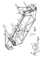
- Figure 1 shows part of a vehicle chassis or frame 2 to which two wheel supports 4 are connected by any conventional means, in this case an upper V-shaped suspension arm 6 and a similar lower suspension arm 8 which permit relative vertical movement of the chassis and wheel supports.
- Each wheel support 4 is also connected to one end of a unit comprising a coil spring 10 and damper 12 whose other end is connected to the chassis.
- torsion bar 18 Extending across the vehicle chassis and connected to it by pillow blocks 14 and 16, which permit relative rotation, is a torsion bar 18 of generally U-shape whose limbs 20 extend generally parallel to the length of the chassis, that is to say the direction of movement of the vehicle, and are connected by respective links or bars 22 to a respective wheel support 4.
- a second torsion bar which is referred to as a Z bar in that torque applied to one end of it in one sense results in a torque at the other end in the opposite sense.
- this Z bar is not in fact Z-shaped but comprises two portions, each of which is of Z-shape and extends approximately half way across the width of the chassis.
- Each portion comprises a central limb 24 which extends transverse to the length of the chassis and rotatably secured to it by the pillow blocks 14,16.
- the outer limbs 26 are connected to a respective vehicle support by the associated link 22.
- the two inner limbs 28 extend parallel to one another and are connected together at their free ends by a rigid rod 30.
- the connection of the rod 30 to the limbs 28 is by means of so-called rod ends comprising a part-spherical apertured ball 32 carried on the rod 30 and received in a corresponding aperture in the associated limb 28 whereby relative pivotal movement is permitted.
- the rod 30 is connected at its midpoint to a rigid coupling 34, constituted in this case by a simple bar, by means of a further partspherical ball 36 on the rod 30 which is received in a corresponding aperture in the upper end of the bar 34.
- the lower end of the bar 34 is connected by a simple pivotal connection 38 to the chassis 2.
- the limbs 28, rods 30 and 34 and pivotal connections 32 and 36 together constitute a torque-reversing mechanism in that if the outer limb 26 of one portion of the Z bar moves, say, upwardly, then the correspondinginner limb 28 moves downwardly and moves the associated end of the rod 30 with it. Due to the fact that the midpoint of the rod 30 is fixed in position in the vertical direction this results in the other end of the rod 30 and thus the associated limb 28 moving upwardly (as is shown in Figure 2) and thus the outer limb 26 of the other portion of the Z bar moving downwardly.
- the wheel supports 4 In use, if one of the wheel supports 4 should move vertically with respect to the chassis 2, for instance under the influence of cornering or upon impact with an obstruction, this causes a torque to be applied to the two torsion bars via the link 22 and their associated outer limbs 20 and 26.
- the U-shaped torsion bar 18,20 acts such that an input torque in one direction results in an output torque at the other end in the same direction.
- the Z bar 24,26 provides an output torque opposite to that of the input torque due to the torque-reversing mechanism described above. If the U and Z bars have equal characteristics, the output torque provided by the one bar with cancel the output torque provided by the other. The resulting output torque can, however, be adjusted to provide an output torque which varies as a function of the input torque by providing bars with different characteristics.
- the U bar 18,20 provides roll stiffness and thus counteracts the tendency of the vehicle body to roll about the vehicle roll axis 38, e.g. when cornering, but tends to lift the inside wheel from the ground as the vehicle moves in a curved path.
- the Z bar 24,26 does not contribute to roll stiffness but does provide a force which tends to keep the inside wheel in contact with the ground as the vehicle moves in a curved path.
- the U bar can be designed to provide a significant amount of roll stiffness while the torque provided by the Z bar will maintain contact between the ground and the inside wheel.
- the Z bar thus corrects for a significant defficiency in the action of the U bar and allows greater design flexibility in the roll stiffness of the U bar.
- the portions 18 and 24 of the torsion bars are accommodated wholly within the chassis or frame 2 of the vehicle.
- the outer limbs 20,26 of the torsion bars need not be acted on directly by movement of the wheel support but may be acted on indirectly via a rocker arm actuated by the wheel support by either a push rod or a pull rod. If the rocker arms are adjustable this permits the roll stiffness to be adjusted in a very simple manner.
- the roll stiffness may be further adjustable by connecting the rigid rod 30 to the inner arms 28 of the portions of the Z bar in such a manner that it may be moved fore and aft.
- the U and Z bars are appropriately dimensioned and constructed they may take over the entire spring function of the suspension system and the coil springs 10 may be omitted entirely. In this event, the adjustment of the optional rocker arms referred to above and/or of the points on the arms 28 at which the rod 30 is connected to them will result not only in an adjustment of the roll stiffness but also in adjustment of the spring rate of the entire suspension system.
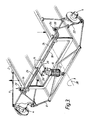
- the modified embodiment illustrated in Figure 3 is very similar to that illustrated in Figure 1 and the same reference numerals are used to designate similar components.
- the two outboard coil springs 10 and dampers 12 have been omitted and a single coil spring 10 and damper 12 have been used to replace the rigid rod 34.
- This construction operates in a very similar manner to that illustrated in Figure 1 but has the substantial advantage that the space, weight and expense of one of the two spring and damper units is saved entirely.
- the single centrally mounted spring and damper unit performs precisely the same function as the two units which were previously used and it will be appreciated that if the points of connection of the rod 30 to the arms 28 are movable the roll stiffness and suspension spring rate of the vehicle may be readily adjusted using precisely the same spring 10.
Landscapes
- Engineering & Computer Science (AREA)
- Mechanical Engineering (AREA)
- Vehicle Body Suspensions (AREA)
- Springs (AREA)
Applications Claiming Priority (2)
| Application Number | Priority Date | Filing Date | Title |
|---|---|---|---|
| US38475889A | 1989-07-25 | 1989-07-25 | |
| US384758 | 1989-07-25 |
Publications (1)
| Publication Number | Publication Date |
|---|---|
| EP0410676A1 true EP0410676A1 (fr) | 1991-01-30 |
Family
ID=23518629
Family Applications (2)
| Application Number | Title | Priority Date | Filing Date |
|---|---|---|---|
| EP90308057A Withdrawn EP0410676A1 (fr) | 1989-07-25 | 1990-07-24 | Systèmes de suspension de véhicule |
| EP90308056A Expired - Lifetime EP0410675B1 (fr) | 1989-07-25 | 1990-07-24 | Systèmes de suspension de véhicule |
Family Applications After (1)
| Application Number | Title | Priority Date | Filing Date |
|---|---|---|---|
| EP90308056A Expired - Lifetime EP0410675B1 (fr) | 1989-07-25 | 1990-07-24 | Systèmes de suspension de véhicule |
Country Status (9)
| Country | Link |
|---|---|
| EP (2) | EP0410676A1 (fr) |
| JP (1) | JPH03118206A (fr) |
| KR (1) | KR910002628A (fr) |
| AT (1) | ATE97860T1 (fr) |
| AU (1) | AU640389B2 (fr) |
| BR (1) | BR9003602A (fr) |
| CA (1) | CA2021969A1 (fr) |
| DE (1) | DE69004885D1 (fr) |
| MX (1) | MX173063B (fr) |
Cited By (8)
| Publication number | Priority date | Publication date | Assignee | Title |
|---|---|---|---|---|
| FR2726792A1 (fr) * | 1994-11-15 | 1996-05-15 | Peugeot | Dispositif anti-devers pour essieu de vehicule automobile |
| WO1997006971A1 (fr) * | 1995-08-21 | 1997-02-27 | Kinetic Limited | Amelioration des mecanismes de stabilisation en roulis pour systemes de suspension de vehicules |
| ES2128200A1 (es) * | 1995-03-30 | 1999-05-01 | Cuenda Juan Antonio Cuenda | Sistema de suspension para automovil. |
| FR2834936A1 (fr) * | 2002-01-22 | 2003-07-25 | Drom Suc | Dispositif de stabilisation de la caisse d'un vehicule routier a moteur, equipe de roues laterales supportees aux extremites d'un essieu |
| EP0952929A4 (fr) * | 1996-12-24 | 2004-07-28 | Kinetic Ltd | Systeme de suspension passif pour vehicules comprenant un mecanisme de controle du roulis |
| DE102004003149A1 (de) * | 2004-01-21 | 2005-08-11 | Volkswagen Ag | Vierlenker-Einzelradaufhängung für eine Kraftfahrzeug-Hinterachsen |
| NL2004418C2 (nl) * | 2009-12-03 | 2011-06-06 | Zuidberg Techniek Holding B V | Voorassamenstel voor een voertuig. |
| CN108688429A (zh) * | 2017-04-07 | 2018-10-23 | 郑州宇通客车股份有限公司 | 一种变刚度横向稳定装置及使用该横向稳定装置的汽车 |
Families Citing this family (8)
| Publication number | Priority date | Publication date | Assignee | Title |
|---|---|---|---|---|
| IT1246809B (it) * | 1990-05-24 | 1994-11-28 | Tonino Cervi | Dispositivo per la compensazione del rollio in autoveicoli. |
| GB2365829B (en) * | 2000-08-08 | 2004-09-22 | Oshkosh Truck Corp | Mounting assembly for a vehicle suspension arm |
| US6764085B1 (en) | 2000-08-09 | 2004-07-20 | Oshkosh Truck Corporation | Non-contact spring guide |
| KR100475907B1 (ko) * | 2001-10-19 | 2005-03-10 | 현대자동차주식회사 | 자동차용 앤티롤바의 구조 |
| KR100475910B1 (ko) | 2001-12-13 | 2005-03-10 | 현대자동차주식회사 | 상용차의 프론트 및 데드 액슬용 현가장치의 롤 저감구조 |
| EP1325822A1 (fr) * | 2002-01-02 | 2003-07-09 | Messori Engineering s.a.s di Messori P.& C. | Suspension arrière pour véhicules à moteur |
| US7559403B2 (en) | 2006-04-05 | 2009-07-14 | Schmitz Geoffrey W | Modular, central frame, offset, dual control arm independent suspension and suspension retrofit |
| CN113942356B (zh) * | 2020-07-15 | 2023-08-15 | 广州汽车集团股份有限公司 | 一种稳定杆结构及具有其的汽车 |
Citations (9)
| Publication number | Priority date | Publication date | Assignee | Title |
|---|---|---|---|---|
| US1984978A (en) * | 1932-12-22 | 1934-12-18 | Henry K Moffitt | Vehicle body equalizing mechanism |
| US2417206A (en) * | 1943-11-30 | 1947-03-11 | Larison Compensating Axle Corp | Vehicle wheel suspension |
| US2565756A (en) * | 1948-07-27 | 1951-08-28 | Coleman Howard | Combination stabilizer and torsion bar spring support |
| DE1165425B (de) * | 1962-05-19 | 1964-03-12 | Volkswagenwerk Ag | Drehstabfederung fuer Fahrzeuge, insbesondere fuer die Hinterachse eines Kraftfahrzeuges |
| US3292945A (en) * | 1964-12-10 | 1966-12-20 | Publicite Francaise | Vehicle suspensions |
| DE1231578B (de) * | 1963-04-09 | 1966-12-29 | Umberto Tremea | Ausgleichfederung fuer Strassenfahrzeuge mit an Schwinghebeln aufgehaengten Laufraedern |
| DE1236952B (de) * | 1962-10-19 | 1967-03-16 | Volkswagenwerk Ag | Ausgleichsfederung fuer Fahrzeugraeder, insbesondere der Hinterachse von Kraftfahrzeugen |
| US3315952A (en) * | 1965-05-12 | 1967-04-25 | Europ Motor Products Inc | Automotive stabilizer bar |
| DE7632574U1 (de) * | 1976-10-19 | 1978-02-09 | Boge Gmbh, 5208 Eitorf | Schwingungsdämpferanordnung für Kraftfahrzeuge |
Family Cites Families (5)
| Publication number | Priority date | Publication date | Assignee | Title |
|---|---|---|---|---|
| GB314706A (en) * | 1928-08-04 | 1929-07-04 | Georges D Espinassy De Venel | Improvements in or relating to suspension means for vehicles |
| FR1281427A (fr) * | 1960-12-01 | 1962-01-12 | Procédé et dispositif pour la suspension de véhicules terrestres | |
| FR1382104A (fr) * | 1963-06-06 | 1964-12-18 | Dispositif de suspension d'un véhicule | |
| US3290054A (en) * | 1964-07-27 | 1966-12-06 | Prieditis Paul Alexande Reinis | Vehicle suspension |
| FR2526377B1 (fr) * | 1982-05-06 | 1985-11-08 | Aerospatiale | Suspension a bras oscillants pour un train de deux roues d'un vehicule |
-
1990
- 1990-07-23 KR KR1019900011189A patent/KR910002628A/ko not_active Withdrawn
- 1990-07-23 JP JP2193203A patent/JPH03118206A/ja active Pending
- 1990-07-24 DE DE90308056T patent/DE69004885D1/de not_active Expired - Lifetime
- 1990-07-24 EP EP90308057A patent/EP0410676A1/fr not_active Withdrawn
- 1990-07-24 EP EP90308056A patent/EP0410675B1/fr not_active Expired - Lifetime
- 1990-07-24 AT AT90308056T patent/ATE97860T1/de not_active IP Right Cessation
- 1990-07-24 AU AU59717/90A patent/AU640389B2/en not_active Ceased
- 1990-07-25 CA CA002021969A patent/CA2021969A1/fr not_active Abandoned
- 1990-07-25 BR BR909003602A patent/BR9003602A/pt unknown
- 1990-07-25 MX MX021735A patent/MX173063B/es unknown
Patent Citations (9)
| Publication number | Priority date | Publication date | Assignee | Title |
|---|---|---|---|---|
| US1984978A (en) * | 1932-12-22 | 1934-12-18 | Henry K Moffitt | Vehicle body equalizing mechanism |
| US2417206A (en) * | 1943-11-30 | 1947-03-11 | Larison Compensating Axle Corp | Vehicle wheel suspension |
| US2565756A (en) * | 1948-07-27 | 1951-08-28 | Coleman Howard | Combination stabilizer and torsion bar spring support |
| DE1165425B (de) * | 1962-05-19 | 1964-03-12 | Volkswagenwerk Ag | Drehstabfederung fuer Fahrzeuge, insbesondere fuer die Hinterachse eines Kraftfahrzeuges |
| DE1236952B (de) * | 1962-10-19 | 1967-03-16 | Volkswagenwerk Ag | Ausgleichsfederung fuer Fahrzeugraeder, insbesondere der Hinterachse von Kraftfahrzeugen |
| DE1231578B (de) * | 1963-04-09 | 1966-12-29 | Umberto Tremea | Ausgleichfederung fuer Strassenfahrzeuge mit an Schwinghebeln aufgehaengten Laufraedern |
| US3292945A (en) * | 1964-12-10 | 1966-12-20 | Publicite Francaise | Vehicle suspensions |
| US3315952A (en) * | 1965-05-12 | 1967-04-25 | Europ Motor Products Inc | Automotive stabilizer bar |
| DE7632574U1 (de) * | 1976-10-19 | 1978-02-09 | Boge Gmbh, 5208 Eitorf | Schwingungsdämpferanordnung für Kraftfahrzeuge |
Non-Patent Citations (1)
| Title |
|---|
| PATENT ABSTRACTS OF JAPAN vol. 12, no. 445 (M-767)(3292) 22 November 1988, & JP-A-63 176 713 (TOYOTA) 21 July 1988 * |
Cited By (12)
| Publication number | Priority date | Publication date | Assignee | Title |
|---|---|---|---|---|
| FR2726792A1 (fr) * | 1994-11-15 | 1996-05-15 | Peugeot | Dispositif anti-devers pour essieu de vehicule automobile |
| EP0712743A1 (fr) * | 1994-11-15 | 1996-05-22 | Automobiles Peugeot | Dispositif anti-dévers pour essieu de véhicule automobile |
| ES2128200A1 (es) * | 1995-03-30 | 1999-05-01 | Cuenda Juan Antonio Cuenda | Sistema de suspension para automovil. |
| WO1997006971A1 (fr) * | 1995-08-21 | 1997-02-27 | Kinetic Limited | Amelioration des mecanismes de stabilisation en roulis pour systemes de suspension de vehicules |
| US6302417B1 (en) | 1995-08-21 | 2001-10-16 | Kinetic Limited | Roll stabilization mechanisms in vehicular suspension systems |
| EP0952929A4 (fr) * | 1996-12-24 | 2004-07-28 | Kinetic Ltd | Systeme de suspension passif pour vehicules comprenant un mecanisme de controle du roulis |
| FR2834936A1 (fr) * | 2002-01-22 | 2003-07-25 | Drom Suc | Dispositif de stabilisation de la caisse d'un vehicule routier a moteur, equipe de roues laterales supportees aux extremites d'un essieu |
| DE102004003149A1 (de) * | 2004-01-21 | 2005-08-11 | Volkswagen Ag | Vierlenker-Einzelradaufhängung für eine Kraftfahrzeug-Hinterachsen |
| DE102004003149B4 (de) * | 2004-01-21 | 2017-03-16 | Volkswagen Ag | Vierlenker-Einzelradaufhängung für eine Kraftfahrzeug-Hinterachsen |
| NL2004418C2 (nl) * | 2009-12-03 | 2011-06-06 | Zuidberg Techniek Holding B V | Voorassamenstel voor een voertuig. |
| EP2329969A1 (fr) * | 2009-12-03 | 2011-06-08 | Zuidberg Techniek Holding B.V. | Assemblage d'essieu avant pour un véhicule |
| CN108688429A (zh) * | 2017-04-07 | 2018-10-23 | 郑州宇通客车股份有限公司 | 一种变刚度横向稳定装置及使用该横向稳定装置的汽车 |
Also Published As
| Publication number | Publication date |
|---|---|
| MX173063B (es) | 1994-01-31 |
| AU640389B2 (en) | 1993-08-26 |
| EP0410675B1 (fr) | 1993-12-01 |
| JPH03118206A (ja) | 1991-05-20 |
| EP0410675A1 (fr) | 1991-01-30 |
| ATE97860T1 (de) | 1993-12-15 |
| DE69004885D1 (de) | 1994-01-13 |
| KR910002628A (ko) | 1991-02-25 |
| BR9003602A (pt) | 1991-08-27 |
| AU5971790A (en) | 1991-01-31 |
| CA2021969A1 (fr) | 1991-01-26 |
Similar Documents
| Publication | Publication Date | Title |
|---|---|---|
| US5217248A (en) | Vehicle suspension system | |
| EP0083182A2 (fr) | Suspension pour roue arrière | |
| US20020079666A1 (en) | Vehicle suspension systems | |
| US4781364A (en) | Elastic beam-torsion rod connection | |
| US3400945A (en) | Vehicle leading arm suspension system | |
| EP1789268B1 (fr) | Suspension de vehicule | |
| US20040150142A1 (en) | Steering beam axle air spring suspension | |
| US20050006868A1 (en) | Control rod suspension with outboard shock | |
| US5380036A (en) | Vehicle rear suspension system | |
| US5507516A (en) | Vehicle suspension | |
| GB2111922A (en) | Vehicle suspension system | |
| EP0015015B1 (fr) | Suspension de véhicules | |
| EP0563810B1 (fr) | Dispositif de suspension d'une paire de roues avant directrices pour un véhicule utilitaire | |
| US4616849A (en) | Trailing link beam suspension | |
| HU212319B (en) | Axle with longitudinal arms for motor vehicles and trailers | |
| US4875704A (en) | Front wheel suspension stabilizer mounting structure | |
| GB2351050A (en) | A rear suspension for a road vehicle | |
| EP1910108B1 (fr) | Suspension de roue individuelle | |
| JP3697927B2 (ja) | 車軸懸架式サスペンション | |
| EP1214209B1 (fr) | Suspensions pour vehicules | |
| GB2342902A (en) | Vehicle suspensions | |
| GB2191456A (en) | Beam axle suspension with panhard rod and torsion bar | |
| GB2309948A (en) | Limiting vehicle roll | |
| WO1990015727A1 (fr) | Systeme de suspension pour vehicules | |
| GB2351049A (en) | An independent, self-regulating passive vehicle suspension. |
Legal Events
| Date | Code | Title | Description |
|---|---|---|---|
| PUAI | Public reference made under article 153(3) epc to a published international application that has entered the european phase |
Free format text: ORIGINAL CODE: 0009012 |
|
| AK | Designated contracting states |
Kind code of ref document: A1 Designated state(s): AT BE DE ES FR GB IT NL SE |
|
| 17P | Request for examination filed |
Effective date: 19910730 |
|
| 17Q | First examination report despatched |
Effective date: 19920714 |
|
| STAA | Information on the status of an ep patent application or granted ep patent |
Free format text: STATUS: THE APPLICATION HAS BEEN WITHDRAWN |
|
| 18W | Application withdrawn |
Withdrawal date: 19930416 |