EP0410825B1 - Echangeur à plaques à circuits étanches - Google Patents
Echangeur à plaques à circuits étanches Download PDFInfo
- Publication number
- EP0410825B1 EP0410825B1 EP19900401821 EP90401821A EP0410825B1 EP 0410825 B1 EP0410825 B1 EP 0410825B1 EP 19900401821 EP19900401821 EP 19900401821 EP 90401821 A EP90401821 A EP 90401821A EP 0410825 B1 EP0410825 B1 EP 0410825B1
- Authority
- EP
- European Patent Office
- Prior art keywords
- plates
- heat exchanger
- frames
- intercalary
- holes
- Prior art date
- Legal status (The legal status is an assumption and is not a legal conclusion. Google has not performed a legal analysis and makes no representation as to the accuracy of the status listed.)
- Expired - Lifetime
Links
- 239000012530 fluid Substances 0.000 title claims description 25
- 239000002131 composite material Substances 0.000 claims 1
- 230000005855 radiation Effects 0.000 description 4
- 238000005219 brazing Methods 0.000 description 2
- 238000004519 manufacturing process Methods 0.000 description 2
- 239000000919 ceramic Substances 0.000 description 1
- 230000003750 conditioning effect Effects 0.000 description 1
- 230000001419 dependent effect Effects 0.000 description 1
- 238000002955 isolation Methods 0.000 description 1
- 239000007788 liquid Substances 0.000 description 1
- 239000000463 material Substances 0.000 description 1
- 239000002184 metal Substances 0.000 description 1
- 210000000056 organ Anatomy 0.000 description 1
- 239000007787 solid Substances 0.000 description 1
- 125000006850 spacer group Chemical group 0.000 description 1
- 229920002994 synthetic fiber Polymers 0.000 description 1
- 238000011144 upstream manufacturing Methods 0.000 description 1
Images

Classifications
-
- F—MECHANICAL ENGINEERING; LIGHTING; HEATING; WEAPONS; BLASTING
- F28—HEAT EXCHANGE IN GENERAL
- F28D—HEAT-EXCHANGE APPARATUS, NOT PROVIDED FOR IN ANOTHER SUBCLASS, IN WHICH THE HEAT-EXCHANGE MEDIA DO NOT COME INTO DIRECT CONTACT
- F28D9/00—Heat-exchange apparatus having stationary plate-like or laminated conduit assemblies for both heat-exchange media, the media being in contact with different sides of a conduit wall
- F28D9/0062—Heat-exchange apparatus having stationary plate-like or laminated conduit assemblies for both heat-exchange media, the media being in contact with different sides of a conduit wall the conduits for one heat-exchange medium being formed by spaced plates with inserted elements
- F28D9/0075—Heat-exchange apparatus having stationary plate-like or laminated conduit assemblies for both heat-exchange media, the media being in contact with different sides of a conduit wall the conduits for one heat-exchange medium being formed by spaced plates with inserted elements the plates having openings therein for circulation of the heat-exchange medium from one conduit to another
Definitions
- the present invention relates to plate heat exchangers with sealed circuits according to the preamble of claim 1.
- Such an exchanger is known from US-A-4,815,534 or FR-A-2,625,301.
- the invention relates to improvements to known exchangers, these improvements aiming to allow the circulation of fluid under pressures which can be very different, whether these fluids are liquid or gaseous.
- the invention makes it possible to manufacture exchangers for the circulation of more than two fluids, and exchangers which can, in addition, allow the conditioning of fragile components which must be kept within a narrow temperature range and which may have to be protected from the atmosphere. ambient against external factors such as radiation or radiation.
- the exchanger of the above type is characterized by the characteristics of the characterizing part of the first claim.
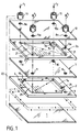
- Fig. 1 is an exploded perspective of a heat exchanger allowing a better understanding of the invention.
- Fig. 2 is a schematic elevation of a heat exchanger according to the invention.
- Fig. 3 is a perspective of particular intermediate plates intended for the exchanger of FIG. 2.
- Fig. 1 illustrates a heat exchanger in a simplified embodiment from the point of view of the circulation path of two fluids between which a heat exchange must be carried out, and allows a good understanding of the invention.
- the exchanger has a bottom plate 1 covered by a frame 2.
- the frame 2 has two holes 3, 4 aligned with two notches 5 and 6.
- the frame 2 is covered by an intermediate plate 7 in which are made holes 8, 9 and 10, 11 corresponding to the holes 3, 4, on the one hand, and to the notches 5, 6, on the other hand.
- the intermediate plate 7 is intended to be covered by a frame 2a similar to the frame 2 and having corresponding holes 3a, 4a and notches 5a, 6a but reversed with respect to the position of the holes 3, 4 and the notches 5, 6 of the frame 2.
- the frame 2a is covered by a head plate 12 having, in the illustrated embodiment, holes 8a, 9a and 10a, 11a corresponding to the holes 8, 9 and 10, 11 of the intermediate plate 7.
- the head plate 12 is provided with end pieces or fittings 13 corresponding to each of the holes 8a to 11a.
- an exchanger has a greater number of frames 2, 2a and intermediate plates 7.
- the space left free inside the frames 2, 2a is preferably used and in known manner for housing disruptors improving the heat exchange to be achieved through the intermediate plate 7.
- the assembly described above is assembled in one piece by brazing to form a unitary whole.
- the ends or fittings 13 are themselves brazed.
- bottom plates 1 and head 12 which are thicker than the intermediate plates 7, which makes it possible to relate thereto, in particular at the time of brazing, lugs or other members intended to connect the exchanger to supports.
- a first fluid follows the path illustrated by the arrows f1 and a second fluid, the path illustrated by the arrows f2.
- the two fluids are separated by the intermediate plate 7 when they are caused to circulate respectively in frame 2a and in frame 2.
- the two fluids in circulation can be fluids under high pressure since they circulate either in plate holes, or in holes or notches in frames, the width of the solid parts can be as large as desired to withstand the pressure or the difference in pressure existing between the two fluids or the difference in pressure existing between circulating fluids and atmospheric pressure.
- brazed fittings which can also be screwed if desired makes it unnecessary to use header plates.
- Fig. 2 illustrates the arrangement in which the exchanger always comprises a bottom plate 1, a head plate 12 and intermediate plates 7 stacked on one another.
- the bottom plate 1 has two holes 81, 91 and the head plate 2, two holes 101, 111.
- a first fluid circulates according to the arrows f3 and a second fluid according to the arrows f4 passing respectively through fittings 13a, 13a1 as regards the fluid in circulation according to the arrows f3 and through fittings 13b, 13b1 as regards the fluid circulating according to the arrows f4.
- each frame can be multiple passes or a single pass depending on whether or not baffles are available in the frames.
- baffles When baffles are provided, they can obviously be formed in one piece with the frames.
- the circulation of the two fluids can be carried out against the current or in the same direction or even in parallel or in series, the arrangement of the holes or notches allowing all combinations.
- Fig. 3 illustrates the invention according to which the intermediate plates 71 are constituted by two sheets 14, 15 separated by bars 16 and connected together by a heat conducting element 17 which can be constituted by a corrugated intermediate sheet.
- the intermediate plates have only one hole for each fluid flowing in one direction.
- holes can be provided for each fluid, the holes possibly also not being circular but being in the form of lights whose shape is determined so as to reduce as far as possible the pressure losses of the circulating fluid.
- the holes such as the holes 3 and 4 of a frame are provided in projecting parts 19 serving for centering the disturbers 20; a distribution channel 21 corresponding to the notches 5, 6 is thus defined upstream and downstream of each disturber.
- the entire exchanger can be contained in an isolation enclosure such as that silhouetted at 22 in FIG. 1, this enclosure can be made of synthetic material, metal, ceramic or other material suitable for the atmosphere in which the exchanger must be located as well as the organs, components or products which may have to be completely isolated from the atmosphere room to be protected from the influence of various factors such as radiation or radiation.
- the exchanger may include frames of variable thicknesses depending for some on the nature of the components which they may have to contain and which are put in place or at the same time as the disturbers 20.
- both the frames and the spacers can be provided to allow the circulation of more than two fluids. It suffices in fact to provide in each intermediate plate and each frame a greater number of holes and the notches such as 6, 6a corresponding to holes relating to each particular fluid.
Landscapes
- Engineering & Computer Science (AREA)
- Physics & Mathematics (AREA)
- Thermal Sciences (AREA)
- Mechanical Engineering (AREA)
- General Engineering & Computer Science (AREA)
- Heat-Exchange Devices With Radiators And Conduit Assemblies (AREA)
Description
- La présente invention est relative aux échangeurs à plaques à circuits étanches selon le préambule de la revendication 1. Un tel échangeur est connu par le US-A-4 815 534 ou le FR-A-2 625 301.
- L'invention concerne des perfectionnements aux échangeurs connus, ces perfectionnements visant à permettre la circulation de fluide sous des pressions pouvant être très différentes, que ces fluides soient liquides ou gazeux.
- L'invention rend possible de fabriquer des échangeurs pour la circulation de plus de deux fluides, et des échangeurs pouvant, en outre, permettre le conditionnement de composants fragiles devant être maintenus dans une fourchette de température étroite et pouvant devoir être protégés de l'atmosphère ambiante contre des facteurs extérieurs tels que des rayonnements ou radiations.
- Conformément à l'invention, l'échangeur du type ci-dessus est caractérisé par les caractéristiques de la partie caractérisante de la première revendication.
- Les revendications dépendantes présentent des modes particuliers de réalisation de l'invention.
- La présente invention sera décrite de manière plus détaillée à l'aide des dessins annexés dans lesquels :
- La fig. 1 est une perspective éclatée d'un échangeur de chaleur permettant de mieux comprendre l'invention.
- La fig. 2 est une élévation schématique d'un échangeur de chaleur conforme à l'invention.
- La fig. 3 est une perspective de plaques intercalaires particulières destinées à l'échangeur de la Fig.2.
- La fig. 1 illustre un échangeur de chaleur dans une réalisation simplifiée au point de vue du trajet de circulation de deux fluides entre lesquels un échange thermique doit être réalisé, et permet de bien comprendre l'invention.
- L'échangeur comporte une plaque de fond 1 recouverte par un cadre 2. Le cadre 2 présente deux trous 3, 4 alignés avec deux encoches 5 et 6.
- Le cadre 2 est recouvert par une plaque intercalaire 7 dans laquelle sont pratiqués des trous 8, 9 et 10, 11 correspondant aux trous 3, 4, d'une part, et aux encoches 5, 6, d'autre part. La plaque intercalaire 7 est destinée à être recouverte par un cadre 2a analogue au cadre 2 et présentant des trous 3a, 4a correspondants et des encoches 5a, 6a mais inversées par rapport à la position des trous 3, 4 et des encoches 5, 6 du cadre 2.
- Le cadre 2a est recouvert par une plaque de tête 12 présentant dans la réalisation représentée des trous 8a, 9a et 10a, 11a correspondant aux trous 8, 9 et 10, 11 de la plaque intercalaire 7. La plaque de tête 12 est munie d'embouts ou raccords 13 correspondant à chacun des trous 8a à 11a.
- Dans la pratique, un échangeur comporte un plus grand nombre de cadres 2, 2a et de plaques intercalaires 7. De même, l'espace laissé libre à l'intérieur des cadres 2, 2a est utilisé de préférence et de façon connue pour le logement de perturbateurs améliorant l'échange thermique devant être réalisé à travers la plaque intercalaire 7.
- L'ensemble décrit ci-dessus est réuni en une seule pièce par brasage pour former un tout unitaire. Les embouts ou raccords 13 sont eux-mêmes brasés.
- Il est avantageux de prévoir les plaques de fond 1 et de tête 12 plus épaisses que les plaques intercalaires 7, ce qui permet d'y rapporter, notamment au moment du brasage, des pattes ou autres organes destinés à relier l'échangeur à des supports.
- En fonctionnement dans la réalisation de la fig. 1, un premier fluide suit le trajet illustré par les flèches f₁ et un second fluide, le trajet illustré par les flèches f₂.
- On voit au dessin que les deux fluides sont séparés par la plaque intercalaire 7 lorsqu'ils sont amenés à circuler respectivement dans le cadre 2a et dans le cadre 2. Les deux fluides en circulation peuvent être des fluides sous haute pression étant donné qu'ils circulent soit dans des trous de plaques, soit dans des trous ou encoches des cadres dont la largeur des parties pleines peut être aussi importante qu'on le souhaite pour supporter la pression ou la différence de pression existant entre les deux fluides ou encore la différence de pression existant entre les fluides en circulation et la pression atmosphérique.
- L'utilisation des raccords brasés qui peuvent également être vissés si on le désire fait qu'il n'est pas nécessaire d'utiliser des plaques collectrices.
- La fig. 2 illustre la disposition dans laquelle l'échangeur comporte toujours une plaque de fond 1, une plaque de tête 12 et des plaques intercalaires 7 empilées les unes sur les autres.
- Dans cette réalisation, la plaque de fond 1 comporte deux trous 8₁, 9₁ et la plaque de tête 2, deux trous 10₁, 11₁. Un premier fluide circule suivant les flèches f₃ et un second fluide suivant les flèches f₄ en passant respectivement par des raccords 13a, 13a₁ en ce qui concerne le fluide en circulation suivant les fléches f₃ et par des raccords 13b, 13b₁ en ce qui concerne le fluide circulant suivant les flèches f₄.
- On voit par ce qui précède que la réalisation de l'échangeur à plaques et cadre permet soit de faire entrer les fluides sur un seul côté, soit de les faire entrer et sortir sur chacun des deux côtés.
- La circulation dans chaque cadre peut être à passes multiples ou à une seule passe suivant que l'on dispose ou non des chicanes dans les cadres. Lorsque des chicanes sont prévues, elles peuvent évidemment être formées d'une pièce avec les cadres.
- De même, la circulation des deux fluides peut être réalisée à contre-courant ou dans le même sens ou encore en parallèle ou en série, la disposition des trous ou encoches permettant toutes les combinaisons.
- La fig. 3 illustre l'invention selon laquelle les plaques intercalaires 7₁ sont constituées par deux feuilles 14, 15 séparées par des barrettes 16 et reliées entre elles par un élément conducteur de la chaleur 17 pouvant être constitué par une feuille intermédiaire ondulée.
- On crée ainsi entre les feuilles 14, 15 des canaux de fuite 18.
- Dans les réalisations représentées, les plaques intercalaires présentent seulement un trou pour chaque fluide circulant dans un sens.
- Il va de soi que plusieurs trous peuvent être prévus pour chaque fluide, les trous pouvant aussi ne pas être circulaires mais se présenter sous la forme de lumières dont la forme est déterminée de manière à réduire dans toute la mesure du possible les pertes de charge du fluide en circulation.
- Il est avantageux aussi, ainsi que l'illustre la fig. 1, que les trous tels que les trous 3 et 4 d'un cadre soient prévus dans des parties saillantes 19 servant au centrage des perturbateurs 20 ; on délimite ainsi en amont et en aval de chaque perturbateur un canal de répartition 21 correspondant aux encoches 5, 6.
- L'ensemble de l'échangeur peut être contenu dans une enceinte d'isolement telle que celle silhouettée en 22 à la fig. 1, cette enceinte pouvant être en matière synthétique, en métal, en céramique ou autre matière appropriée à l'atmosphère dans laquelle l'échangeur doit se trouver de même que les organes, composants ou produits qui peuvent devoir être isolés complètement de l'atmosphère ambiante pour être préservés de l'influence de facteurs divers tels que des rayonnements ou radiations.
- L'échangeur peut comporter des cadres d'épaisseurs variables dépendant pour certains de la nature des composants qu'ils peuvent devoir contenir et qui sont mis en lieu et place ou en même temps que les perturbateurs 20. De même, tant les cadres que les pièces intercalaires peuvent être prévus pour permettre la circulation de plus de deux fluides. Il suffit en effet de prévoir dans chaque plaque intercalaire et chaque cadre un plus grand nombre de trous et les encoches tels que 6, 6a correspondant à des trous relatifs à chaque fluide particulier.
Claims (9)
- Echangeur à plaques à circuits étanches, comprenant des plaques intercalaires (7) et au moins une plaque de fond (1) et/ou de tête (12) présentant des trous (8, 9, 10, 11 ; 8a, 9a, 10a, 11a) correspondant respectivement à des trous (3, 4 ; 3a, 4a) et des encoches (5, 6 ; 5a, 6a) prévus dans des cadres (2, 2a,...) disposés entre les plaques intercalaires (7) et les plaques de fond (1) et de tête (12) dont l'une au moins est munie de raccords (13), l'ensemble plaques intercalaires (7), cadres (2, 2a,...), plaques de fond (1) et de tête (12) au moins étant réuni par brasage et formant un ensemble monobloc avec les raccords (13), caractérisé en ce que le nombre de jeux de cadres (2, 2a,...), de plaques intercalaires (7), de trous (3, 4; 3a, 4a, respectivement 8-10), d'encoches (5, 6; 5a, 6a) et de raccords (13) correspond au nombre de fluides différents à faire circuler, et en ce que les plaques intercalaires (7,7₁,) comportent deux feuilles (14,15) réunies par des barrettes (16) et au moins un élément conducteur de la chaleur (17) délimitant des canaux de circulation de fuite (18).
- Echangeur suivant la revendication 1, caractérisé en ce que les plaques intercalaires (7, 7₁) sont réalisées de façon composite.
- Echangeur suivant l'une des revendications 1 ou 2, caractérisé en ce que les jeux de trous (8-10) sont percés dans les barrettes (16).
- Echangeur suivant l'une des revendications 1 à 3, caractérisé en ce que les trous (3, 4 ; 3a, 4a) des cadres (2, 2₁, ...) sont pratiqués dans des parties saillantes pour le centrage de perturbateurs (20).
- Echangeur suivant l'une des revendications 1 à 4, caractérisé en ce que les plaques de fond (1) et de tête (12) au moins sont d'épaisseurs différentes de celles des plaques intercalaires (7, 7₁).
- Echangeur suivant l'une des revendications 1 à 5, caractérisé en ce qu'on prévoit des perturbateurs (20) disposés dans les cadres (2, 2a,...) en combinaison avec les parties saillantes (19) des cadres pour délimiter des canaux de répartition (21).
- Echangeur suivant l'une des revendications 1 à 6, caractérisé en ce que l'espace délimité entre deux plaques intercalaires (7) par un cadre (2) contient des composants.
- Echangeur suivant la revendication 7, caractérisé en ce que les cadres (2, 2a, ...) sont d'épaisseur dépendant des composants devant être contenus.
- Echangeur suivant l'une des revendications 1 à 8, caractérisé en ce qu'il est disposé dans une enceinte d'isolement (22).
Applications Claiming Priority (2)
| Application Number | Priority Date | Filing Date | Title |
|---|---|---|---|
| FR8910130A FR2650382A1 (fr) | 1989-07-27 | 1989-07-27 | Echangeur a plaques a circuits etanches |
| FR8910130 | 1989-07-27 |
Publications (2)
| Publication Number | Publication Date |
|---|---|
| EP0410825A1 EP0410825A1 (fr) | 1991-01-30 |
| EP0410825B1 true EP0410825B1 (fr) | 1994-05-25 |
Family
ID=9384198
Family Applications (1)
| Application Number | Title | Priority Date | Filing Date |
|---|---|---|---|
| EP19900401821 Expired - Lifetime EP0410825B1 (fr) | 1989-07-27 | 1990-06-26 | Echangeur à plaques à circuits étanches |
Country Status (5)
| Country | Link |
|---|---|
| EP (1) | EP0410825B1 (fr) |
| DE (1) | DE69009117T2 (fr) |
| DK (1) | DK0410825T3 (fr) |
| ES (1) | ES2053138T3 (fr) |
| FR (1) | FR2650382A1 (fr) |
Families Citing this family (3)
| Publication number | Priority date | Publication date | Assignee | Title |
|---|---|---|---|---|
| FR2679021B1 (fr) * | 1991-07-12 | 1999-02-12 | Const Aero Navales | Echangeur a plaques. |
| DE102005005293A1 (de) * | 2005-02-04 | 2006-08-10 | Küba Kältetechnik GmbH | Lamellenwärmetauscher und Lamelle dafür |
| DE102010025576A1 (de) * | 2010-06-29 | 2011-12-29 | Behr Industry Gmbh & Co. Kg | Wärmetauscher |
Family Cites Families (3)
| Publication number | Priority date | Publication date | Assignee | Title |
|---|---|---|---|---|
| US3334399A (en) * | 1962-12-31 | 1967-08-08 | Stewart Warner Corp | Brazed laminated construction and method of fabrication thereof |
| US4815534A (en) * | 1987-09-21 | 1989-03-28 | Itt Standard, Itt Corporation | Plate type heat exchanger |
| FR2625301A3 (fr) * | 1987-12-23 | 1989-06-30 | Valeo Chausson Thermique | Echangeur de chaleur a plaques, notamment pour vehicule automobile, et procede de fabrication permettant d'obtenir un tel echangeur |
-
1989
- 1989-07-27 FR FR8910130A patent/FR2650382A1/fr active Pending
-
1990
- 1990-06-26 DE DE1990609117 patent/DE69009117T2/de not_active Expired - Fee Related
- 1990-06-26 DK DK90401821T patent/DK0410825T3/da active
- 1990-06-26 EP EP19900401821 patent/EP0410825B1/fr not_active Expired - Lifetime
- 1990-06-26 ES ES90401821T patent/ES2053138T3/es not_active Expired - Lifetime
Also Published As
| Publication number | Publication date |
|---|---|
| DE69009117T2 (de) | 1994-12-15 |
| DE69009117D1 (de) | 1994-06-30 |
| ES2053138T3 (es) | 1994-07-16 |
| DK0410825T3 (da) | 1994-06-20 |
| FR2650382A1 (fr) | 1991-02-01 |
| EP0410825A1 (fr) | 1991-01-30 |
Similar Documents
| Publication | Publication Date | Title |
|---|---|---|
| FR2627886A1 (fr) | Guide d'onde sonore cylindrique | |
| FR2527470A1 (fr) | Plaque filtrante | |
| FR2820555A1 (fr) | Passage de cable etanche et modulaire a positionnement de cable facilite et manchon equipe d'un tel passage | |
| CA3011196A1 (fr) | Echangeur de chaleur a condensation muni d'un dispositif d'echanges thermiques | |
| WO2009156190A1 (fr) | Chaudiere pour machine de preparation de boissons chaudes | |
| EP3922148A1 (fr) | Chaudière pour machine de préparation de boisson | |
| EP0410825B1 (fr) | Echangeur à plaques à circuits étanches | |
| EP0017082A1 (fr) | Dispositif thermoélectrique à transfert de chaleur entre un premier fluide gazeux et un deuxième fluide | |
| FR2862747A1 (fr) | Plaque d'echangeur de chaleur, et cet echangeur | |
| CH643680A5 (fr) | Electro-aimant pour frein. | |
| EP0039291A1 (fr) | Echangeur à plaques constitué par un empilement d'éléments modulaires composés de deux plaques rectangulaires identiques et d'une feuille pleine | |
| EP0860928A1 (fr) | Arbre de rotor d'une machine électrique | |
| EP0539638A1 (fr) | Echangeur de chaleur à tubes reliés par des plaques de métal déployé | |
| FR2702830A1 (fr) | Installation thermo-électrique comportant des échangeurs thermiques à plaques modulaires. | |
| FR2788118A1 (fr) | Dispositif de chauffage, ventilation et/ou climasisation comportant une boulce thermique equipee d'un evaporateur | |
| EP4121708B1 (fr) | Echangeur thermique pour véhicule automobile | |
| FR2679021A1 (fr) | Echangeur a plaques. | |
| FR2698436A1 (fr) | Echangeur massique et thermique à plaques poreuses. | |
| FR3094842A1 (fr) | Corps de régulation thermique d’un dispositif de stockage d’énergie de véhicule automobile électrique ou hybride | |
| EP1400193B1 (fr) | Capot d'appareil éléctrique du type gaufrier | |
| FR2788116A1 (fr) | Dispositif de chauffage, ventilation et/ou climatisation comportant une boucle thermique equipee d'un evaporateur | |
| EP0017083A1 (fr) | Dispositif thermoélectrique à transfert de chaleur entre deux fluides | |
| EP1364377B1 (fr) | Actionneur electromagnetique | |
| FR2747462A1 (fr) | Evaporateur a pochettes empilees resistant a la pression | |
| WO1989001599A1 (fr) | Echangeur de chaleur a impact de jet |
Legal Events
| Date | Code | Title | Description |
|---|---|---|---|
| PUAI | Public reference made under article 153(3) epc to a published international application that has entered the european phase |
Free format text: ORIGINAL CODE: 0009012 |
|
| 17P | Request for examination filed |
Effective date: 19900630 |
|
| AK | Designated contracting states |
Kind code of ref document: A1 Designated state(s): BE CH DE DK ES GB IT LI LU NL SE |
|
| 17Q | First examination report despatched |
Effective date: 19920602 |
|
| GRAA | (expected) grant |
Free format text: ORIGINAL CODE: 0009210 |
|
| AK | Designated contracting states |
Kind code of ref document: B1 Designated state(s): BE CH DE DK ES GB IT LI LU NL SE |
|
| ITF | It: translation for a ep patent filed | ||
| REG | Reference to a national code |
Ref country code: DK Ref legal event code: T3 |
|
| GBT | Gb: translation of ep patent filed (gb section 77(6)(a)/1977) |
Effective date: 19940601 |
|
| REF | Corresponds to: |
Ref document number: 69009117 Country of ref document: DE Date of ref document: 19940630 |
|
| REG | Reference to a national code |
Ref country code: ES Ref legal event code: FG2A Ref document number: 2053138 Country of ref document: ES Kind code of ref document: T3 |
|
| EPTA | Lu: last paid annual fee | ||
| EAL | Se: european patent in force in sweden |
Ref document number: 90401821.5 |
|
| PLBE | No opposition filed within time limit |
Free format text: ORIGINAL CODE: 0009261 |
|
| STAA | Information on the status of an ep patent application or granted ep patent |
Free format text: STATUS: NO OPPOSITION FILED WITHIN TIME LIMIT |
|
| 26N | No opposition filed | ||
| PGFP | Annual fee paid to national office [announced via postgrant information from national office to epo] |
Ref country code: NL Payment date: 19990628 Year of fee payment: 10 Ref country code: CH Payment date: 19990628 Year of fee payment: 10 |
|
| PGFP | Annual fee paid to national office [announced via postgrant information from national office to epo] |
Ref country code: LU Payment date: 19990702 Year of fee payment: 10 |
|
| PG25 | Lapsed in a contracting state [announced via postgrant information from national office to epo] |
Ref country code: LU Free format text: LAPSE BECAUSE OF NON-PAYMENT OF DUE FEES Effective date: 20000626 |
|
| PGFP | Annual fee paid to national office [announced via postgrant information from national office to epo] |
Ref country code: SE Payment date: 20000626 Year of fee payment: 11 |
|
| PGFP | Annual fee paid to national office [announced via postgrant information from national office to epo] |
Ref country code: DK Payment date: 20000627 Year of fee payment: 11 |
|
| PGFP | Annual fee paid to national office [announced via postgrant information from national office to epo] |
Ref country code: GB Payment date: 20000628 Year of fee payment: 11 Ref country code: ES Payment date: 20000628 Year of fee payment: 11 |
|
| PG25 | Lapsed in a contracting state [announced via postgrant information from national office to epo] |
Ref country code: LI Free format text: LAPSE BECAUSE OF NON-PAYMENT OF DUE FEES Effective date: 20000630 Ref country code: CH Free format text: LAPSE BECAUSE OF NON-PAYMENT OF DUE FEES Effective date: 20000630 |
|
| PGFP | Annual fee paid to national office [announced via postgrant information from national office to epo] |
Ref country code: DE Payment date: 20000703 Year of fee payment: 11 |
|
| PGFP | Annual fee paid to national office [announced via postgrant information from national office to epo] |
Ref country code: BE Payment date: 20000818 Year of fee payment: 11 |
|
| PG25 | Lapsed in a contracting state [announced via postgrant information from national office to epo] |
Ref country code: NL Free format text: LAPSE BECAUSE OF NON-PAYMENT OF DUE FEES Effective date: 20010101 |
|
| REG | Reference to a national code |
Ref country code: CH Ref legal event code: PL |
|
| NLV4 | Nl: lapsed or anulled due to non-payment of the annual fee |
Effective date: 20010101 |
|
| PG25 | Lapsed in a contracting state [announced via postgrant information from national office to epo] |
Ref country code: GB Free format text: LAPSE BECAUSE OF NON-PAYMENT OF DUE FEES Effective date: 20010626 Ref country code: DK Free format text: LAPSE BECAUSE OF NON-PAYMENT OF DUE FEES Effective date: 20010626 |
|
| PG25 | Lapsed in a contracting state [announced via postgrant information from national office to epo] |
Ref country code: SE Free format text: LAPSE BECAUSE OF NON-PAYMENT OF DUE FEES Effective date: 20010627 Ref country code: ES Free format text: LAPSE BECAUSE OF NON-PAYMENT OF DUE FEES Effective date: 20010627 |
|
| PG25 | Lapsed in a contracting state [announced via postgrant information from national office to epo] |
Ref country code: BE Free format text: LAPSE BECAUSE OF NON-PAYMENT OF DUE FEES Effective date: 20010630 |
|
| BERE | Be: lapsed |
Owner name: SOC. D'ETUDES ET DE CONSTRUCTIONS AERO-NAVALES Effective date: 20010630 |
|
| EUG | Se: european patent has lapsed |
Ref document number: 90401821.5 |
|
| GBPC | Gb: european patent ceased through non-payment of renewal fee |
Effective date: 20010626 |
|
| REG | Reference to a national code |
Ref country code: DK Ref legal event code: EBP |
|
| PG25 | Lapsed in a contracting state [announced via postgrant information from national office to epo] |
Ref country code: DE Free format text: LAPSE BECAUSE OF NON-PAYMENT OF DUE FEES Effective date: 20020403 |
|
| REG | Reference to a national code |
Ref country code: ES Ref legal event code: FD2A Effective date: 20030203 |
|
| PG25 | Lapsed in a contracting state [announced via postgrant information from national office to epo] |
Ref country code: IT Free format text: LAPSE BECAUSE OF NON-PAYMENT OF DUE FEES;WARNING: LAPSES OF ITALIAN PATENTS WITH EFFECTIVE DATE BEFORE 2007 MAY HAVE OCCURRED AT ANY TIME BEFORE 2007. THE CORRECT EFFECTIVE DATE MAY BE DIFFERENT FROM THE ONE RECORDED. Effective date: 20050626 |