EP0410841A1 - Verfahren und Vorrichtung zum Anbringen von Abstandhalterscheiben zwischen zwei parallelen Paneelen, insbesondere zwei Glasscheiben mit zwischenliegendem ununterbrochenem Strang - Google Patents
Verfahren und Vorrichtung zum Anbringen von Abstandhalterscheiben zwischen zwei parallelen Paneelen, insbesondere zwei Glasscheiben mit zwischenliegendem ununterbrochenem Strang Download PDFInfo
- Publication number
- EP0410841A1 EP0410841A1 EP90402005A EP90402005A EP0410841A1 EP 0410841 A1 EP0410841 A1 EP 0410841A1 EP 90402005 A EP90402005 A EP 90402005A EP 90402005 A EP90402005 A EP 90402005A EP 0410841 A1 EP0410841 A1 EP 0410841A1
- Authority
- EP
- European Patent Office
- Prior art keywords
- cord
- panels
- disc
- discs
- drawer
- Prior art date
- Legal status (The legal status is an assumption and is not a legal conclusion. Google has not performed a legal analysis and makes no representation as to the accuracy of the status listed.)
- Granted
Links
- 238000000034 method Methods 0.000 title claims description 12
- 239000011521 glass Substances 0.000 title description 27
- 230000000295 complement effect Effects 0.000 claims abstract description 8
- 239000011324 bead Substances 0.000 claims description 22
- 125000006850 spacer group Chemical group 0.000 claims description 16
- 229920005549 butyl rubber Polymers 0.000 claims description 13
- 239000004033 plastic Substances 0.000 claims description 7
- 229920003023 plastic Polymers 0.000 claims description 7
- 229920002367 Polyisobutene Polymers 0.000 claims description 5
- 239000000463 material Substances 0.000 claims description 4
- 239000000696 magnetic material Substances 0.000 claims description 3
- 230000000284 resting effect Effects 0.000 claims description 2
- 238000000605 extraction Methods 0.000 abstract 1
- 238000009434 installation Methods 0.000 description 9
- 241001639412 Verres Species 0.000 description 4
- 230000002093 peripheral effect Effects 0.000 description 4
- 238000006116 polymerization reaction Methods 0.000 description 4
- 239000007789 gas Substances 0.000 description 3
- 229910001220 stainless steel Inorganic materials 0.000 description 3
- 239000010935 stainless steel Substances 0.000 description 3
- 239000000654 additive Substances 0.000 description 2
- 230000005484 gravity Effects 0.000 description 2
- 239000002184 metal Substances 0.000 description 2
- 229910052751 metal Inorganic materials 0.000 description 2
- 235000012431 wafers Nutrition 0.000 description 2
- XLYOFNOQVPJJNP-UHFFFAOYSA-N water Chemical compound O XLYOFNOQVPJJNP-UHFFFAOYSA-N 0.000 description 2
- 229910000746 Structural steel Inorganic materials 0.000 description 1
- 230000006978 adaptation Effects 0.000 description 1
- 238000009826 distribution Methods 0.000 description 1
- 229920001971 elastomer Polymers 0.000 description 1
- 239000012530 fluid Substances 0.000 description 1
- 239000011229 interlayer Substances 0.000 description 1
- 239000007788 liquid Substances 0.000 description 1
- 238000004519 manufacturing process Methods 0.000 description 1
- 239000000203 mixture Substances 0.000 description 1
- 229920001021 polysulfide Polymers 0.000 description 1
- 229920002635 polyurethane Polymers 0.000 description 1
- 239000004814 polyurethane Substances 0.000 description 1
- 238000007789 sealing Methods 0.000 description 1
- 239000007787 solid Substances 0.000 description 1
- 238000003860 storage Methods 0.000 description 1
Images


Classifications
-
- E—FIXED CONSTRUCTIONS
- E06—DOORS, WINDOWS, SHUTTERS, OR ROLLER BLINDS IN GENERAL; LADDERS
- E06B—FIXED OR MOVABLE CLOSURES FOR OPENINGS IN BUILDINGS, VEHICLES, FENCES OR LIKE ENCLOSURES IN GENERAL, e.g. DOORS, WINDOWS, BLINDS, GATES
- E06B3/00—Window sashes, door leaves, or like elements for closing wall or like openings; Layout of fixed or moving closures, e.g. windows in wall or like openings; Features of rigidly-mounted outer frames relating to the mounting of wing frames
- E06B3/66—Units comprising two or more parallel glass or like panes permanently secured together
- E06B3/673—Assembling the units
- E06B3/67339—Working the edges of already assembled units
-
- E—FIXED CONSTRUCTIONS
- E06—DOORS, WINDOWS, SHUTTERS, OR ROLLER BLINDS IN GENERAL; LADDERS
- E06B—FIXED OR MOVABLE CLOSURES FOR OPENINGS IN BUILDINGS, VEHICLES, FENCES OR LIKE ENCLOSURES IN GENERAL, e.g. DOORS, WINDOWS, BLINDS, GATES
- E06B3/00—Window sashes, door leaves, or like elements for closing wall or like openings; Layout of fixed or moving closures, e.g. windows in wall or like openings; Features of rigidly-mounted outer frames relating to the mounting of wing frames
- E06B3/66—Units comprising two or more parallel glass or like panes permanently secured together
- E06B3/673—Assembling the units
- E06B3/67326—Assembling spacer elements with the panes
Definitions
- the present invention relates to a method and a device for placing spacing discs between two parallel flat panels, perpendicular to these panels. It more particularly relates to the use of such a method and of such a device for the installation of metal spacing discs between parallel glass sheets, joined by a continuous plastic cord, in particular of the type butyl rubber and / or polyisobutylene.
- This intermediate bead must be substantially impermeable to gases, in particular water vapor, and is for example based on butyl rubber and / or polyisobutylene, with possibly various additives, in particular dehydrating products.
- This first bead is lined with a peripheral assembly joint also made of plastic which, for its part, must be impermeable to liquid water and is for example made of polysulphide or polyurethane.
- a cord based on butyl rubber is extruded which is deposited on the periphery of a first glass plate, then applied the second sheet of glass on this cord which temporarily serves as a spacer.
- the glass sheets are then pressed to bring the height of the bead exactly to the desired height for a thickness of predetermined intermediate air space.
- the second plastic seal is then injected, the polymerization of which is caused.
- the second seal Before polymerization, the second seal must be fairly fluid, in order to seal the slightest gap between the glass and the first bead. It is therefore unable to perform its function of spacer, a function which must be temporarily held by the cord based on butyl rubber. However if it has a very high instantaneous impact resistance, it nevertheless retains a certain malleability and can therefore, as long as the peripheral seal is not polymerized, deform, for example under the weight of the glass sheets if precautions are not taken during storage and handling or if measures are not taken to accelerate the polymerization of the peripheral seal, for example the use of an oven or special compositions.
- the butyl rubber cord has, compared to the often used metallic spacer frames, the double advantage of allowing greater automation during the manufacture of the glazing and a certain flexibility of adaptation to the window frames, especially if those these tend to twist.
- the present invention aims to solve the problem of installing spacers along a plastic bead separating parallel glass plates.
- the invention also aims to propose such a method and such a device which can be used for the installation of spacers of various dimensions between glass plates of also various dimensions.
- the invention finally aims at a method and a device of this kind, the implementation of which can be managed by a programmable controller.
- the subject of the invention is a method for installing spacing discs between flat rectangular panels joined by a continuous plastic cord, in particular of the butyl rubber and / or polyisobutylene type, interposed between these panels. , in which the two panels are kept spaced from each other by said cord, spacers are applied against this cord at a distance from a rigid material arranged substantially perpendicular to the faces of the panels, parallel to a wafer at less of said panels, this method being characterized in that said discs are projected by pneumatic means towards their respective locations on said cord.
- a momentary pressure will be exerted on the disc in order to make it penetrate into the material of this bead, so that it is flush with the external surface of the bead.
- Said discs may, for example, be distributed successively and individually in a housing of a movable drawer of complementary shape having a discharge opening, this housing then being brought opposite the location of the cord intended to receive said disc, that -this being finally evacuated under pressure from its housing through said opening towards said location using pneumatic means.
- the invention also relates to a device for the installation of spacing discs between two flat rectangular panels joined by a continuous cord interposed between these panels, parallel to at least one edge of these panels, this device being characterized in that it comprises a housing with a profile complementary to said discs, provided with a discharge orifice, means for successively supplying said housing with each of said discs, means for successively bringing said housing opposite each of the locations of the cord against which said discs are to be applied and a pneumatic means controlled capable of being connected to said housing to project said disc into outside of it through said opening towards the location of the cord intended to receive it.
- this device will comprise means for maintaining said panels in an essentially vertical position, with a view to applying said disks along at least one of the parts of said cord parallel to the lower and upper edges of the panels, a cylindrical reservoir disposed vertically in which said disks are stacked, perpendicular to the upper and lower edges of said panels, a drawer movable relative to this reservoir and comprising an imprint of complementary shape of said disks, a motor means capable of moving said drawer parallel to said lower and upper wafers in order to bring said imprint first to the right of said tank to receive a disc, then to the right of the place of application of the disc on said cord, a means capable of urging the discs of the cylindrical tank towards the imprint of the drawer, and pneumatic means for ejecting the disc from said imprint, through an opening thereof, in the direction of said bead.
- the device will also include means capable of temporarily exerting pressure on the disc applied against the cord, with a view to straightening it, if it is not exactly perpendicular to the panels.
- the term “disk” means any substantially planar element of circular shape, whether it is solid or perforated, and whether or not it includes protruding parts on at least one of its faces.
- said disc will consist of a washer, which can thus be easily centered in its various positions using a centering element engaged in its central cutout.
- the means able to urge the discs of the cylindrical tank in the direction of the imprint of the drawer may comprise a simple counterweight resting on the stack of discs in the tank or an elastic return means such as a spring.
- the disc housed in the cavity will simply be held therein by gravity.
- the means capable of exerting temporary pressure on the discs applied against the cord may be constituted by a simple roller mounted idly on an axis integral with movement of the drawer.
- the entire device may include a chassis forming an application head for the spacing elements and the means capable of moving the drawer relative to this chassis may include a pneumatic or hydraulic cylinder.
- the head used for the installation of the spacing discs against the cord along the upper edge of the panels will be mounted adjustable in vertical position.
- it could, for example, be carried by a drive belt urged by a motor means and arranged vertically.
- Two heads can be used simultaneously for the installation of the spacing discs against the part of the contiguous cord, respectively, at the lower edge and at the upper edge of the panels, these being arranged vertically on a continuous conveyor which will move them with respect to the heads, in order to bring the various locations of the cord intended to receive the spacer discs in succession.
- the parallel flat panels will consist of sheets of glass, while the spacing discs of these sheets will consist of washers made of a magnetic material, but these arrangements obviously have no limiting character.
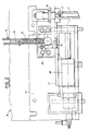
- Two devices in accordance with the invention are used as application heads, between the glass plates and against the bead 3, of metal spacers made of magnetic stainless steel . These washers are applied respectively against the part of the cord 3 contiguous to the lower edges of the plates and against the part contiguous to the upper edges.
- the lower head 7 is arranged in a fixed position at the base of a vertical column 5 carried by a frame 6.
- the upper head 8 is arranged directly above the head 7 and is adjustable in the vertical position.
- the upper head 8 is illustrated in FIGS. 2 and 3.
- It comprises a frame 13 in the form of an angle iron, which supports a reservoir tube 14, in which the spacing washers are stacked 15.
- a counterweight 16 rests on the stack of washers, to urge them down towards a distribution slide 17, slidably mounted relative to the chassis 13, under the control of a pneumatic cylinder 18.
- the drawer 17 has an imprint 19 of profile complementary to that of the washers 15. By sliding the drawer 17, this imprint 19 can be brought in line with the tube 14 and a washer 15 can thus be transferred into the imprint 19. To maintain the washer 15 in the cavity 19, this is equipped with a permanent magnet 20, which acts on the stainless steel of magnetic quality constituting the washer 15.
- the drawer 17 can then be moved to bring the imprint 19 directly above the upper part of the cord 3 to apply the washer it contains against this cord.
- the impression 19 is brought into contact by a nozzle 20 with a source of pressurized gas, for example compressed air, which makes it possible to eject the washer 15 pneumatically from the impression, through the lower opening thereof.
- pressure is then exerted on the washer using a roller 22 mounted pivoting about an axis 23, integral with the drawer 17 (FIG. 3) and arranged in such a way that the roller 22 is in contact with the cord 3. It therefore suffices to return the drawer 17 to its starting position to load a new washer 15 into the cavity 19, so that, simultaneously, the roller 21 pushes the washer 15 which comes from the butyl rubber. '' be applied against the cord 3.
- the drawer 17 is centered on the glass plates 1 and 2 and the cord 3, using a part 24 with a V section of this drawer, which covers the edge of the one of the glass plates.
- the first washer 15 to be placed on the upper part and on the lower part of the rubber bead 3 will be applied approximately 5 or 6 centimeters from the front edge of the glass plates supported by the conveyor 4. These plates will then be displaced by a length of 10 to 20 centimeters to apply a second washer, and so on, maintaining a spacing of 10 to 20 cm between the different washers, except for the last to be installed, which is applied to approximately 5 to 6 centimeters from the rear edge of the glass plates, whatever the position of the previously applied washer.
- the installation of the bead in the corners is indeed quite delicate, so it is advisable to provide in the corners of the spacers between the glass plates.
- a photocell 25 carried by the chassis 17 of the head For this purpose, the upper detects the position of the rear edge of the glass plates in order to be able to immobilize them in a position suitable for the last washer.
- the lower head 7 is quite similar to the upper head 8 and the like members are designated therein by the same reference numerals assigned with the index '. Note, however, that the imprint 18 ′ no longer has a permanent magnet, because the washer 15 ′ which is housed there and which is thrown pneumatically upwards is immobilized by gravity.
- the invention therefore provides a simple and easy to implement means for the establishment of rigid spacing washers between glass plates between which is interposed a malleable bead, in particular based on butyl rubber, without deforming the bead or induce air bubbles.
- This process optionally makes it possible to store flat volumes during the polymerization of the peripheral seal and to produce glazings whose interlayer of air can exceed, for example, 16 or 20 millimeters.
Landscapes
- Engineering & Computer Science (AREA)
- Civil Engineering (AREA)
- Structural Engineering (AREA)
- Joining Of Glass To Other Materials (AREA)
- Securing Of Glass Panes Or The Like (AREA)
- Laminated Bodies (AREA)
- Buffer Packaging (AREA)
Priority Applications (1)
| Application Number | Priority Date | Filing Date | Title |
|---|---|---|---|
| AT90402005T ATE96879T1 (de) | 1989-07-25 | 1990-07-12 | Verfahren und vorrichtung zum anbringen von abstandhalterscheiben zwischen zwei parallelen paneelen, insbesondere zwei glasscheiben mit zwischenliegendem ununterbrochenem strang. |
Applications Claiming Priority (2)
| Application Number | Priority Date | Filing Date | Title |
|---|---|---|---|
| FR8909985 | 1989-07-25 | ||
| FR8909985A FR2650331B1 (fr) | 1989-07-25 | 1989-07-25 | Procede et dispositif pour la mise en place de disques d'espacement entre deux panneaux plans paralleles, notamment entre deux feuilles de verre reunies par un cordon continu |
Publications (2)
| Publication Number | Publication Date |
|---|---|
| EP0410841A1 true EP0410841A1 (de) | 1991-01-30 |
| EP0410841B1 EP0410841B1 (de) | 1993-11-03 |
Family
ID=9384107
Family Applications (1)
| Application Number | Title | Priority Date | Filing Date |
|---|---|---|---|
| EP90402005A Expired - Lifetime EP0410841B1 (de) | 1989-07-25 | 1990-07-12 | Verfahren und Vorrichtung zum Anbringen von Abstandhalterscheiben zwischen zwei parallelen Paneelen, insbesondere zwei Glasscheiben mit zwischenliegendem ununterbrochenem Strang |
Country Status (6)
| Country | Link |
|---|---|
| EP (1) | EP0410841B1 (de) |
| AT (1) | ATE96879T1 (de) |
| DE (1) | DE69004370T2 (de) |
| DK (1) | DK0410841T3 (de) |
| ES (1) | ES2048458T3 (de) |
| FR (1) | FR2650331B1 (de) |
Families Citing this family (1)
| Publication number | Priority date | Publication date | Assignee | Title |
|---|---|---|---|---|
| DE19533855C1 (de) * | 1995-09-13 | 1997-04-24 | Lenhardt Maschinenbau | Verfahren zum Zusammenbauen von Isolierglasscheiben mit thermoplastischem Abstandhalter |
Citations (5)
| Publication number | Priority date | Publication date | Assignee | Title |
|---|---|---|---|---|
| US2111640A (en) * | 1936-04-25 | 1938-03-22 | Reinforced Paper Bottle Corp | Article forming machine |
| FR1571172A (de) * | 1968-06-27 | 1969-06-13 | ||
| GB1507305A (en) * | 1974-09-02 | 1978-04-12 | Tool Prod & Design Co Ltd | Workpiece feed mechanism |
| FR2446905A1 (fr) * | 1979-01-19 | 1980-08-14 | Ego Dichtstoffwerke | Appareil pour incorporer des corps d'espacement dans des bandes d'etancheite, notamment pour les chassis de vitres |
| EP0060202A2 (de) * | 1981-03-10 | 1982-09-15 | Saint Gobain Vitrage International | Mehrfachverglasung mit Dichtungen aus Kunststoff |
-
1989
- 1989-07-25 FR FR8909985A patent/FR2650331B1/fr not_active Expired - Fee Related
-
1990
- 1990-07-12 EP EP90402005A patent/EP0410841B1/de not_active Expired - Lifetime
- 1990-07-12 DK DK90402005.4T patent/DK0410841T3/da active
- 1990-07-12 DE DE90402005T patent/DE69004370T2/de not_active Expired - Fee Related
- 1990-07-12 ES ES90402005T patent/ES2048458T3/es not_active Expired - Lifetime
- 1990-07-12 AT AT90402005T patent/ATE96879T1/de active
Patent Citations (5)
| Publication number | Priority date | Publication date | Assignee | Title |
|---|---|---|---|---|
| US2111640A (en) * | 1936-04-25 | 1938-03-22 | Reinforced Paper Bottle Corp | Article forming machine |
| FR1571172A (de) * | 1968-06-27 | 1969-06-13 | ||
| GB1507305A (en) * | 1974-09-02 | 1978-04-12 | Tool Prod & Design Co Ltd | Workpiece feed mechanism |
| FR2446905A1 (fr) * | 1979-01-19 | 1980-08-14 | Ego Dichtstoffwerke | Appareil pour incorporer des corps d'espacement dans des bandes d'etancheite, notamment pour les chassis de vitres |
| EP0060202A2 (de) * | 1981-03-10 | 1982-09-15 | Saint Gobain Vitrage International | Mehrfachverglasung mit Dichtungen aus Kunststoff |
Also Published As
| Publication number | Publication date |
|---|---|
| EP0410841B1 (de) | 1993-11-03 |
| ES2048458T3 (es) | 1994-03-16 |
| FR2650331B1 (fr) | 1991-10-11 |
| ATE96879T1 (de) | 1993-11-15 |
| DE69004370T2 (de) | 1994-05-05 |
| DE69004370D1 (de) | 1993-12-09 |
| DK0410841T3 (da) | 1994-02-07 |
| FR2650331A1 (fr) | 1991-02-01 |
Similar Documents
| Publication | Publication Date | Title |
|---|---|---|
| EP0056762B1 (de) | Herstellung von Mehrfachverglasungen mit Gasfüllung | |
| EP1641580B1 (de) | Vorrichtung zur herstellung von dünnen pulverschichten, insbesondere bei hohen temperaturen, während eines die verwendung eines lasers auf einem material einsetzenden verfahrens | |
| EP0060202B1 (de) | Mehrfachverglasung mit Dichtungen aus Kunststoff | |
| EP0530426A1 (de) | Greif- und Übertragungszange | |
| EP0071542B1 (de) | Kontrolle des Profils von gekrümmten Platten, insbesondere der Konturen von konvexen Fensterscheiben | |
| EP0290346A1 (de) | Verfahren und Vorrichtung zum Biegen von Glasscheiben | |
| FR2928626A1 (fr) | Dispositif d'operculage etanche de contenants | |
| EP0380894B1 (de) | Vorrichtung zum Tiefziehen von Blattmaterialien | |
| FR2594410A1 (fr) | Procede de prepositionnement d'opercules sur le goulot des recipients sur lesquels ils doivent etre thermoscelles et dispositif pour sa mise en oeuvre | |
| EP0410841B1 (de) | Verfahren und Vorrichtung zum Anbringen von Abstandhalterscheiben zwischen zwei parallelen Paneelen, insbesondere zwei Glasscheiben mit zwischenliegendem ununterbrochenem Strang | |
| CA2256739A1 (fr) | Dispositif de convoyage a air pour le transport d'objets munis d'un goulot | |
| FR2725657A1 (fr) | Dispositif pour l'extrusion d'un cordon profile en polymere sur un objet en forme de plaque | |
| FR2527505A1 (fr) | Procede et installation pour le clivage de materiau, notamment de materiau schisteux | |
| EP0017564B1 (de) | Vorrichtung zur Montage von Abstandshaltern für Isolierglasscheiben | |
| FR2964897A1 (fr) | Dispositif de rectification de la hauteur de blocs beton et l'installation de production de blocs beton equipee d'un tel dispositif | |
| EP0165869B1 (de) | Vorrichtung zum Formen und Schweissen von Scheiben aus superplastischem Blechmaterial | |
| EP0626230A1 (de) | Vorrichtung zum Führen und Fördern von mindestens zwei angedockenden Blechen, und Schweissanlage mit solcher Vorrichtung | |
| EP1568424B1 (de) | Presse zum Halten und Pressen eines Werkstücks | |
| FR2606364A1 (fr) | Machine de conditionnement effectuant simultanement la fixation d'un opercule sur un contenant et sa decoupe au format | |
| FR2945470A1 (fr) | Procede et dispositif de thermoformage et de decor de recipients. | |
| FR2950030A1 (fr) | Dispositif d'operculage a tete de soudure demontable | |
| EP3820673B1 (de) | Maschine und verfahren zum laminieren von zwei flächen eines teils | |
| EP1600285A1 (de) | Vorrichtung zur Herstellung von Pastillen durch Zusammenpressen | |
| EP0124673B1 (de) | Vorrichtung zum Greifen von Paketen | |
| EP0574875B1 (de) | Tür für die einseitige Station einer Wellpappen-Herstellungsmaschine |
Legal Events
| Date | Code | Title | Description |
|---|---|---|---|
| PUAI | Public reference made under article 153(3) epc to a published international application that has entered the european phase |
Free format text: ORIGINAL CODE: 0009012 |
|
| AK | Designated contracting states |
Kind code of ref document: A1 Designated state(s): AT BE CH DE DK ES GB IT LI LU NL SE |
|
| 17P | Request for examination filed |
Effective date: 19910522 |
|
| 17Q | First examination report despatched |
Effective date: 19920212 |
|
| GRAA | (expected) grant |
Free format text: ORIGINAL CODE: 0009210 |
|
| AK | Designated contracting states |
Kind code of ref document: B1 Designated state(s): AT BE CH DE DK ES GB IT LI LU NL SE |
|
| REF | Corresponds to: |
Ref document number: 96879 Country of ref document: AT Date of ref document: 19931115 Kind code of ref document: T |
|
| REF | Corresponds to: |
Ref document number: 69004370 Country of ref document: DE Date of ref document: 19931209 |
|
| ITF | It: translation for a ep patent filed | ||
| REG | Reference to a national code |
Ref country code: DK Ref legal event code: T3 |
|
| GBT | Gb: translation of ep patent filed (gb section 77(6)(a)/1977) |
Effective date: 19940203 |
|
| REG | Reference to a national code |
Ref country code: ES Ref legal event code: FG2A Ref document number: 2048458 Country of ref document: ES Kind code of ref document: T3 |
|
| PGFP | Annual fee paid to national office [announced via postgrant information from national office to epo] |
Ref country code: SE Payment date: 19940527 Year of fee payment: 5 |
|
| PGFP | Annual fee paid to national office [announced via postgrant information from national office to epo] |
Ref country code: GB Payment date: 19940620 Year of fee payment: 5 |
|
| PGFP | Annual fee paid to national office [announced via postgrant information from national office to epo] |
Ref country code: DK Payment date: 19940630 Year of fee payment: 5 |
|
| PGFP | Annual fee paid to national office [announced via postgrant information from national office to epo] |
Ref country code: ES Payment date: 19940704 Year of fee payment: 5 |
|
| PGFP | Annual fee paid to national office [announced via postgrant information from national office to epo] |
Ref country code: AT Payment date: 19940711 Year of fee payment: 5 |
|
| PGFP | Annual fee paid to national office [announced via postgrant information from national office to epo] |
Ref country code: CH Payment date: 19940729 Year of fee payment: 5 |
|
| PGFP | Annual fee paid to national office [announced via postgrant information from national office to epo] |
Ref country code: NL Payment date: 19940731 Year of fee payment: 5 Ref country code: LU Payment date: 19940731 Year of fee payment: 5 |
|
| PGFP | Annual fee paid to national office [announced via postgrant information from national office to epo] |
Ref country code: BE Payment date: 19940804 Year of fee payment: 5 |
|
| PLBE | No opposition filed within time limit |
Free format text: ORIGINAL CODE: 0009261 |
|
| STAA | Information on the status of an ep patent application or granted ep patent |
Free format text: STATUS: NO OPPOSITION FILED WITHIN TIME LIMIT |
|
| PGFP | Annual fee paid to national office [announced via postgrant information from national office to epo] |
Ref country code: DE Payment date: 19940928 Year of fee payment: 5 |
|
| EPTA | Lu: last paid annual fee | ||
| 26N | No opposition filed | ||
| EAL | Se: european patent in force in sweden |
Ref document number: 90402005.4 |
|
| PG25 | Lapsed in a contracting state [announced via postgrant information from national office to epo] |
Ref country code: LU Free format text: LAPSE BECAUSE OF NON-PAYMENT OF DUE FEES Effective date: 19950712 Ref country code: GB Effective date: 19950712 Ref country code: DK Effective date: 19950712 Ref country code: AT Effective date: 19950712 |
|
| REG | Reference to a national code |
Ref country code: DK Ref legal event code: EBP |
|
| PG25 | Lapsed in a contracting state [announced via postgrant information from national office to epo] |
Ref country code: SE Effective date: 19950713 Ref country code: ES Free format text: LAPSE BECAUSE OF NON-PAYMENT OF DUE FEES Effective date: 19950713 |
|
| PG25 | Lapsed in a contracting state [announced via postgrant information from national office to epo] |
Ref country code: LI Effective date: 19950731 Ref country code: CH Effective date: 19950731 Ref country code: BE Effective date: 19950731 |
|
| BERE | Be: lapsed |
Owner name: SAINT-GOBAIN VITRAGE INTERNATIONAL Effective date: 19950731 |
|
| PG25 | Lapsed in a contracting state [announced via postgrant information from national office to epo] |
Ref country code: NL Effective date: 19960201 |
|
| GBPC | Gb: european patent ceased through non-payment of renewal fee |
Effective date: 19950712 |
|
| REG | Reference to a national code |
Ref country code: CH Ref legal event code: PL |
|
| NLV4 | Nl: lapsed or anulled due to non-payment of the annual fee |
Effective date: 19960201 |
|
| PG25 | Lapsed in a contracting state [announced via postgrant information from national office to epo] |
Ref country code: DE Effective date: 19960402 |
|
| EUG | Se: european patent has lapsed |
Ref document number: 90402005.4 |
|
| REG | Reference to a national code |
Ref country code: ES Ref legal event code: FD2A Effective date: 19960810 |
|
| PG25 | Lapsed in a contracting state [announced via postgrant information from national office to epo] |
Ref country code: IT Free format text: LAPSE BECAUSE OF NON-PAYMENT OF DUE FEES;WARNING: LAPSES OF ITALIAN PATENTS WITH EFFECTIVE DATE BEFORE 2007 MAY HAVE OCCURRED AT ANY TIME BEFORE 2007. THE CORRECT EFFECTIVE DATE MAY BE DIFFERENT FROM THE ONE RECORDED. Effective date: 20050712 |