EP0410873A1 - Vorrichtung zur Verbindung und Erweiterung von Bussen in einem Nachrichtenübertragungsnetz - Google Patents
Vorrichtung zur Verbindung und Erweiterung von Bussen in einem Nachrichtenübertragungsnetz Download PDFInfo
- Publication number
- EP0410873A1 EP0410873A1 EP90402130A EP90402130A EP0410873A1 EP 0410873 A1 EP0410873 A1 EP 0410873A1 EP 90402130 A EP90402130 A EP 90402130A EP 90402130 A EP90402130 A EP 90402130A EP 0410873 A1 EP0410873 A1 EP 0410873A1
- Authority
- EP
- European Patent Office
- Prior art keywords
- voltage
- bus
- buses
- voltages
- stations
- Prior art date
- Legal status (The legal status is an assumption and is not a legal conclusion. Google has not performed a legal analysis and makes no representation as to the accuracy of the status listed.)
- Granted
Links
- 230000005540 biological transmission Effects 0.000 title claims abstract description 7
- 238000010586 diagram Methods 0.000 description 5
- 230000001066 destructive effect Effects 0.000 description 1
- 238000001514 detection method Methods 0.000 description 1
Images


Classifications
-
- H—ELECTRICITY
- H04—ELECTRIC COMMUNICATION TECHNIQUE
- H04L—TRANSMISSION OF DIGITAL INFORMATION, e.g. TELEGRAPHIC COMMUNICATION
- H04L12/00—Data switching networks
- H04L12/28—Data switching networks characterised by path configuration, e.g. LAN [Local Area Networks] or WAN [Wide Area Networks]
- H04L12/40—Bus networks
- H04L12/40006—Architecture of a communication node
-
- H—ELECTRICITY
- H04—ELECTRIC COMMUNICATION TECHNIQUE
- H04L—TRANSMISSION OF DIGITAL INFORMATION, e.g. TELEGRAPHIC COMMUNICATION
- H04L12/00—Data switching networks
- H04L12/28—Data switching networks characterised by path configuration, e.g. LAN [Local Area Networks] or WAN [Wide Area Networks]
- H04L12/46—Interconnection of networks
- H04L12/4604—LAN interconnection over a backbone network, e.g. Internet, Frame Relay
- H04L12/462—LAN interconnection over a bridge based backbone
- H04L12/4625—Single bridge functionality, e.g. connection of two networks over a single bridge
Definitions
- the present invention relates to a bus interconnection device in an information transmission network by multiplexing where each bus connects a plurality of modules or stations.
- Information transmission networks comprising several stations by which information is exchanged between the stations.
- a master station can access the network at any time, while a slave station can only respond on interrogation.
- the number of stations that can be connected to the network is limited by the line interfaces providing the interface between the stations and the network.
- a line interface constitutes a load and the number of loads connectable to a bus depends on the electrical characteristics of the line interface.
- the present invention aims to provide a bus interconnection device allowing the increase in the number of stations connected while avoiding the constraints described in the previous paragraph (network manager or supervisor).
- the network behaves like a single bus to which all of the stations are connected.
- the buses are individualized and only the stations connected to the same bus are counted as a load on this bus.
- This device applies to buses with random access and non-destructive collision detection.
- the device is characterized by the fact that it includes electronic comparison means receiving the voltages of the different buses and delivering a voltage corresponding to the extreme voltage of the different input voltages and correction means applying a small deviation from said extreme voltage and means for distributing said corrected voltage to the various buses.
- the electronic comparison means are constituted by an operational voltage amplifier receiving as input the voltages of the various buses.
- the distribution means are constituted by a diode circuit receiving the corrected voltage and applying said voltage to each bus.
- Figure 1 shows a star network which includes a plurality of buses 1 to 4 carrying out the transfer of data and commands.
- the system can be extended to n buses.
- the function of routing information between the buses is provided by a connection module 5.
- the number of buses here 4 is given as an indication.
- Each bus connects a plurality of master or slave stations. These stations are identified 11 to 13 on the bus line 1, 21 to 23 on the bus line 2, 31 to 33 on the bus line 3 and 41 to 43 on the bus line 4.
- Each bus has a dominant or recessive state of tension.
- the voltages of each bus are in the range [O, Vcc].
- the dominant state corresponds to a voltage included in the interval [O, Vcc / 2 [and the recessive state corresponds to a voltage included in the interval] Vcc / 2, Vcc].
- the dominant state corresponds to a voltage included in the interval] Vcc / 2
- Vcc] and the recessive state corresponds to a voltage included in the interval [O, Vcc / 2 [.
- the 2 solutions can be used simultaneously in the case of a differential bus comprising two transmission wires.
- the dominant voltage is predominant.
- the voltage in the dominant state is in the interval [O, Vcc / 2 [.
- Each bus has a voltage denoted Vi with respect to ground. If Vmin is the lowest voltage measured on a given bus at any time, the module 5 applies to all the buses a maximum voltage equal to Vmin increased by a voltage difference ⁇ , this voltage difference being small compared to Vcc.
- the voltage in the dominant state is in the interval] Vcc / 2, Vcc].
- Each bus is at a voltage denoted Vi with respect to ground. If Vmax is the highest voltage measured on a given bus at any time, the module 5 applies to all buses a minimum voltage equal to Vmax minus a voltage difference ⁇ , this voltage difference being small compared to Vcc.
- the addition or subtraction of the voltage difference ⁇ makes it possible to avoid blockage and provides a safety margin.
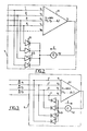
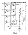
- connection module 5 illustrated in FIGS. 2 to 5 comprises an operational amplifier circuit 51 receiving the various buses and supplying a voltage to a circuit 52 which supplies via diodes 53 a voltage to the various buses 1 to 4.
- Circuit 5 includes: - Transistors 511 which compare the voltages and provide a voltage corresponding to the lower ( Figure 4) or the higher ( Figure 5) of the voltages on the different buses.
- the transistors 512 compensate for the base-emitter voltages of the various transistors 511.
- the correction means consists of a filter associated with the current generator i1 521.
- the transistors 53 mounted as voltage trackers copy the voltage supplied by the comparator 51 and adapt the impedance with respect to the buses.
Landscapes
- Engineering & Computer Science (AREA)
- Computer Networks & Wireless Communication (AREA)
- Signal Processing (AREA)
- Dc Digital Transmission (AREA)
- Small-Scale Networks (AREA)
Applications Claiming Priority (2)
| Application Number | Priority Date | Filing Date | Title |
|---|---|---|---|
| FR8909973A FR2650459B1 (fr) | 1989-07-25 | 1989-07-25 | Dispositif d'interconnexion et d'extension de bus dans un reseau de transmission d'informations |
| FR8909973 | 1989-07-25 |
Publications (2)
| Publication Number | Publication Date |
|---|---|
| EP0410873A1 true EP0410873A1 (de) | 1991-01-30 |
| EP0410873B1 EP0410873B1 (de) | 1994-03-23 |
Family
ID=9384101
Family Applications (1)
| Application Number | Title | Priority Date | Filing Date |
|---|---|---|---|
| EP90402130A Expired - Lifetime EP0410873B1 (de) | 1989-07-25 | 1990-07-25 | Vorrichtung zur Verbindung und Erweiterung von Bussen in einem Nachrichtenübertragungsnetz |
Country Status (4)
| Country | Link |
|---|---|
| US (1) | US5166957A (de) |
| EP (1) | EP0410873B1 (de) |
| DE (1) | DE69007569T2 (de) |
| FR (1) | FR2650459B1 (de) |
Cited By (1)
| Publication number | Priority date | Publication date | Assignee | Title |
|---|---|---|---|---|
| US5305465A (en) * | 1989-09-28 | 1994-04-19 | Siemens Aktiengesellschaft | Interface chip for coupling modulated signals |
Families Citing this family (6)
| Publication number | Priority date | Publication date | Assignee | Title |
|---|---|---|---|---|
| US5473264A (en) * | 1992-11-13 | 1995-12-05 | Apple Computer, Inc. | Methods and apparatus for electrically terminating a high speed communications pathway |
| US5510727A (en) * | 1994-06-27 | 1996-04-23 | Micro Linear Corporation | Optimized active SCSI termination technique |
| US5534792A (en) * | 1995-02-15 | 1996-07-09 | Burr-Brown Corporation | Low capacitance electronically controlled active bus terminator circuit and method |
| US5546017A (en) * | 1995-03-23 | 1996-08-13 | Micro Linear Corporation | Hot insertable active SCSI terminator |
| SE9701060L (sv) * | 1997-03-24 | 1998-03-04 | Asea Brown Boveri | Anläggning för överföring av elektrisk effekt |
| US6034553A (en) * | 1998-01-09 | 2000-03-07 | Pericom Semiconductor Corp. | Bus switch having both p- and n-channel transistors for constant impedance using isolation circuit for live-insertion when powered down |
Citations (2)
| Publication number | Priority date | Publication date | Assignee | Title |
|---|---|---|---|---|
| EP0081335A1 (de) * | 1981-12-03 | 1983-06-15 | Xerox Corporation | Zugriffskontrolle für Übertragungsnetzwerke |
| GB2185666A (en) * | 1986-01-16 | 1987-07-22 | Gen Electric Co Plc | A data bus coupler |
Family Cites Families (4)
| Publication number | Priority date | Publication date | Assignee | Title |
|---|---|---|---|---|
| US4498021A (en) * | 1982-07-13 | 1985-02-05 | Matsushita Electric Industrial Co., Ltd. | Booster for transmitting digital signal |
| US4670713A (en) * | 1984-07-06 | 1987-06-02 | The Babcock & Wilcox Company | Tieline control |
| US4782300A (en) * | 1986-03-03 | 1988-11-01 | International Business Machines Corporation | Differential transceiver with line integrity detection |
| SE452533B (sv) * | 1986-04-08 | 1987-11-30 | Asea Ab | Forfarande for riktningsdetektering av fel pa en kraftledning samt anordning for genomforande av det nemnda forfarandet |
-
1989
- 1989-07-25 FR FR8909973A patent/FR2650459B1/fr not_active Expired - Lifetime
-
1990
- 1990-07-25 US US07/557,656 patent/US5166957A/en not_active Expired - Lifetime
- 1990-07-25 DE DE69007569T patent/DE69007569T2/de not_active Expired - Fee Related
- 1990-07-25 EP EP90402130A patent/EP0410873B1/de not_active Expired - Lifetime
Patent Citations (2)
| Publication number | Priority date | Publication date | Assignee | Title |
|---|---|---|---|---|
| EP0081335A1 (de) * | 1981-12-03 | 1983-06-15 | Xerox Corporation | Zugriffskontrolle für Übertragungsnetzwerke |
| GB2185666A (en) * | 1986-01-16 | 1987-07-22 | Gen Electric Co Plc | A data bus coupler |
Cited By (1)
| Publication number | Priority date | Publication date | Assignee | Title |
|---|---|---|---|---|
| US5305465A (en) * | 1989-09-28 | 1994-04-19 | Siemens Aktiengesellschaft | Interface chip for coupling modulated signals |
Also Published As
| Publication number | Publication date |
|---|---|
| FR2650459A1 (fr) | 1991-02-01 |
| EP0410873B1 (de) | 1994-03-23 |
| DE69007569T2 (de) | 1994-09-08 |
| DE69007569D1 (de) | 1994-04-28 |
| FR2650459B1 (fr) | 1991-10-04 |
| US5166957A (en) | 1992-11-24 |
Similar Documents
| Publication | Publication Date | Title |
|---|---|---|
| EP0318354B1 (de) | Kraftfahrzeuginformationsübertragungsvorrichtung und Verfahren zur Anwendung der Vorrichtung | |
| EP0115717B1 (de) | Anordnung zur Übertragung von Signalen mittels Rundfunk und Kabeln zwischen einer Steuerungs- und Registrierzentrale und Datensammlungsanlagen | |
| EP1208547A1 (de) | System zur personalisierung von chipkarten | |
| EP0410873B1 (de) | Vorrichtung zur Verbindung und Erweiterung von Bussen in einem Nachrichtenübertragungsnetz | |
| EP0709254A1 (de) | Informations-Kommunikationssystem mit Stromträger, insbesonders für ein Kraftfahrzeug | |
| FR2634038A1 (fr) | Micro-ordinateur integrant une terminaison numerique d'abonne de reseau numerique a integration de services | |
| CA2361444A1 (en) | Order entry system for changing communication service | |
| FR2740264A1 (fr) | Dispositif de gestion de batteries electriques | |
| FR2750276A1 (fr) | Procede de commande de transfert d'informations entre les composants ainsi que composants pour la mise en oeuvre du procede | |
| CA1300238C (fr) | Dispositif de distribution de signaux numeriques a tres hauts debits | |
| EP0246132A1 (de) | Bidirektionaleschnittstellenschaltung mit unipolarem und bipolarem Zugang für logische Signale | |
| EP0629957A1 (de) | Bussystem mit verringerter Anzahl von Leitungen | |
| EP0547957B1 (de) | Zentralelektrik eines Fahrzeugs, insbesondere eines Kraftfahrzeugs | |
| EP0573317A1 (de) | Gerät zur Verwaltung von Zugriffspriorität zu gemeinsamen Betriebsmitteln von unter einer Vielzahl von lokalen Einheiten verteilten Funktionsmodulen, von denen jede eine lokale "Daisy-Chain"-Schaltung formt | |
| FR2513477A1 (fr) | Equipement electrique du type comprenant plusieurs cartes de circuit imprime raccordees a un plan de connexions | |
| EP0757460B1 (de) | Einrichtung zum differenziellen Übertragen von Informationen zwischen wenigstens zwei Vorrichtungen eines Fahrzeuges | |
| EP0712222A1 (de) | Anpassungsvorrichtung einer Schnittstelle eines an ein multiplexiertes Informationsübertragungsnetz angeschlossener Terminals | |
| EP0221786A2 (de) | Anzeigetafel mit Leuchtdioden | |
| FR2990311A1 (fr) | Unite de commande electronique a terminaison de ligne configurable | |
| CA2324430A1 (fr) | Dispositif et boitier pour raccordement a un reseau local | |
| FR2538140A1 (fr) | Dispositif de couplage de bus pour systeme de traitement de donnees a bus multiples | |
| FR2734106A1 (fr) | Systeme de connexion mutuelle pour des dispositifs electriques modulaires permettant de transferer des signaux optiques dans des conditions d'isolation electrique | |
| FR2641437A1 (fr) | Cartes supportant des composants electroniques et munies de cellules optiques emettrices et/ou receptrices permettant d'effectuer des echanges d'informations entre plusieurs cartes placees dans un meme appareil ou ensemble electronique et appareils ou ensembles munis de telles cartes | |
| EP4722739A1 (de) | Kombinierte aktivitäts- und intensitätskategorieanzeigevorrichtung für datenübertragungskabel | |
| FR3166716A1 (fr) | Carte électronique modulaire et système de comptage et de guidage à la place d’usagers dans un parking comprenant une telle carte |
Legal Events
| Date | Code | Title | Description |
|---|---|---|---|
| PUAI | Public reference made under article 153(3) epc to a published international application that has entered the european phase |
Free format text: ORIGINAL CODE: 0009012 |
|
| AK | Designated contracting states |
Kind code of ref document: A1 Designated state(s): DE GB IT |
|
| 17P | Request for examination filed |
Effective date: 19910710 |
|
| 17Q | First examination report despatched |
Effective date: 19930517 |
|
| GRAA | (expected) grant |
Free format text: ORIGINAL CODE: 0009210 |
|
| AK | Designated contracting states |
Kind code of ref document: B1 Designated state(s): DE GB IT |
|
| ITF | It: translation for a ep patent filed | ||
| GBT | Gb: translation of ep patent filed (gb section 77(6)(a)/1977) |
Effective date: 19940314 |
|
| REF | Corresponds to: |
Ref document number: 69007569 Country of ref document: DE Date of ref document: 19940428 |
|
| PLBE | No opposition filed within time limit |
Free format text: ORIGINAL CODE: 0009261 |
|
| STAA | Information on the status of an ep patent application or granted ep patent |
Free format text: STATUS: NO OPPOSITION FILED WITHIN TIME LIMIT |
|
| 26N | No opposition filed | ||
| PGFP | Annual fee paid to national office [announced via postgrant information from national office to epo] |
Ref country code: DE Payment date: 19950614 Year of fee payment: 6 |
|
| PGFP | Annual fee paid to national office [announced via postgrant information from national office to epo] |
Ref country code: GB Payment date: 19950615 Year of fee payment: 6 |
|
| PG25 | Lapsed in a contracting state [announced via postgrant information from national office to epo] |
Ref country code: GB Effective date: 19960725 |
|
| GBPC | Gb: european patent ceased through non-payment of renewal fee |
Effective date: 19960725 |
|
| PG25 | Lapsed in a contracting state [announced via postgrant information from national office to epo] |
Ref country code: DE Effective date: 19970402 |
|
| PGFP | Annual fee paid to national office [announced via postgrant information from national office to epo] |
Ref country code: IT Payment date: 20080717 Year of fee payment: 19 |
|
| PG25 | Lapsed in a contracting state [announced via postgrant information from national office to epo] |
Ref country code: IT Free format text: LAPSE BECAUSE OF NON-PAYMENT OF DUE FEES Effective date: 20090725 |