EP0410882B1 - Traitement d'une bande transporteuse - Google Patents
Traitement d'une bande transporteuse Download PDFInfo
- Publication number
- EP0410882B1 EP0410882B1 EP90402140A EP90402140A EP0410882B1 EP 0410882 B1 EP0410882 B1 EP 0410882B1 EP 90402140 A EP90402140 A EP 90402140A EP 90402140 A EP90402140 A EP 90402140A EP 0410882 B1 EP0410882 B1 EP 0410882B1
- Authority
- EP
- European Patent Office
- Prior art keywords
- lids
- lid
- during manufacture
- frictional
- metallic sheet
- Prior art date
- Legal status (The legal status is an assumption and is not a legal conclusion. Google has not performed a legal analysis and makes no representation as to the accuracy of the status listed.)
- Expired - Lifetime
Links
- 238000004519 manufacturing process Methods 0.000 claims abstract description 45
- 230000003416 augmentation Effects 0.000 claims abstract description 13
- 230000002093 peripheral effect Effects 0.000 claims description 8
- 238000006073 displacement reaction Methods 0.000 claims 1
- 230000009286 beneficial effect Effects 0.000 abstract 1
- 229910052751 metal Inorganic materials 0.000 description 23
- 239000002184 metal Substances 0.000 description 23
- 238000000034 method Methods 0.000 description 9
- 239000000463 material Substances 0.000 description 4
- 229920000642 polymer Polymers 0.000 description 4
- 239000002245 particle Substances 0.000 description 3
- ATJFFYVFTNAWJD-UHFFFAOYSA-N Tin Chemical compound [Sn] ATJFFYVFTNAWJD-UHFFFAOYSA-N 0.000 description 2
- 235000014214 soft drink Nutrition 0.000 description 2
- 229910052782 aluminium Inorganic materials 0.000 description 1
- XAGFODPZIPBFFR-UHFFFAOYSA-N aluminium Chemical compound [Al] XAGFODPZIPBFFR-UHFFFAOYSA-N 0.000 description 1
- 235000013405 beer Nutrition 0.000 description 1
- 230000015556 catabolic process Effects 0.000 description 1
- 238000011109 contamination Methods 0.000 description 1
- 230000003247 decreasing effect Effects 0.000 description 1
- 238000006731 degradation reaction Methods 0.000 description 1
- 238000004512 die casting Methods 0.000 description 1
- 230000000694 effects Effects 0.000 description 1
- 238000009760 electrical discharge machining Methods 0.000 description 1
- 238000012986 modification Methods 0.000 description 1
- 230000004048 modification Effects 0.000 description 1
- 238000003908 quality control method Methods 0.000 description 1
- 229910001220 stainless steel Inorganic materials 0.000 description 1
- 239000010935 stainless steel Substances 0.000 description 1
- 230000003068 static effect Effects 0.000 description 1
- 230000003746 surface roughness Effects 0.000 description 1
- 238000007514 turning Methods 0.000 description 1
- 210000003462 vein Anatomy 0.000 description 1
Images

Classifications
-
- B—PERFORMING OPERATIONS; TRANSPORTING
- B65—CONVEYING; PACKING; STORING; HANDLING THIN OR FILAMENTARY MATERIAL
- B65G—TRANSPORT OR STORAGE DEVICES, e.g. CONVEYORS FOR LOADING OR TIPPING, SHOP CONVEYOR SYSTEMS OR PNEUMATIC TUBE CONVEYORS
- B65G15/00—Conveyors having endless load-conveying surfaces, i.e. belts and like continuous members, to which tractive effort is transmitted by means other than endless driving elements of similar configuration
- B65G15/30—Belts or like endless load-carriers
- B65G15/48—Belts or like endless load-carriers metallic
-
- B—PERFORMING OPERATIONS; TRANSPORTING
- B21—MECHANICAL METAL-WORKING WITHOUT ESSENTIALLY REMOVING MATERIAL; PUNCHING METAL
- B21D—WORKING OR PROCESSING OF SHEET METAL OR METAL TUBES, RODS OR PROFILES WITHOUT ESSENTIALLY REMOVING MATERIAL; PUNCHING METAL
- B21D43/00—Feeding, positioning or storing devices combined with, or arranged in, or specially adapted for use in connection with, apparatus for working or processing sheet metal, metal tubes or metal profiles; Associations therewith of cutting devices
- B21D43/02—Advancing work in relation to the stroke of the die or tool
- B21D43/04—Advancing work in relation to the stroke of the die or tool by means in mechanical engagement with the work
- B21D43/12—Advancing work in relation to the stroke of the die or tool by means in mechanical engagement with the work by chains or belts
-
- B—PERFORMING OPERATIONS; TRANSPORTING
- B23—MACHINE TOOLS; METAL-WORKING NOT OTHERWISE PROVIDED FOR
- B23Q—DETAILS, COMPONENTS, OR ACCESSORIES FOR MACHINE TOOLS, e.g. ARRANGEMENTS FOR COPYING OR CONTROLLING; MACHINE TOOLS IN GENERAL CHARACTERISED BY THE CONSTRUCTION OF PARTICULAR DETAILS OR COMPONENTS; COMBINATIONS OR ASSOCIATIONS OF METAL-WORKING MACHINES, NOT DIRECTED TO A PARTICULAR RESULT
- B23Q7/00—Arrangements for handling work specially combined with or arranged in, or specially adapted for use in connection with, machine tools, e.g. for conveying, loading, positioning, discharging, sorting
- B23Q7/03—Arrangements for handling work specially combined with or arranged in, or specially adapted for use in connection with, machine tools, e.g. for conveying, loading, positioning, discharging, sorting by means of endless chain conveyors
-
- B—PERFORMING OPERATIONS; TRANSPORTING
- B65—CONVEYING; PACKING; STORING; HANDLING THIN OR FILAMENTARY MATERIAL
- B65G—TRANSPORT OR STORAGE DEVICES, e.g. CONVEYORS FOR LOADING OR TIPPING, SHOP CONVEYOR SYSTEMS OR PNEUMATIC TUBE CONVEYORS
- B65G2201/00—Indexing codes relating to handling devices, e.g. conveyors, characterised by the type of product or load being conveyed or handled
- B65G2201/02—Articles
Definitions
- the present invention relates to conveyor belts. More specifically, the present invention relates to an improved metal conveyor belt specifically used in the manufacture of lids for cans.
- the present invention provides a means wherein lids disposed on a conveyor belt are more firmly affixed to the belt surface. As a result, the lids are less likely to rotate during the various processes of manufacture.
- Can lids are subjected to many stresses as they are conveyed from one manufacturing station to another. As a result, the lids have a tendency to rotate within the holes in the conveyor belt in which they are placed. The rotation of the can lids prevents quality manufacture of the features on the lid. As a result, the lids must be discarded or recycled.
- the can lids are subjected to numerous forces during a specific manufacturing process. As a result, it is necessary to find a means that can hold the can lid in place during the specific manufacturing stage.
- the current process utilizes a vacuum device to hold the can lids in place during a specific stage of manufacture. Due to the usual low frictional force between the can lids and the metal surface, the vacuum that heretofore has been applied was relatively high. Moreover, the application of strong suction through a vacuum is very costly. The present invention, because it introduces additional forces between the lid and the conveyor belt, reduces the need for a strong vacuum. Therefore, the overall cost of manufacture is concordantly reduced.
- the present invention is a modification of metal conveyor belts which greatly increases the utility of metal conveyor belts in the area of tin can manufacture.
- Tin can is a generic term for cans which may be constructed of any suitable material such as aluminum.
- the present invention is defined in independent claims 1 and 10 with further embodiments disclosed in claims 2-9 and 11-16
- the surface around the hole is designed to increase the coefficient of friction between the can lid and the metal conveyor belt.
- the present invention is generally designated by 10 in Fig. 1 .
- the present invention improves upon the prior art in that it incorporates a new method for affixing can lids 11 to a metallic surface 12 .
- a groove 13 is cut into the surface of a metal plate 12 having a specific width, depth, and roughness.
- the manufacture of can lids for soft drink cans, beer cans, and the like has been plagued by one particular shortcoming.
- the can lids 11 have a tendency to rotate on the metallic surface 12 while they are being transported from one station to the next in the manufacturing process. In certain cases, this rotation is not desirable.
- the manufacture of can lids 11 for soft drinks First, the lid is printed with the appropriate messages such as "Do not litter", etc. Second, the lid 11 is engraved for the pop top. Third, the pop tab is added.
- the present machinery incorporates a vacuum device 50 to hold the lid 11 stationary.
- a groove 13 with a rough surface on the metallic plate 12 prevents the lid 11 from rotating while it is being moved from one part of the manufacturing process to another. Moreover, the vacuum that it applied can be reduced considerably, because the frictional forces between the rough surface 13 and the lid 11 increase the static rigidity of the system. In most cases, the vacuum can be decreased by a value of two. In other words, the vacuum that need be applied with the groove is half the strength of the vacuum that need be applied when the groove is not on the belt surface.
- the metal conveyor belt has been abandoned in many instances in favor of a rubber conveyor belt.
- the rubber conveyor belt is better than the metal in that the rubber surface provides a frictional surface on which the peripheral flange of the can lid 11 may sit.
- the rubber conveyor belts introduce the additional problem of high cost and require servicing that the metal conveyor belt does not.
- the metal conveyor belt avoids the particulate contamination problem associated with rubber belts.
- the metal conveyor belt is particularly smooth. It is this feature of the belt that allows the can lid 11 to rotate during manufacture.
- the present method for measuring roughness is to measure the height and depth of the peaks and valleys on a rough surface.
- the average of these values was called the root mean square or RMS.
- RMS root mean square
- a surface which has a roughness of 200 microfinish is more rough that a surface having a roughness of 100 microfinish.
- a standard metal conveyor belt has a surface roughness of 32 microfinish. As aforementioned, this is far from rough enough to prevent the can lid 11 from moving within its hole 14 in the metallic surface 12 .
- the groove 13 can be added to the metallic surface 12 in any number of possible fashions as one skilled in the art may be aware. However, in order to simplify the process, the groove 13 of the present invention is added through an electrical process known as electrical discharge machining (EDM). Of course, any suitable means to incorporate a groove 13 in the surface of a metallic surface 12 familiar to those skilled in the art may also suffice.
- EDM electrical discharge machining
- the present invention incorporates a groove 13 of 150 microfinish.
- the groove 13 is 1 thousandth of an inch (0.001) deep.
- the groove 13 is wide enough to accommodate the flanged perimeter of the lid 11 . Any greater width is not necessary as it serves no functional purpose.
- the roughness can vary between 32 to 200 microfinish and still be useful. However, if the roughness falls below an average of 100 microfinish, the metallic surface 12 becomes too smooth to hold the lid 11 in place. If the surface becomes too rough, the additional roughness serves no additional function. Moreover, the additional roughness becomes costly and requires a still deeper groove. 100 to 200 microfinish is ideal for the present application.
- the groove 13 depth also has an ideal operating range. If the groove 13 is from 1 to 3 thousandths of an inch deep, it will function ideally as required. If the groove 13 is less deep than 1 thousandth of an inch, it is not deep enough to provide a surface of the required roughness. If the groove is too deep, then the metallic surface 12 becomes weakened and will not function to specifications. Moreover, if the groove 13 is too deep, then the can lid can not effectively engage the roughened surface.
- the groove 13 of the present invention provides the answer to a twenty-five year old problem. For all of this time, manufacturers have investigated how the metallic conveyor belt could be improved to become a useful tool. The addition of the groove 13 as described provides the needed improvement to the well known system to improve its reliable functioning considerably.
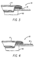
- the raised area 15 is applied to the surface and roughened to the appropriate parameters as described.
- the raised area may be composed of the same metal as the conveyor belt 12 or it may take any number of forms.
- the raised area could be composed of a polymeric material such as rubber.
- the surface would not need to be roughened.
- the polymeric compound would provide the frictional augmentation sufficient to keep the can lid 11 from rotating during manufacture.
- the roughened surface could be applied to the entire surface of the conveyor belt 12 .
- the whole belt 12 would be roughened to the appropriate roughness as previously noted.
- the entire surface of the belt 12 could be covered with a polymeric compound.
- the polymeric compound is designated as 16 throughout the applicable drawings.
Landscapes
- Engineering & Computer Science (AREA)
- Mechanical Engineering (AREA)
- Closures For Containers (AREA)
- Belt Conveyors (AREA)
- Structure Of Belt Conveyors (AREA)
Claims (16)
- Un appareil (10) pour le transport de couvercles (11) de boîtes au cours de la fabrication et de l'estampage, dans lequel chacun desdits couvercles (11) de boîtes métalliques comprend une partie centrale qui est radialement, adjacente à, monobloc avec et entourée par un rebord, ledit appareil comprenant:- une feuille métallique (12) présentant une surface supérieure et une surface inférieure,- ladite feuille métallique étant traversée d'une pluralité de trous (14) de réception de couvercle de boîte métallique,caractérisé en ce qu'il comprend en outre:- des moyens d'augmentation de friction (13; 15; 16) sur ladite feuille métallique (12), ces moyens entourant lesdits trous (14) de réception de couvercle et comprenant une zone définie, indépendamment, adjacente à chacun desdits trous de réception de couvercle de ladite feuille métallique, lesdits moyens d'augmentation de friction comprenant une zone monobloc avec ladite feuille métallique qui est elle-même gravée afin d'obtenir une rugosité spécifique sur ladite surface supérieure de la feuille,- lesdits moyens d'augmentation de friction (13; 15; 16) étant disposés par raport auxdits trous (14) de réception de couvercle afin de situer lesdits moyens d'augmentation de friction en dessous dudit rebord périphérique quand l'un desdits couvercles (11) est disposé concentriquement au-dessus de l'un desdits trous (14) de réception de couvercle de ladite feuille métallique (12),- de manière que lesdits moyens d'augmentation de friction (13; 15; 16) assurent une force de friction augmentée entre ledit rebord périphérique et ladite feuille métallique pour éviter le déplacement angulaire et radial dudit couvercle de boîte (11) par rapport à ladite feuille métallique (12).
- Un appareil pour le transport de couvercles de boîtes (11) au cours de la fabrication et de l'estampage selon la revendication 1, caractérisé en ce que:
- les plans définis respectivement, par ladite partie centrale du couvercle de boîte et par ledit rebord périphérique du couvercle de boîte sont des plans différents. - Un appareil (10) pour le transport de couvercles de boîtes (11) au cours de la fabrication et de l'estampage selon la revendication 1 ou 2, caractérisé en ce que:
- le plan défini par ladite partie centrale du couvercle de boîte est disposé dans un plan qui est en dessous dudit plan défini par ledit rebord périphérique de couvercles de boîtes. - Un appareil (10) pour le transport de couvercles de boîtes (11) au cours de la fabrication et de l'estampage selon l'une des revendications 1 à 3, caractérisé en ce que:- lesdits moyens d'augmentation de friction comprennent : une zone annulaire concentrique (13), et- ladite zone annulaire concentrique présente une largeur, une profondeur et une rugosité spécifiques,- ladite largeur spécifique n'étant pas supérieure à l'encombrement radial dudit rebord périphérique.
- Un appareil (10) pour le transport de couvercles de boîtes (11) au cours de la fabrication et de l'estampage selon l'une des revendications 1 à 4, caractérisé en ce que:
- ladite rugosité spécifique est comprise dans la gamme entre trente deux et deux cents unités sur l'échelle microfinish. - Un appareil (10) pour le transport de couvercles de boîtes (11) au cours de la fabrication et de l'estampage selon l'une des revendications 1 à 4, caractérisé en ce que:
- ladite rugosité spécifique à une valeur de cent cinquante unités sur l'échelle microfinish. - Un appareil (10) pour le transport de couvercles de boîtes (11) au cours de la fabrication et de l'estampage selon l'une des revendications 1 à 6, caractérisé en ce que:
- ladite profondeur spécifique est comprise entre un et trois millièmes de pouce (0,0254 mm à 0,0762 mm). - Un appareil (10) pour le transport de couvercles de boîtes (11) au cours de la fabrication et de l'estampage selon l'une des revendications 1 à 7, caractérisé en ce qu'il comporte en outre:
- des moyens (50), susceptibles, lors de leur actionnement, d'appliquer une force dirigée vers le bas sur lesdits couvercles de boîtes afin d'augmenter le coefficient de friction entre ledit rebord périphérique de couvercle de boîtes et lesdits moyens d'augmentation de friction. - Un appareil (10) pour le transport de couvercles de boîtes (11) au cours de la fabrication et de l'estampage selon la revendication 8, caractérisé en que:
- lesdits moyens (50) d'application de ladite force dirigée vers le bas (50) comportent une mise en dépression appliquée en dessous de ladite surface inférieure de la feuille. - Un appareil (10) pour le transport de couvercles de boîtes (11) au cours de la fabrication et de l'estampage, comprenant:- une feuille métallique (12) présentant une surface supérieure et une surface inférieure,- ladite feuille métallique étant traversée d'une pluralité de trous (14) de couvercle de boîte,caractérisé en ce qu'il comporte en outre:- des moyens d'augmentation de friction (13; 15; 16) sur ladite feuille métallique (12) entourant lesdits trous (14) de couvercle de boîte et une zone définie, indépendamment, adjacente à chacun desdits trous de couvercle de boîte de ladite feuille métallique, lesdits moyens d'augmentation de friction comprenant une zone monobloc de ladite feuille métallique gravée elle-même pour présenter une rugosité spécifique sur ladite surface supérieure de la feuille,- lesdits moyens d'augmentation de friction comportent une zone annulaire concentrique, et- ladite zone annulaire concentrique présente une largeur, une profondeur et une rugosité spécifiques.
- Un appareil (10) pour le transport de couvercles de boîtes (11) au cours de la fabrication et de l'estampage, selon la revendication 10, caractérisé en ce que:
- ladite profondeur est constituée par la distance entre la surface de ladite zone annulaire concentrique et ladite surface supérieure de la feuille. - Un appareil (10) pour le transport de couvercles de boîtes (11) au cours de la fabrication et de l'estampage, selon la revendication 10 ou 11, caractérisé en ce que:
- ladite profondeur spécifique est comprise entre un et trois millièmes de pouce (0,0254 mm à 0,0762 mm). - Un appareil (10) pour le transport de couvercles de boîtes (11) au cours de la fabrication et de l'estampage selon l'une des revendications 10 à 12, caractérisé en ce que:
- ladite rugosité spécifique est comprise dans la gamme entre trente deux et deux cents unités sur l'échelle microfinish. - Un appareil (10) pour le transport de couvercles de boîtes (11) au cours de la fabrication et de l'estampage selon l'une des revendications 10 à 13, caractérisé en ce que:
- ladite profondeur spécifique est égale à un millième de pouce (0,0254 mm). - Un appareil (10) pour le transport de couvercles de boîtes (11) au cours de la fabrication et de l'estampage selon l'une des revendications 10 à 14, caractérisé en ce que:
- ladite rugosité spécifique à une valeur de cent cinquante unités sur l'échelle microfinish. - Un appareil (10) pour le transport de couvercles de boîtes (11) au cours de la fabrication et de l'estampage selon l'une des revendications 10 à 15, caractérisé en ce que:
- ladite zone annulaire comprend une surface rugueuse usinée par décharge électrique.
Priority Applications (1)
| Application Number | Priority Date | Filing Date | Title |
|---|---|---|---|
| AT90402140T ATE94841T1 (de) | 1989-07-26 | 1990-07-25 | Ausfuehrung eines foerderbandes. |
Applications Claiming Priority (2)
| Application Number | Priority Date | Filing Date | Title |
|---|---|---|---|
| US07/385,066 US4946028A (en) | 1989-07-26 | 1989-07-26 | Conveyor belt treatment |
| US385066 | 1989-07-26 |
Publications (2)
| Publication Number | Publication Date |
|---|---|
| EP0410882A1 EP0410882A1 (fr) | 1991-01-30 |
| EP0410882B1 true EP0410882B1 (fr) | 1993-09-22 |
Family
ID=23519882
Family Applications (1)
| Application Number | Title | Priority Date | Filing Date |
|---|---|---|---|
| EP90402140A Expired - Lifetime EP0410882B1 (fr) | 1989-07-26 | 1990-07-25 | Traitement d'une bande transporteuse |
Country Status (4)
| Country | Link |
|---|---|
| US (1) | US4946028A (fr) |
| EP (1) | EP0410882B1 (fr) |
| AT (1) | ATE94841T1 (fr) |
| DE (1) | DE69003487T2 (fr) |
Families Citing this family (15)
| Publication number | Priority date | Publication date | Assignee | Title |
|---|---|---|---|---|
| US5158410A (en) * | 1990-07-26 | 1992-10-27 | Dayton Reliable Tool & Mfg. Co. | Belt and drive for conversion press |
| US5096052A (en) * | 1991-01-25 | 1992-03-17 | Raque Food Systems, Inc. | Ultrasonic sealing method and assembly |
| US5282531A (en) * | 1992-07-29 | 1994-02-01 | Crown Cork & Seal Company, Inc. | Method and apparatus for indexing can ends |
| US6070713A (en) * | 1995-04-13 | 2000-06-06 | Universal Die & Stampings, Inc. | Can end fabricating system including an improved conveyor belt drum |
| US5704754A (en) * | 1995-04-13 | 1998-01-06 | Eichmann; Harry | Can end fabricating system including an improved conveyor belt drum |
| US5668307A (en) * | 1996-05-07 | 1997-09-16 | Wade; James H. | Apparatus for testing can ends for leaks |
| JP3751452B2 (ja) * | 1998-11-13 | 2006-03-01 | 株式会社 東京ウエルズ | 電子部品搬送装置 |
| US6405853B1 (en) * | 1998-11-24 | 2002-06-18 | Steven T. Cook | Conveyor system for can end conversion systems |
| US6695132B2 (en) * | 1999-11-24 | 2004-02-24 | Dayton Systems Group, Inc. | Conveyor system for can end conversion systems |
| JP4255591B2 (ja) | 1999-12-08 | 2009-04-15 | 株式会社 東京ウエルズ | 電子部品の電極形成装置 |
| GB0717231D0 (en) * | 2007-09-05 | 2007-10-17 | Gough George T | Conveyors |
| US8695783B2 (en) * | 2009-12-14 | 2014-04-15 | Xerox Corporation | Vacuum transport belts |
| US8708135B2 (en) * | 2009-12-14 | 2014-04-29 | Xerox Corporation | Vacuum transport belts |
| US8863939B2 (en) * | 2009-12-14 | 2014-10-21 | Xerox Corporation | Surface roughness for improved vacuum pressure for efficient media hold-down performance |
| US8113338B2 (en) * | 2009-12-16 | 2012-02-14 | Suzhou Slac Precision Equipment Inc. | Wear-resistant, continuous, flexible transfer belt |
Family Cites Families (8)
| Publication number | Priority date | Publication date | Assignee | Title |
|---|---|---|---|---|
| US2698076A (en) * | 1951-04-20 | 1954-12-28 | Arenco Ab | Means for conveying containers |
| US3231065A (en) * | 1963-01-14 | 1966-01-25 | Stolle Corp | Article feeding apparatus |
| US3812953A (en) * | 1970-10-29 | 1974-05-28 | Stolle Corp | Driving or idler drum for article feeding belt |
| AU519334B2 (en) * | 1977-12-09 | 1981-11-26 | Stolle Corporation, The | Non-scuff vacuum belt conveyor |
| US4289231A (en) * | 1979-07-12 | 1981-09-15 | The Stolle Corporation | Article feeding apparatus |
| AU565192B2 (en) * | 1983-08-03 | 1987-09-10 | Broken Hill Proprietary Company Limited, The | Belt transfer mechanism |
| US4693370A (en) * | 1984-10-22 | 1987-09-15 | Rca Corporation | Pallet |
| US4799846A (en) * | 1986-11-25 | 1989-01-24 | The Minster Machine Co. | Transfer belt for can end conversion press |
-
1989
- 1989-07-26 US US07/385,066 patent/US4946028A/en not_active Expired - Lifetime
-
1990
- 1990-07-25 AT AT90402140T patent/ATE94841T1/de not_active IP Right Cessation
- 1990-07-25 EP EP90402140A patent/EP0410882B1/fr not_active Expired - Lifetime
- 1990-07-25 DE DE90402140T patent/DE69003487T2/de not_active Expired - Lifetime
Also Published As
| Publication number | Publication date |
|---|---|
| DE69003487T2 (de) | 1994-01-20 |
| ATE94841T1 (de) | 1993-10-15 |
| EP0410882A1 (fr) | 1991-01-30 |
| DE69003487D1 (de) | 1993-10-28 |
| US4946028A (en) | 1990-08-07 |
Similar Documents
| Publication | Publication Date | Title |
|---|---|---|
| EP0410882B1 (fr) | Traitement d'une bande transporteuse | |
| EP0381888B1 (fr) | Couvercle à ouverture facile pour boîte et son procédé de fabrication | |
| AU661237B1 (en) | Process for the machining of stamping parts photochemically etched out of a carrier base, and stamping webs obtained therefrom | |
| WO2002013237A2 (fr) | Procede et appareil destines a un porte-plaquettes pourvu d'une garniture | |
| CA2231469A1 (fr) | Installation de traitement de contenants, dispositif pour transporter ces contenants et palettes pour ces contenants | |
| HK94385A (en) | Integrated container manufacturing system and method | |
| CA1152020A (fr) | Dispositif d'amenee d'articles | |
| EP0764065B1 (fr) | Appareil et procede d'ejection de pieces d'usinage de machines de formage | |
| JPS58905B2 (ja) | 缶輸送装置 | |
| US6244493B1 (en) | Die bonding apparatus | |
| US4380964A (en) | Holding spindle for printing and coating cylindrical containers | |
| US7730737B2 (en) | Cooling station lifter pins | |
| US5699946A (en) | Vulcanized sheet comprising annular rubber articles, a method of and an apparatus for separating the articles from the vulcanized sheet | |
| EP0153662A1 (fr) | Dispositif rotatif de support | |
| FR2601620B1 (fr) | Procede et dispositif de fabrication et de mise en place d'une etiquette sur un recipient thermoforme. | |
| US6266992B1 (en) | Modular tooling system for lane tooling in a conversion press and method for the use thereof | |
| CN110654651A (zh) | 定位工装和电饭煲包装生产线 | |
| EP0361818A2 (fr) | Appareil de maintien de toutes sortes de plaques | |
| CA2290228A1 (fr) | Contenant pour liquide de refroidissement et methode de fabrication | |
| EP0162676A2 (fr) | Dispositif à rouleau | |
| US5282531A (en) | Method and apparatus for indexing can ends | |
| CN220233146U (zh) | 一种晶圆贴膜台的支撑部件及晶圆贴膜台 | |
| CN217889271U (zh) | 不锈钢蔬菜盘的冲压模具 | |
| US20030230547A1 (en) | Container cap | |
| JPH0732416Y2 (ja) | 紙製筒型容器 |
Legal Events
| Date | Code | Title | Description |
|---|---|---|---|
| PUAI | Public reference made under article 153(3) epc to a published international application that has entered the european phase |
Free format text: ORIGINAL CODE: 0009012 |
|
| AK | Designated contracting states |
Kind code of ref document: A1 Designated state(s): AT BE CH DE DK ES FR GB GR IT LI LU NL SE |
|
| 17P | Request for examination filed |
Effective date: 19910408 |
|
| 17Q | First examination report despatched |
Effective date: 19920629 |
|
| GRAA | (expected) grant |
Free format text: ORIGINAL CODE: 0009210 |
|
| AK | Designated contracting states |
Kind code of ref document: B1 Designated state(s): AT BE CH DE DK ES FR GB GR IT LI LU NL SE |
|
| PG25 | Lapsed in a contracting state [announced via postgrant information from national office to epo] |
Ref country code: IT Free format text: LAPSE BECAUSE OF FAILURE TO SUBMIT A TRANSLATION OF THE DESCRIPTION OR TO PAY THE FEE WITHIN THE PRE;WARNING: LAPSES OF ITALIAN PATENTS WITH EFFECTIVE DATE BEFORE 2007 MAY HAVE OCCURRED AT ANY TIME BEFORE 2007. THE CORRECT EFFECTIVE DATE MAY BE DIFFERENT FROM THE ONE RECORDED.SCRIBED TIME-LIMIT Effective date: 19930922 Ref country code: LI Effective date: 19930922 Ref country code: ES Free format text: THE PATENT HAS BEEN ANNULLED BY A DECISION OF A NATIONAL AUTHORITY Effective date: 19930922 Ref country code: CH Effective date: 19930922 Ref country code: BE Effective date: 19930922 Ref country code: SE Effective date: 19930922 Ref country code: NL Effective date: 19930922 Ref country code: DK Effective date: 19930922 Ref country code: GR Free format text: LAPSE BECAUSE OF FAILURE TO SUBMIT A TRANSLATION OF THE DESCRIPTION OR TO PAY THE FEE WITHIN THE PRESCRIBED TIME-LIMIT Effective date: 19930922 Ref country code: AT Effective date: 19930922 |
|
| REF | Corresponds to: |
Ref document number: 94841 Country of ref document: AT Date of ref document: 19931015 Kind code of ref document: T |
|
| REF | Corresponds to: |
Ref document number: 69003487 Country of ref document: DE Date of ref document: 19931028 |
|
| ET | Fr: translation filed | ||
| REG | Reference to a national code |
Ref country code: CH Ref legal event code: PL |
|
| NLV1 | Nl: lapsed or annulled due to failure to fulfill the requirements of art. 29p and 29m of the patents act | ||
| PLBE | No opposition filed within time limit |
Free format text: ORIGINAL CODE: 0009261 |
|
| STAA | Information on the status of an ep patent application or granted ep patent |
Free format text: STATUS: NO OPPOSITION FILED WITHIN TIME LIMIT |
|
| PG25 | Lapsed in a contracting state [announced via postgrant information from national office to epo] |
Ref country code: LU Free format text: LAPSE BECAUSE OF NON-PAYMENT OF DUE FEES Effective date: 19940731 |
|
| 26N | No opposition filed | ||
| REG | Reference to a national code |
Ref country code: GB Ref legal event code: IF02 |
|
| PGFP | Annual fee paid to national office [announced via postgrant information from national office to epo] |
Ref country code: FR Payment date: 20090727 Year of fee payment: 20 |
|
| PGFP | Annual fee paid to national office [announced via postgrant information from national office to epo] |
Ref country code: DE Payment date: 20090811 Year of fee payment: 20 Ref country code: GB Payment date: 20090730 Year of fee payment: 20 |
|
| REG | Reference to a national code |
Ref country code: GB Ref legal event code: PE20 Expiry date: 20100724 |
|
| PG25 | Lapsed in a contracting state [announced via postgrant information from national office to epo] |
Ref country code: GB Free format text: LAPSE BECAUSE OF EXPIRATION OF PROTECTION Effective date: 20100724 |
|
| PG25 | Lapsed in a contracting state [announced via postgrant information from national office to epo] |
Ref country code: DE Free format text: LAPSE BECAUSE OF EXPIRATION OF PROTECTION Effective date: 20100725 |